White Rose Research Online URL for this paper:
http://eprints.whiterose.ac.uk/865/
Article:
Bi, D.Q., Wang, X.H., Wang, W.J. et al. (2 more authors) (2005) Improved transient
simulation of salient-pole synchronous generators with internal and ground faults in the
stator winding. IEEE Transactions on Energy Conversion, 20 (1). pp. 128-134. ISSN
0885-8969
https://doi.org/10.1109/TEC.2004.841509
[email protected] https://eprints.whiterose.ac.uk/ Reuse
Unless indicated otherwise, fulltext items are protected by copyright with all rights reserved. The copyright exception in section 29 of the Copyright, Designs and Patents Act 1988 allows the making of a single copy solely for the purpose of non-commercial research or private study within the limits of fair dealing. The publisher or other rights-holder may allow further reproduction and re-use of this version - refer to the White Rose Research Online record for this item. Where records identify the publisher as the copyright holder, users can verify any specific terms of use on the publisher’s website.
Takedown
If you consider content in White Rose Research Online to be in breach of UK law, please notify us by
Synchronous Generators With Internal and
Ground Faults in the Stator Winding
Daqiang Bi, Xiangheng Wang, Weijian Wang, Z. Q. Zhu
, Senior Member, IEEE
, and David Howe
Abstract—An improved model for simulating the transient be-havior of salient-pole synchronous generators with internal and ground faults in the stator winding is established using the multi-loop circuit method. The model caters for faults under different ground conditions for the neutral, and accounts for the distributed capacitances of the windings to ground. Predictions from the model are validated by experiments, and it is shown that the model ac-curately predicts the voltage and current waveforms under fault conditions. Hence, it can be used to analyze important features of faults and to design appropriate protection schemes.
Index Terms—Ground fault, internal fault, multiloop circuit method, salient-pole generator.
NOMENCLATURE
Current.
Differential operator . Voltage. Flux-linkage. Mutual-inductance. Self-inductance. Resistance. Capacitance. Subscripts Three-phase windings.
Branch per phase .
Segment per branch .
Damping winding.
Damping winding loop .
Field winding. Terminal. Neutral.
Potential transformer.
I. INTRODUCTION
A
S THE capacity of single generators in power systems becomes larger, their protection becomes evermore crit-ical, since the large transient short-circuit current which may result with internal faults can cause catastrophic damage, while ground faults, which may be only slightly destructive during their initial stages, may, in the long term, develop into internalManuscript received October 23, 2003. Paper no. TEC-00152-2003. D. Bi, X. Wang, and W. Wang are with the Department of Electrical En-gineering and Applied Electronic Technology, Tsinghua University, Beijing 100084, China (e-mail: [email protected]).
Z. Q. Zhu and D. Howe are with the Department of Electronic and Electrical Engineering, University of Sheffield, Sheffield S1 3JD, U.K.
Digital Object Identifier 10.1109/TEC.2004.841509
short-circuit faults. Therefore, appropriate protection schemes must be employed to cater for both internal and ground faults. Hence, a comprehensive simulation model is required to ana-lyze the characteristics of such faults and to accurately predict the associated voltage and current waveforms.
Several methods for analyzing the effect of internal faults in synchronous generators have been proposed [1]–[7]. Strong space harmonics exist in the air-gap magnetic field and signif-icant time harmonics exist in the phase currents due to the re-sulting asymmetry in the stator windings. Hence, the symmet-rical component method which was employed in [1], [2] can lead to significant errors. Direct phase quantities were used in [3], [4] to study the effect of internal faults, including internal faults between turns and the neutral of the stator winding. It was assumed that the winding inductances relative to the air-gap field were proportional to the product of the effective numbers of turns of the corresponding windings. However, this is cor-rect only when the air-gap field has a fundamental component or if the windings are concentrated. A direct phase representa-tion was also used in [5]–[7], and a unique winding partirepresenta-tion technique was employed to analyze internal faults. A winding with an internal fault was divided into two sub-windings, each being treated as an equivalent sinusoidally distributed winding. However, space harmonics in the air-gap field were neglected and no experimental validation was provided.
To date, the analysis of ground faults has focused mainly on the characteristics of the zero-sequence fundamental and third-harmonic voltage components by using equivalent cir-cuits. However, since the distribution of the third-harmonic voltage of each coil in different branches of the stator winding may be different, the equivalent circuits for turbo-generators presented in [8]–[10] cannot be applied to salient-pole gen-erators. For a salient-pole generator with multiple branches, the analysis of the third-harmonic voltage generally adopts the superposition principle based on the potential of each turn [11], the fundamental and third-harmonic components being calculated independently. However, this is not always valid in practice and, hence, the utility of the simulation model is limited.
Although several machine models are employed in commer-cial software for the analysis of power systems, such as EMTP [12] and EMTDC [13], the generators are generally considered as healthy units, and the software is not capable of analyzing the effect of internal and ground faults.
The basic principle of the multiloop circuit method devel-oped in [14] and [15] is to generate equations for the voltages and flux-linkages according to the actual circuit loops of the
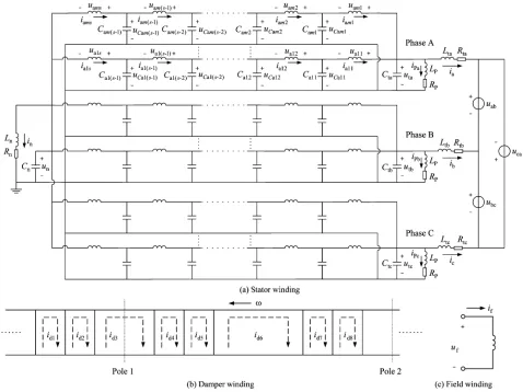
Fig. 1. Simulation model for fault on stator winding of salient-pole generator.
machine, using appropriate circuit parameters. The method has been verified by experiments, and shown to be capable of ana-lyzing the steady-state and transient behavior of internal faults in the stator windings of synchronous generators [16], [17] since it accounts for the actual disposition of the windings and accu-rately calculates the harmonics in the air-gap field. However, since the distributed capacitances of the windings to ground are neglected, while the grounding method for the neutral is not considered, ground faults could not be simulated and analyzed. Therefore, the aim of this paper is to extend the multi-loop cir-cuit method to cater for both internal and ground faults under different neutral ground conditions and to account for the dis-tributed capacitances of the windings to ground.
II. ANALYTICAL MODEL BASED ON MULTILOOPCIRCUITMETHOD
A. Definition of Reference Direction
For the stator winding shown in Fig. 1(a), the generator rule is adopted and positive current produces a negative flux-linkage. For the rotor windings, i.e., both the field winding and the damper winding shown in Fig. 1(b) and (c), the motor rule is adopted and positive current produces a positive flux-linkage. Positive voltage drops and current polarities in the stator and
rotor windings, as well as positive voltage drops across the ca-pacitances, the neutral grounding resistance and inductance , and the voltage transformer parameters and at the generator terminals, are also indicated in Fig. 1.
B. Division of Distributed Capacitance
Each stator phase winding is composed of branches in par-allel, and each branch consists of coils in series. Assuming that , , and , the capacitances of phases , and to ground, respectively, are evenly distributed in the winding, then the ca-pacitance of each coil of phases , and is , and , respectively. In the model, every branch is divided into segments from the ter-minal to the neutral, and the th segment includes coils (where ). The distributed capacitance of each seg-ment of the winding is replaced by two equal lumped capaci-tances at both ends. At the terminals, the additional capacicapaci-tances of phases , , and ,viz.the equivalent capacitances between the terminals and the low-voltage winding of the step-up trans-former are , , and , respectively. Thus, in the stator model, the equivalent capacitances can be expressed as follows:
at the terminals ,
, and ; inside the stator winding
, , and
, ( , ); at
C. Establishment of State Equations
The currents through the inductances and the voltages across the capacitances are chosen as the state variables, and the state equations are established for both healthy and fault states.
In the following, the equivalent resistances and inductances of phases , , and from the terminals to the infinite bus, in-cluding the step-up transformer and the transmission line, are , , , and , , , respectively. The calculation of the winding inductances has been described in detail in [15] and [16]. It is worth mentioning that for a salient-pole gener-ator, the self- and mutual-inductance between segments of the stator winding, and the mutual-inductance between the stator and rotor windings are dependent on the angular position of the rotor; while the self- and mutual-inductances of the rotor wind-ings are independent of the angular position of the rotor.
1) Healthy State:
a) Voltage Equations of Independent Loops: The voltage equations for each segment of the stator winding can be ex-pressed as shown in (1), at the bottom of the page, where the state variable vector is
and the inductance row vector of segment of branch of phase is
The inductance vectors of the winding segments of phases and are similar.
The voltage equations for internal loops of the stator winding are as shown in (2), at the bottom of the page, where
(3)
where is the resistance of damper loop , is the number of damper loops, and is the resistance of one
damper bar ( , ).
The inductance row vector of loop of the damper winding is
The inductance vectors of other damper winding loops are similar. The voltage equation of the field winding loop is
(4)
where is the resistance of the field winding. The inductance vector of the field winding is
At the terminals, the voltage equations for the load loops are
(5) where and are the line voltages of the infinite bus.
For the loops of the voltage transformer, the voltage equations are
(6)
where and are the magnetizing inductance and resis-tance, respectively, of the voltage transformer at the generator terminals.
For the neutral loop, the voltage equation is
(7)
b) Node Current Equations: At the internal nodes of the stator, the current equations are shown in (8), at the bottom of the next page.
(1)
and
At the terminals, the current equations are
(9)
At the neutral, the current equation is
(10)
c) State Equations: Combining the foregoing voltage equations of the independent loops (1)–(7) and the node current (8)–(10), the state equations in matrix form are as follows:
(11)
where
inductance matrix of the stator and rotor windings;
capacitance matrix of the stator winding; capacitance matrix from the terminals to the neutral;
resistance matrix of the stator and rotor windings;
, , , associated connection matrices between the nodes and branches;
zero matrix;
voltage source vector; , , , vector of state variables;
fault-conductance matrix between the fault node and branch. Under normal conditions, . However, when a fault occurs, some zero elements need to be modified ac-cording to the fault location, as will be dis-cussed.
The total order of the coefficient matrix is . 2) Ground Faults: Only one resistance branch is appended when a ground fault occurs at a node in the stator winding model via a transition resistance . Therefore, the topology of the complete circuit and the number of state variables remains the same. In other words, only the current equation at the fault
[image:5.594.41.292.273.636.2]Fig. 2. Ground fault at nodejin phasea.
Fig. 3. Inter-turn fault between nodesj andj in branchkof phasea.
node, rather than the voltage equation, needs to be modified. As-suming a ground fault occurs at segment (node ) of branch of phase , by way of example, Fig. 2, the current equation with the ground fault is changed to the following:
(12)
Thus, in matrix , a zero element on the leading diagonal needs to be substituted by according to the fault location.
3) Internal Faults: When an inter-turn fault occurs in the same branch, or a fault occurs between different branches in the same phase or between different phases, it may be represented by a transition resistance between different nodes, the circuit topology remaining the same as that for a ground fault. The state equation can be obtained by updating the current equation according to the fault location. The modification is illustrated by (13) for an inter-turn fault between node and node in branch of phase , Fig. 3
(13) In matrix , replaces two zero elements on the leading diagonal at the appropriate fault positions, and replaces two zero elements at the related off-diagonal fault positions.
In summary, a ground fault and an internal fault can be uni-fied in the model by updating the fault- conductance matrix according to the type and position of the fault.
III. SOLVINGSTATEEQUATIONS
The semi-implicit Calahan method [18] is chosen to solve the state equations. Iteration is not needed in the calculation due to the explicit recursive relation. Moreover, its computing speed and stability are better than for the fourth-order Runga–Kutta method.
the recursive relation in the Calahan method is given by
where
is a unit matrix, is the calculation time step,
, [18].
By adopting a nonzero transition resistance, albeit very small, to simulate either a solid ground fault or an internal short-circuit fault, the Calahan method ensures good stability toward a solu-tion.
IV. SIMULATION ANDEXPERIMENTALRESULTS
Extensive experiments, encompassing inter-turn faults in the same branch, faults between different branches in the same phase or between different phases, and ground faults, have been carried out on a salient-pole synchronous generator on no-load, with different excitation currents, and under different neutral grounding conditions. Some typical predicted and measured results will be reported in this section to demonstrate the generality and accuracy of the developed model. The main data for the experimental generator are: rated volt-amps ; rated power ; rated voltage ; rated current ; excitation current on no-load and rated voltage ; number of pole-pairs ; number of parallel branches per phase ; number of coils per branch of stator phase winding ; number of damper bars per pole ; capacitances of stator phases , and to ground , 1.96 and 2.11 nF, respectively. A tap from each coil of the stator winding exists in the experimental generator so as to enable the type of fault and its location to be selected. In the investigation, each branch is divided into seven segments from the terminal to the neutral.
A. Internal Fault
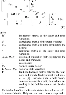
[image:6.594.321.537.66.422.2] [image:6.594.46.257.137.341.2]The excitation current was reduced to 2.85 A in order to avoid an excessively high fault current, while the neutral was grounded via a potential transformer. The measured and simu-lated short-circuit current and excitation current are com-pared in Fig. 4(a) and (b) when an inter-turn short-circuit fault
Fig. 4. Current waveforms with inter-turn fault.
is imposed across coil 7 of branch 2 in the phase winding, which is adjacent to the neutral point, when the transition resis-tance is 0.95 . In general, it can be seen that the simulation results agree well with the experimental results.
Fig. 4 shows that the short-circuit current which results with an internal fault is very large, being nearly four times the rated current even with the reduced excitation current. Further, har-monic analysis shows that the distortion of the current wave-forms is significant, the excitation current containing a strong second harmonic in addition to the direct current component, while the stator current contains a pronounced third harmonic.
B. Ground Fault
The ground faults were applied with an excitation current of 7.7 A. Thus, the voltage between the terminals and ground was approximately equal to the rated phase voltage.
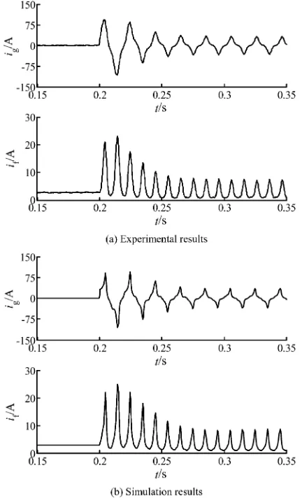
To verify the method of distributing the capacitance in the mathematical model, voltage waveforms were measured when a direct ground fault was applied on coil 2 of branch 1 in the phase winding, while the neutral was ungrounded and there was no additional capacitance or voltage transformer at the terminals. The measured and simulated zero sequence voltages at the
ter-minals and the neutral ( and , )
Fig. 5. Zero-sequence voltages with solid ground fault (ungrounded neutral).
components ( and ) of and have also been cal-culated in real time by Fourier transform using a moving data window. Again, excellent agreement is achieved.
It is observed that before the ground fault occurs, the values of and are similar, while and are very small since the stator winding is symmetrical and the capacitances of the three phases , and to ground are very similar,viz.2.01 nF, 1.96 nF, and 2.11 nF, as mentioned earlier. After the fault,
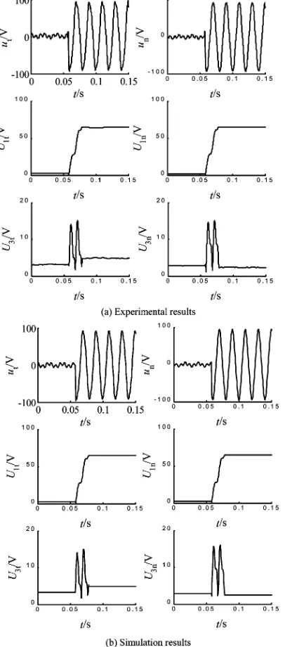
becomes higher than , while the changes in and are similar, which indicates that the zero-sequence fundamental frequency voltage can be extracted either at the generator termi-nals or at the neutral if it is to be used in the protection scheme. In practice, the capacitance of each phase to ground is not as symmetrical as in the foregoing. To simulate the asymmet-rical situation, three capacitances of 136.6, 107.8, and 106.4 nF are connected in parallel across the terminals of phases , , and , respectively, and the neutral is grounded via a resistor
Fig. 6. Zero-sequence voltages with ground fault via a resistance of 8.281k (the neutral is grounded via a resistance of 3.554k).
[image:7.594.65.268.69.529.2]V. CONCLUSIONS
Based on the multiloop circuit method, a comprehensive tran-sient model has been established for predicting the current and voltage waveforms which results in a salient-pole synchronous generator when internal faults or ground faults occur on the stator winding. Good agreement has been achieved between simulated and measured results for both types of fault, and some important characteristics of the faults have been revealed. Thus, the model can be used to analyze the effects of various fault con-ditions on the stator windings, and to aid the design of protection schemes.
REFERENCES
[1] V. A. Kinitsky, “Calculation of internal fault currents in synchronous machines,”IEEE Trans. Pattern Appl. Syst., vol. PAS-84, no. 5, pp. 391–389, May 1965.
[2] , “Digital computer calculation of internal fault currents in a syn-chronous machine,”IEEE Trans. Pattern Appl. Syst., vol. 87, no. PAS-8, pp. 1675–1679, Aug. 1968.
[3] A. I. Megahed and O. P. Malik, “Synchronous generator internal fault computation experimental verification,”Proc. Inst. Elect. Eng., Gen. Transm. Distrib., vol. 145, no. 5, Sep. 1998.
[4] , “Simulation of internal faults in synchronous generators,”IEEE Trans. Energy Convers,, vol. 14, no. 4, pp. 1306–1311, Dec. 1999. [5] P. P. Reichmeider, D. Querrey, C. A. Gross, D. Novosel, and S. Salon,
“Partitioning of synchronous machine windings for internal fault anal-ysis,”IEEE Trans. Energy Convers., vol. 15, no. 4, pp. 372–375, Dec. 2000.
[6] , “Internal faults in synchronous machines part I: The machine model,”IEEE Trans. Energy Convers., vol. 15, no. 4, pp. 376–379, Dec. 2000.
[7] P. P. Reichmeider, C. A. Gross, D. Querrey, D. Novosel, and S. Salon, “Internal faults in synchronous machines part II: The model perfor-mance,”IEEE Trans. Energy Convers., vol. 15, no. 4, pp. 380–383, Dec. 2000.
[8] M. Zilelichowski and M. Fulczyk, “Optimization of third harmonic ground-fault protection systems of unit-connected generators through neutralizer,”Elect. Power Syst. Res., vol. 45, pp. 149–162, 1998. [9] M. Fulczyk and J. Bertsch, “Ground-fault currents in unit-connected
generators with different elements grounding neutral,”IEEE Trans. En-ergy Convers., vol. 17, no. 1, pp. 61–66, Mar. 2002.
[10] , “Neutral zero-sequence voltage in unit-connected generator for different grounding methods of generator neutral during fault in power system,” inProc. 2001 5th Int. Power Engineering Conf., 2001, pp. 716–720.
[11] N. L. Tai, X. G. Yin, and D. Chen, “Analysis of stator ground protection schemes for hydro-generator of three-gorges power plant based on zero sequence voltages,” inProc. IEEE Power Engineering Society Winter Meeting, vol. 3, 2000, pp. 1888–1893.
[12] Electromagnetic Transient Program (EMTP) Rule Book, vol. 1 and 2, 1989.
[13] PSCAD/EMTDC Users Manual, Manitoba HVDC Research Center, Winnipeg, MB, Canada, 1994.
[14] J. D. Gao, X. H. Wang, and F. H. Li,Analysis of Alternative Current Machine and its System(in Chinese). Tsinghua, China: Tsinghua Univ. Press, 1994, pp. 1–43.
[15] J. D. Gao and X. H. Wang, “The multi loop theory of alternating current machine and the analysis of internal faults laws of multi-branch wind-ings,” inProc. BICEM, Beijing, China, 1987, pp. 202–205.
[16] X. H. Wang, Y. G. Sun, B. Ouyang, W. J. Wang, Z. Q. Zhu, and D. Howe, “Transient behavior of salient-pole synchronous machines with internal stator winding faults,”Proc. Inst. Elect. Eng., Elect. Power Appl., vol. 149, no. 2, pp. 143–151, Mar. 2002.
[17] X. H. Wang, S. L. Chen, W. J. Wang, Y. S. Guang, and L. Y. Xu, “A study of armature internal faults for turbogenerators,”IEEE Trans. Ind. Appl., vol. 38, no. 3, pp. 626–631, May/Jun. 2002.
[18] D. A. Calahan, “A stable accurate method of numerical integration for nonlinear systems,”Proc. IEEE, vol. 56, pp. 744–744, 1968.
from Tsinghua University, Beijing, China, in 2003. He is currently a post-doctoral Researcher at Ts-inghua University. His research is mainly focused on the area of power system protection.
Xiangheng Wang was born in Anhui Province, China, in 1940. He graduated from the Department of Electrical Engineering in 1964 and received the Ph.D. degree in 1986, both from Tsinghua Univer-sity, Beijing, China.
He was with Dongfang Electric Machine Works, Sichuan Province, China, from 1968 to 1978. He is currently a Professor at Tsinghua University, where he also conducts research on the analysis and control of electrical machines and systems, as well as their fault analysis and protection.
Weijian Wangwas born in Jiangsu Province, China, in 1930. He graduated from the Department of Elec-trical Engineering, Tsinghua University, Beijing, China, in 1955.
He is currently a Professor in the Department of Electrical Engineering, Tsinghua University, where he is researching and teaching relay protection for large electric machine systems.
Z. Q. Zhu(M’90–SM’00) received the B.Eng. and M.Sc. degrees from Zhejiang University, Hangzhou, China, in 1982 and 1984, respectively, and was awarded the Ph.D. from the University of Sheffield, Sheffield, U.K., in 1991, all in electrical and elec-tronic engineering.
From 1984 to 1988, he lectured in the Department of Electrical Engineering, Zhejiang University. Since 1988, he has been with the University of Sheffield, where he is currently Professor of Electronic and Electrical Engineering. His current major research interests include the application, control, and design of permanent magnet machines and drives.
Dr. Zhu is a Chartered Engineer and a Member of the Institution of Electrical Engineers (IEE), U.K.
David Howereceived the B.Tech. and M.Sc. degrees from the University of Bradford, Bradford, U.K., in 1966 and 1967, respectively, and the Ph.D. degree from the University of Southampton, Southampton, U.K., in 1974, all in electrical power engineering.
He has held academic posts at Brunel University, Uxbridge, U.K., and Southampton University, and spent a period in industry with NEI Parsons Ltd. working on electromagnetic problems related to turbo-generators. He is currently Professor of Elec-trical Engineering at the University of Sheffield, where he heads the Electrical Machines and Drives Research Group. His research activities span most facets of controlled electrical drive systems, with particular emphasis on permanent magnet excited machines.