J. Black,
1V. Sivakumar,
2M. R. Madhav,
3and B. McCabe
4An Improved Experimental Test Set-up to Study
the Performance of Granular Columns
ABSTRACT:This paper describes an innovative design of a newly developed large test setup for testing the performance of footings supported on soft clay reinforced with granular columns. This advanced testing method is used to examine the settlement of footings supported on granular columns. Two important features of the equipment are共a兲the axial loading system which allows samples to be consolidated under Kocondition while the load is applied onto a small foundation area of the sample, and共b兲a relatively large sample size of 300-mm diameter and 400-mm high. The system is also equipped with pressure cells located beneath the footing and top cap to measure the pressure distribution with respect to foundation displacement and a lateral strain gage to monitor boundary effects. This paper reports on some of the early findings from the preliminary tests carried out using this equipment. Samples for testing were prepared by consolidating kaolin slurry in a large one-dimensional consolidation chamber. The granular columns were installed using the replacement method by compacting crushed basalt共uniformly graded with 90 % between 1.5–2-mm particle sizes兲into a preformed hole. The preliminary tests have yielded promising results, validating the functionality of the equipment and support the prospect of increasing the knowledge with respect to settlement response and design of a footing supported on granular columns.
KEYWORDS:ground improvement, granular columns, settlement, stress path tests
Introduction
Infrastructure development is the key factor that determines the economical success of a nation. Such infrastructure developments are inevitably associated with civil works, in the form of highways, railways and buildings. In recent years emphasis has been on sus-tainable development共Serridge 2004兲. Sustainable development in the construction industry can be achieved in many ways including utilization of unsuitable land and reuse of construction byproducts or wastes共McKelvey 2002兲. In relation to the former, a significant number of engineering projects are now taking place on sites, which due to poor ground conditions would not previously have been considered economical to develop. Examples of these sites include soft deposits, derelict land, filled ground, and contaminated soils. Use of these sites for construction requires coherent and eco-nomical construction techniques. Ever-increasing costs compel the transition from conventional remedial works to more desirable methods of improving the ground performance in terms of cost ef-fectiveness, durability, and sustainability. Various ground improve-ment methods are widely used by the construction industry to im-prove properties of weak in-situ materials. In this respect, techniques currently employed in practice include granular col-umns, preloading, grouting, admixtures, and thermal stabilization. Many of these procedures are well established; however, some still require further research in order to enhance their performance.
Granular columns are gaining acceptance within the construc-tion industry, as they are applicable to a wide range of ground
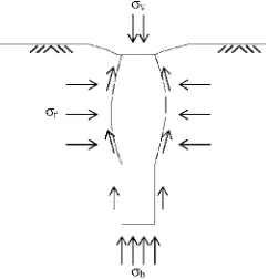
con-ditions and soil strengths. The granular column technique provides improved load bearing capacity and increased stiffness, and conse-quently, reduced settlements. Upon loading, granular columns de-velop end bearing and side frictional resistance in a similar fashion as piles. Granular columns also expand transversely and therefore acquire shear resistance from the surrounding soil共Fig. 1 Hughes and Withers 1974兲. The additional lateral stress due to column bulging enhances consolidation of the clay and further bulging of the column. Overall performance of the composite structure is con-trolled by the lateral support provided by the surrounding clay, which typically increases with depth. A better understanding of how granular columns contribute to the improved performance of soft clays in relation to bearing capacity and particularly settlement performance needs an improved testing protocol, which forms the basis of the paper.
In general, laboratory-based research has been invaluable to in-crease the understanding of granular columns. While many re-searchers may argue the relevance of 1 g laboratory model tests, it must be appreciated that for research and development purposes they are a cost effective and viable approach to preliminary inves-tigation. Progress, in terms of laboratory, analytical, and full-scale
Manuscript received June 17, 2005; accepted for publication January 24, 2006; published online February 2006.
1
Research Student, School of Civil Engineering, Queen’s University Belfast, Belfast United Kingdom.
2
Senior Lecturer, School of Civil Engineering, Queen’s University Belfast, Belfast United Kingdom.
3
Professor Emeritus, Geoenvironmental Engineering Centre, J. N. Technical University, Hyderabad, India.
4
[image:1.612.380.501.583.709.2]Lecturer, Department of Civil Engineering, National University of Ireland, Galway.
FIG. 1—Stresses during loading of a vibrated stone column共Hughes and With-ers 1974兲.
Geotechnical Testing Journal, Vol. 29, No. 3 Paper ID GTJ14195 Available online at: www.astm.org
共 兲
because of complex stress systems involved. In addition, samples have been tested under undrained conditions on the assumption that short-term stability is more critical than the long-term stability in relation to bearing capacity considerations. Any analysis with re-spect to settlement predictions using these tests can be difficult for various reasons. Consideration of settlement will necessitate an “effective stress analysis.” Controlling both total stress共foundation load and the surcharge兲 and pore water pressure in laboratory model testing is not easy, particularly when the clay bed is con-tained in a one-dimensional loading chamber. Controlling pore water pressure in a one-dimensional loading chamber would re-quire a tight seal between the loading piston and the loading cham-ber. This will inevitably generate additional frictional resistance be-tween the two components, and consequently, on the consolidation pressure applied on the sample共McKelvey 2002兲. These shortcom-ings often prevail not only in testing of granular columns, but also in other model studies in relation to piles and shallow foundations 共Anderson et al. 1991兲. This paper describes an innovative testing setup and procedure to approach the above issue.
Equipment and Validation Procedures
Dual Loading System
[image:2.612.322.556.56.228.2]As part of a research program to study the settlement characteris-tics and behavior of granular columns, it was necessary to design and construct equipment to overcome the experimental difficulties 共Hughes and Withers 1974; McKelvey 2002兲as indicated in the above paragraph. The challenge in the proposed research is to ad-vance the technology to examine the settlement performance of footings supported on soft clay reinforced with granular columns 共McKelvey et al. 2004兲. Particular significance of the equipment relies on its ability to test large samples consolidated under Ko con-ditions while applying the foundation load independently. Figure 2 shows a schematic illustration of the proposed loading arrange-ment. The objective was to control both vertical and horizontal stresses acting on the sample to maintain Kocondition during the consolidation process and then apply an independent foundation load via the footing that forms a part of the top cap placed at the top of the sample.
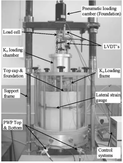
Figure 3 shows the newly developed dual loading triaxial sys-tem. The system is capable of testing 300-mm diameter by 400-mm high samples. Although this increased sample size may not appear as a significant advancement to represent near full-scale
testing, it represents an overall volume increase of 18 times greater than a standard 100-mm diameter and 200-mm triaxial samples. A large triaxial cell was designed based on the configuration of the standard cell incorporating special features to meet the criteria of
FIG. 2—Proposed loading configuration and test setup.
[image:2.612.330.555.321.713.2]testing soft clay samples reinforced with granular piles. The top and bottom plates of the large triaxial cell were manufactured from alu-minum, 25-mm thick and 550 mm in diameter. The bottom plate contains the usual terminals to connect cell pressure and drainage lines. An aluminum spacer ring attached to the base provides greater height within the cell and incorporates nine outlets for the various instrumentations required within the cell. The top plate in-tegrates a dual loading system that is capable of applying a vertical stress onto the sample to achieve a Koloading condition and apply an independent foundation loading on the reinforced clay bed via a 60-mm diameter footing located within the top cap.
Additional details of this particular arrangement are shown in Fig. 4. The footing is housed and fastened to the top plate. The re-taining cap is perforated with four small weep holes that allow cell pressure to act on the back of the footing during initial consolida-tion and Koloading. This ensures a uniform pressure distribution along the rigid top plate and prevents a vacuum being created when foundation load is applied. The design also incorporates features that will allow Koloading to be equally applied on the footing area. The footing is instrumented with two pressure cells, one located at the center of the footing and the other located closer to the footing boundary. A third pressure cell is located away from the footing and measures the vertical stress of the surrounding soil. The electrical cables are taken out of the footing using a special arrangement.
Application of cell pressure will subject the sample to isotropic compression. Koloading is achieved by controlling both vertical and horizontal pressures using pneumatic controllers. The lateral strain gage located at 1 / 3 sample height is used to ensure zero lat-eral strain during Koloading. Note here that the lateral strain gage will also examine the boundary effects of the granular columns dur-ing foundation loaddur-ing. The authors accept that to ensure a Ko con-dition and to monitor full boundary concon-ditions a lateral strain pro-file should be measured along the entire height of the sample. However, the critical location for lateral expansion is coupled with column budging which is known to be concentrated on the upper part of the granular column in the soft clay共Balaam 1978; Muir Wood et al. 2000兲. The Koloading system operates using the tech-nique of a rolling diaphragm attached to a piston and a loading ram. The loading ram extends on both sides of the Kochamber. The ram that protrudes inside the large cell is attached to athree-legged plate that rests within a locating recess on the top cap placed on the sample.
Foundation load is applied by operating a pneumatic loading
de-vice located at the supporting frame共Fig. 3兲. A thin slender loading ram is located inside the larger loading ram 共designated for Ko loading兲 that extends through the test chamber. This rod is sup-ported on linear bearings, which reduces friction and ensures free-fall under its own weight, though “O” rings are used to prevent leaks. A digital image of the entire system is shown in Fig. 5.
Samples are consolidated to required vertical and horizontal ef-fective stresses. A 1-L volume change unit is used to measure the sample volume change during the consolidation, Ko, and founda-tion loadings. An addifounda-tional feature incorporated in the system is the ability to generate a hydraulic gradient between the top and bot-tom of the sample and to allow the sample to attain a variable strength along the length. This will help model and represent to some extent the field condition where the strength of the soil in-creases with depth in normally consolidated clays.
The newly developed system is complex and has numerous de-vices that provide continuous monitoring of the sample throughout the duration of test. The devices include: five pressure traducers 共10 bar range兲, three pressure cells 共XPM10 range 0 – 20 bar ob-tained from FGP sensors, France兲, calibrated two LVDTs共5 cm and 2 cm stroke lengths兲, one internal strain gage 共5 cm travel dis-tance兲, one differential pressure transducer 共used in 1 L volume change unit兲, load cell共5 kN兲, and two pneumatic pressure control-lers to apply Koand foundation loadings. These devices facilitate the loadings to be applied gradually in ramped fashion at a given rate. All these transducers are read by a 16 channel-data logger 共MPX 3000兲integrated with WinHOST V4.31. A special housing was made to calibrate the pressure cells used by Geotechnical Digi-tal Device共GDS兲. The quality of the pressure measurements ob-tained using these pressure cells is good共Navaneethan 2003兲.
Sampling Technique
[image:3.612.58.283.54.232.2]The research uses commercially available kaolin for making samples. Samples are prepared by consolidating 35 kg of kaolin
[image:3.612.342.538.57.316.2]FIG. 4—Section showing top cap and foundation detail共not to scale兲.
powder mixed at a water content of 105 %; that is approximately 1.5 times the liquid limit 共LL= 70 %; Black 2003兲 in a one-dimensional mold共Fig. 6共a兲兲. Note here that the samples are pre-pared under rigid lateral boundary conditions. Sivakumar et al. 共2002兲reported a procedure to prepare samples from slurry state under flexible boundary conditions. However, this approach is too tedious to be considered in large size samples. Nevertheless, when the samples are reconsolidated in the large triaxial cell it is assumed that the stress levels that are used in the large triaxial cell are suffi-ciently high to eliminate any one-dimensional loading history that might have existed in the sample.
It is always a concern how to make quality large samples for testing. The standard approach used by many researchers is the ar-rangement where a rolling convoluted belloframe is attached to the piston. This particular technique works satisfactorily in short con-solidation chambers; however, researchers have reported a number of difficulties while using this method in larger diameter chambers 共Anderson et al. 1991; Navaneethan 2003; McKelvey 2002兲. An innovative method to produce large diameter triaxial samples is adopted in the present research. Given the large volume change that would occur during consolidation it was important to ensure that the chamber accommodates the initial volume of slurry required to produce a sample of 400 mm final height. The consolidation cham-ber was fabricated from a high performance polyethylene共HPPE兲 mains water pipe,共BS EN ISO 9002: 1994兲internal diameter共ID兲 295 mm, outside diameter共OD兲360 mm. The pipe was machined to leave an ID of 300 mm, OD of 350 mm and height of 900 mm. A wall thickness of 25 mm ensures the pipe has the capability of withstanding pressures of up to 800 kPa.
The top and bottom plates used to seal the chamber were manu-factured from aluminum and have dimensions of 420-mm diameter by 25-mm thick and are connected with six steel tie rods of 12-mm diameter. The base plate allows for drainage and incorpo-rates a 6-mm thick filter sheet with a diameter of 295 mm recessed flush with its surface. The top plate incorporates two air lines: one to apply consolidation pressure and the other to inflate the stabiliz-ing bush. The piston rod is a 25-mm diameter smooth brass rod and is connected to the piston plate. It is this piston plate that comprises a new innovative design to eliminate the problems associated with using a rolling belloframe.
This plate was manufactured from PVC and has dimensions of 298-mm diameter by 60-mm thickness. A “c” shaped groove was formed on the side wall of the piston plate, into which a universal
rubber tube共225 kPa兲 and loading chamber 共150 kPa兲 provides successful sealing with the chamber side wall and reduces the risk of consolidation pressure being lost.
Fully consolidated samples are extruded from the consolidation chamber and trimmed to size in preparation for column installation 共Fig. 6共c兲兲. Granular columns are installed into preformed holes using wet compaction of uniformly graded basalt共90 % of the ma-terial having 1 – 1.5 mm particle sizes兲. The holes are formed by helical augers that are mounted onto a special manufactured drill-ing rig. The rig consists of an electric motor that maintains a con-stant drill speed of 19 r / min and a rack and pinion mechanism that controls vertical movement. Previous studies 共Sivakumar et al. 2002兲have shown this to be a high quality, repeatable method for column installation. The uniformity of the column was monitored by measuring the density of the column along the length.
Test Procedure
This paper evaluates the complex testing system developed to per-form a series of tests to examine and understand the perper-formance of a foundation supported on granular columns. Initial results ob-tained confirm the accuracy and functionality of the newly devel-oped system. A consolidated sample was placed into the triaxial system and was initially subjected to an isotropic effective consoli-dation pressure of 75 kPa. This was then followed by Koloading whereby the vertical and the horizontal pressures were increased slowly to 125 kPa and 100 kPa, respectively, representing a Ko value of 0.8. This value is slightly higher than Kofor normally con-solidated kaolin共Navaneethan 2003; Burland 1990兲. Back pressure in the sample was maintained at 200 kPa all the time. Foundation loading was applied by ramping pressure in the pneumatic control-ler at a rate of 0.8 kPa/ h. The rate of loading is sufficient to achieve a fully drained loading condition. Foundation loading typically lasts 2 – 3 weeks; this allows an overall foundation displacement of between 15– 20 mm. It is difficult to ascertain the termination point for each test as the loading is stress controlled. This procedure is repeated to examine samples with various conditions, three of which are presented in this paper.
Results
[image:4.612.74.267.57.221.2]The research outlined as part of the program is in progress and as stated previously the purpose of this paper is only to highlight the development of the new dual-loading triaxial system for testing the performance of granular columns in relation to settlement control.
This paper uses results obtained from three tests; T1, T2, and T3. The conditions applied in these tests were for foundation loading on—T1, unreinforced soft clay; T2, clay reinforced with a single 25-mm diameter column of 125-mm length, and T3, clay rein-forced with a single 25-mm diameter column 250-mm long. The latter two tests correspond to length to diameter ratios of 6 and 10, respectively. The results to date validate the equipment and indicate that the study has the potential to alter how future model studies are conducted and provide significant developments in the understand-ing of the settlement performance of vibrated stone columns.
Samples
For the three samples discussed here, initial water content of the clay after consolidation was approximately 50.5 % with a variation of 0.2 %. In each sample an attempt was made to measure the varia-tion of water content along the sample length. The results have shown that the water content at the bottom of the sample was about 0.75 % higher than at the top. This may be attributed to side friction between the consolidation chamber and the clay. The implication of this is that not all the consolidation pressures applied at the top of the sample are transferred to the bottom of the chamber. Drainage during the consolidation of the slurry in the consolidation chamber was allowed only through the bottom of the chamber. Drainage through both top and bottom boundaries can accelerate the consoli-dation process considerably. However, the process will inevitably generate a complicated stress variation along the sample length. For example, if consolidation is allowed from both top and bottom, the clay close to the two boundaries will consolidate quickly, and con-sequently, the partly or fully consolidated clay close to the top boundary will act as a buffer restricting the pressure being applied to the clay underneath.
Foundation Loading
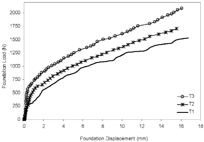
Figure 7 shows the foundation load-displacement responses for the unreinforced and reinforced samples. The loading was stress
con-trolled and applied at a rate of 0.8 kPa/ h to ensure a fully drained condition. The results indicate that at a footing displacement ofs = 10 mm the load carrying capacity of the unreinforced deposit was 1.25 kN. This increased to 1.4 kN and 1.6 kN, respectively. This represents an increase of 12 and 28 % for the composite samples of T2 and T3, respectively. The 25-mm diameter column represents an area replacement ratio共As兲of 17 %. In relation to the settlement consideration, the sample with no column exhibited a footing settlement of 6.5 mm at a foundation load of 1 kN. This settlement reduced to 4.5 mm and 2.2 mm in the case of 125-mm long and 250-mm long columns at the same loading condition. These re-duced settlements correspond to settlement reduction factors of 0.69 and 0.34 for T2 and T3, respectively.
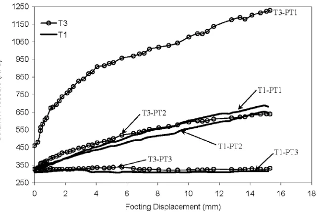
[image:5.612.140.469.54.283.2]The load-sharing mechanism of the composite clay/gravel col-umns was examined by analyzing the pressures measured by the pressure cells located beneath the footing. Figure 8 relates the pres-sure cells located under the foundation and away from it共PT1: cen-ter and directly on the granular column, PT2: underneath the foot-ing but away from the column, and PT3: located away from the footing兲. The results have been shown for tests performed on the unreinforced sample 共T1兲 and on a sample reinforced by a 125-mm共T2兲and 250-mm共T3兲long granular column 25 mm in diameter. The primary difference shown in Fig. 8 relates to the pres-sure transmitted onto the longer column in T3 in which the vertical pressure on the top of the column was approximately 1100 kPa at a footing displacement ofs= 10 mm. In the same test, the pressure read by PT2 was approximately 600 kPa which is nearly the same as that on the unreinforced sample at the same footing displace-ment. This corresponds to a stress ratio of共vg⬘ /vc⬘兲of 1.86. This ratio is somewhat smaller than expected; however, it should be noted that共a兲the area replacement ratio adopted in this particular test is only 17 %, and共b兲the stress ratios are usually high during undrained loading and will reduce with the clay carrying more load as the consolidation process progresses. It should be noted here that the boundary condition at the top of the sample共including the foot-ing area兲is rigid and therefore there will be pressure variation re-gardless of whether or not granular columns are present in the sample.
At the end of each test, the columns were exhumed to examine visually the deformation patterns. This revealed that the shorter column had no distinct variations in column diameter compared to the longer column, which showed significant deformations in the upper region. The shorter column of 125-mm long remained some-what unchanged; however, the longer 250-mm column showed signs of overall compression. Coupling the excavated column pro-files with the information presented in Figs. 7 and 8, it may be as-sumed that there was a reduced load transfer to the lower sections of the longer column since no deformation was observed. These results correspond to previous research conducted by共Hughes and Withers 1974兲where they stated that longer columns fail by bulg-ing and shorter columns penetrate into the underlybulg-ing soft clay bed and fail in end bearing resistance.
In the present study, the circumference boundary of the sample is flexible. Research has shown that the ratio between the diameter
of the sample and the footing, Ds/ Df, may have to be greater than five to avoid boundary effects. Some experimental evidence ob-tained by the lateral strain gage attached to the sample substantiates this claim. Figure 9 displays the lateral displacements recorded dur-ing the foundation loaddur-ings of T1, T2, and T3. Lateral displacement is represented by an increase or decrease in radius of the sample. Figure 9 shows the difference in lateral displacement of the unrein-forced and reinunrein-forced samples when the footing was loaded to be approximately 0.075 mm at a footing displacement of 10 mm. This change in diameter can be considered insignificant given the size of the sample and suggests that the Ds/ Dfis sufficiently large to avoid boundary effects.
[image:6.612.149.470.54.268.2]Based on the above information, it may be argued that the 125-mm long column in T2 was too short; however, using the same interpretation, the 250-mm long column in T3 may be overly con-servative. It may be concluded that the optimum column length in
[image:6.612.145.469.500.719.2]FIG. 8—Pressures read by PT1, PT2, and PT3 during foundation loading.
this situation may be between L/d ratios of 6 to 10. However, future studies investigating column lengths beyond 250 mm will substan-tiate this aspect. The preliminary work agrees with studies con-ducted by Hu共1995兲and McKelvey共2002兲who reported similar findings for optimizing column length; however, their proposals re-late to bearing capacity rather than to settlement.
In all three tests, the pressure cell located at PT3 read similar values, of the order of 315 kPa. The initial pressures appeared to rise slightly during early loading up to a footing displacement of 6 mm; beyond this point the pressure leveled off and remained con-stant. This may be a consequence of surface heave due to founda-tion plunge. Heave is restricted as the top plate共away from the foot-ing兲represents a rigid boundary surface while also maintaining a Koload. It is reasonable to assume that some additional stress con-centration will form around the immediate proximity of the plung-ing foundation; however, this reduces exponentially with increased distance from the center.
The experimental results presented serve to validate the func-tioning of the newly developed triaxial setup and the innovative ap-proach to produce large diameter samples. Further analysis of the results is beyond the scope of this paper. As the study is ongoing recommendations cannot be declared until additional tests relating to various L/d ratios, area ratios, single and multiple column con-ditions are performed. The development of such tests would im-prove numerical modeling of stone columns and provide increased confidence in their design.
Concluding Remarks
This paper discusses an innovative design of a large triaxial test setup and one-dimensional consolidation chamber developed to ex-amine the settlement characteristics of a foundation supported on soft clays reinforced with a single or a group of stone columns. Tests are conducted on large samples of 300-mm diameter by 400-mm high under drained conditions. Preliminary results vali-date the accuracy and functionality of the system. This equipment produces high quality test data that will lead to an improved testing protocol for future studies on ground improvement. A limitation of the test system is that the top plate on the sample represents a rigid boundary condition. Modifications for future studies may incorpo-rate a flexible boundary condition. This would enhance the versatil-ity of the system and allow the effect of differential settlement and surface heave to be evaluated.
Acknowledgments
The authors would like to thank Keller Ground Engineering, UK, for funding for the project, Department of Education and Learning 共DEL兲, Northern Ireland, and The Institution of Engineers Ireland 共IEI兲, who provided a research scholarship to Mr. J. Black. VJ Tech Ltd. manufactured the triaxial test setup. Mr. T. Crothers and his team in the Mechanical Workshop at Queen’s University, Belfast, fabricated the consolidation chamber.
Anderson, W. F., Pyrah, I. C., and Fryer, S., 1991, “A Clay Calibra-tion Chamber for Testing Field Devices,”Geotech. Test. J., Vol.
14, No. 4, pp. 440–450.
Balaam, N. P., 1978, “Load Settlement Behaviour of Granular Piles,” Ph.D. Thesis, University of Sydney, Australia.
Black, J. A., 2003, “Influence of Preparation Techniques on the Index Properties of Clay,” B.Eng. dissertation project, Depart-ment of Civil Engineering, Queen’s University, Belfast. Burland, J. B., 1990, “On the Compressibility and Shear Strength
of Natural Clays,”Geotechnique, Vol. 40, No. 3, pp. 329–378. Hughes, J. M. O. and Withers, N. J., 1974, “Reinforcing of Soft
Cohesive Soils with Stone Columns,”Ground Eng., Foundation Publications Limited, May, pp. 42–49.
Hu, W., 1995, “Physical Modeling of Group Behaviour of Stone Column Foundations,” Ph.D. Thesis, University of Glasgow. McKelvey, D., 2002, “Performance of Vibro Stone Column
Foun-dations in Deep Soft Ground,” Ph.D. Thesis, Queen’s University, Belfast.
McKelvey, D., Sivakumar, V., Bell, A., and Graham, J., 2004, “A Laboratory Model Study of the Performance of Vibrated Stone Columns in Soft Clay,”J. Geotech. Eng., Vol. 152, pp. 1–13. Muir Wood, D., Hu, W., and Nash, D. F. T., 2000, “Group Effect in
Stone Column Foundations: Model Tests,”Geotechnique, Vol. 50, No. 6, pp. 689–698.
Navaneethan, T., 2003, “Pre-yield Characteristics and Earth Pres-sure Coefficient of Over Consolidated Clays,” Ph.D. Thesis, Queen’s University, Belfast.
Serridge, C. J., 2004, “The Use of Reclaimed/Recycled Material in Vibro Stone Column Ground Improvement Techniques,” Pro-ceedings 5th International Conference on Ground Improvement Techniques, pp. 273–280.