• Table of
Contents
• Index
Cisco Secure Internet Security Solutions
By Andrew G. Mason, Mark J. Newcomb
Publisher : Cisco Press
Pub Date : May 30, 2001
ISBN : 1-58705-016-1
Pages : 528
Must-have security strategies using Cisco's complete solution to network security.
• The only book to cover interoperability among the Cisco Secure product family to provide the holistic approach to Internet security
• The first book to provide Cisco proactive solutions to common Internet threats
• A source of industry-ready pre-built configurations for the Cisco Secure product range
Cisco Systems strives to help customers build secure internetworks through network design featuring its Cisco Secure product family. Cisco Secure Internet Security Solutions covers the basics of Internet security, and then concentrates on each member of the Cisco Secure product family, providing a rich
explanation with examples of the preferred configurations required for securing Internet connections. The Cisco Secure PIX Firewall is covered in depth from an architectural point of view, and a reference of the PIX commands explains their use in the real world. Although Cisco Secure Internet Security Solutions is primarily concerned with Internet security, the information inside is also applicable to many general network security scenarios.
Copyright
Copyright© 2001 Cisco Press
Cisco Press logo is a trademark of Cisco Systems, Inc.
Published by:
Cisco Press
201 West 103rd Street
All rights reserved. No part of this book may be reproduced or transmitted in any form or by any means, electronic or mechanical, including photocopying, recording, or by any information storage and retrieval system, without written permission from the publisher, except for the inclusion of brief quotations in a review.
Printed in the United States of America 1 2 3 4 5 6 7 8 9 0
Library of Congress Cataloging-in-Publication Number: 00-105222
Warning and Disclaimer
This book is designed to provide information about Cisco Secure. Every effort has been made to make this book as complete and as accurate as possible, but no warranty or fitness is implied.
The information is provided on an "as is" basis. The authors, Cisco Press, and Cisco Systems, Inc. shall have neither liability nor responsibility to any person or entity with respect to any loss or damages arising from the information contained in this book or from the use of the discs or programs that may accompany it.
The opinions expressed in this book belong to the authors and are not necessarily those of Cisco Systems, Inc.
Trademark Acknowledgments
All terms mentioned in this book that are known to be trademarks or service marks have been appropriately capitalized. Cisco Press or Cisco Systems, Inc. cannot attest to the accuracy of this information. Use of a term in this book should not be regarded as affecting the validity of any trademark or service mark.
Feedback Information
At Cisco Press, our goal is to create in-depth technical books of the highest quality and value. Each book is crafted with care and precision, undergoing rigorous development that involves the unique expertise of members from the professional technical community.
Readers' feedback is a natural continuation of this process. If you have any comments regarding how we could improve the quality of this book, or otherwise alter it to better suit your needs, you can contact us through e -mail at [email protected]. Please make sure to include the book title and ISBN in your message.
We greatly appreciate your assistance.
Credits
John Wait
Editor-in-Chief
John Kane
Cisco Systems Program Manager
Bob Anstey
Managing Editor
Patrick Kanouse
Development Editor
Andrew Cupp
Project Editor
Marc Fowler
Copy Editor
Ginny Kaczmarek
Technical Editors
Sean Convery
Masamichi Kaneko
Duane Dicapite
Joel McFarland
Steve Gifkins
Brian Melzer
Per Hagen
Ruben Rios
Joe Sirrianni
Tom Hua
John Tiso
Team Coordinator
Tammi Ross
Book Designer
Gina Rexrode
Cover Designer
Louisa Klucznik
Production Team
Argosy
Indexer
Larry D. Sweazy
Corporate Headquarters
Cisco Systems, Inc.
170 West Tasman Drive
San Jose, CA 95134-1706
USA
http://www.cisco.com Tel: 408 526-4000
800 553-NETS (6387)
Fax: 408 526-4100
Cisco Systems Europe
11 Rue Camille Desmoulins
92782 Issy-les-Moulineaux
Cedex 9
France
http://www-europe.cisco.com Tel: 33 1 58 04 60 00
Fax: 33 1 58 04 61 00
Americas Headquarters
Cisco Systems, Inc.
170 West Tasman Drive
San Jose, CA 95134-1706
USA
http://www.cisco.com Tel: 408 526-7660
Fax: 408 527-0883
Asia Pacific Headquarters
Cisco Systems Australia, Pty., Ltd
Level 17, 99 Walker Street
North Sydney
NSW 2059 Australia
Fax: +61 2 9957 4350
Cisco Systems has more than 200 offices in the following countries. Addresses, phone numbers, and fax numbers are listed on the Cisco Web site at
www.cisco.com/go/offices
Argentina • Australia • Austria • Belgium • Brazil • Bulgaria • Canada • Chile • China •
Colombia • Costa Rica • Croatia • Czech Republic • Denmark • Dubai, UAE • Finland • France • Germany • Greece • Hong Kong • Hungary • India • Indonesia • Ireland • Israel • Italy • Japan • Korea • Luxembourg • Malaysia • Mexico • The Netherlands • New Zealand • Norway • Peru • Philippines Poland • Portugal • Puerto Rico • Romania • Russia • Saudi Arabia • Scotland • Singapore • Slovakia • Slovenia • South Africa • Spain • Sweden • Switzerland • Taiwan • Thailand • Turkey • Ukraine • United Kingdom • United States • Venezuela • Vietnam • Zimbabwe
Copyright © 2000, Cisco Systems, Inc. All rights reserved. Access Registrar, AccessPath, Are You Ready, ATM Director, Browse with Me, CCDA, CCDE, CCDP, CCIE, CCNA, CCNP, CCSI, CD-PAC, CiscoLink, the Cisco NetWorks logo, the Cisco Powered Network logo, Cisco Systems Networking Academy, Fast Step, FireRunner, Follow Me Browsing, FormShare, GigaStack, IGX, Intelligence in the Optical Core, Internet Quotient, IP/VC, iQ Breakthrough, iQ Expertise, iQ FastTrack, iQuick Study, iQ Readiness Scorecard, The iQ Logo, Kernel Proxy, MGX, Natural Network Viewer, Network Registrar, the Networkers logo, Packet, PIX, Point and Click Internetworking, Policy Builder, RateMUX, ReyMaster, ReyView, ScriptShare, Secure Script, Shop with Me, SlideCast, SMARTnet, SVX, TrafficDirector, TransPath, VlanDirector, Voice LAN, Wavelength Router, Workgroup Director, and Workgroup Stack are trademarks of Cisco Systems, Inc.; Changing the Way We Work, Live, Play, and Learn, Empowering the Internet Generation, are service marks of Cisco Systems, Inc.; and Aironet, ASIST, BPX, Catalyst, Cisco, the Cisco Certified Internetwork Expert Logo, Cisco IOS, the Cisco IOS logo, Cisco Press, Cisco Systems, Cisco Systems Capital, the Cisco Systems logo, Collision Free, Enterprise/Solver, EtherChannel, EtherSwitch, FastHub, FastLink, FastPAD, IOS, IP/TV, IPX, LightStream, LightSwitch, MICA, NetRanger, Post-Routing, Pre -Routing, Registrar, StrataView Plus, Stratm, SwitchProbe, TeleRouter, are registered trademarks of Cisco Systems, Inc. or its affiliates in the U.S. and certain other countries.
All other brands, names, or trademarks mentioned in this document or Web site are the property of their respective owners. The use of the word partner does not imply a partnership relationship between Cisco and any other company. (0010R)
Dedications
—Andrew Mason
This work is dedicated to my lovely wife, Jacqueline, without whose help I could never have accomplished as much as I have.
—Mark Newcomb
About the Authors
Andrew G. Mason, CCIE #7144, CCNP Security, and CCDP, is the CEO of CCStudy.com Limited (www.ccstudy.com), a United Kingdom-based Cisco Premier Partner specializing in Cisco consulting for numerous United Kingdom-based companies. The CCStudy.com web site is a fast-growing online Cisco community for all of the Cisco Career Certifications.
Andrew has 10 years of experience in the network industry and currently is consulting for Energis -Squared, the largest ISP in the United Kingdom. He is involved daily in the design and implementation of complex secure hosted solutions, using products from the Cisco Secure product range.
Mark J. Newcomb, CCNP Security and CCDP, is a senior consulting network engineer for Aurora Consulting Group (www.auroracg.com), a Cisco Premier Partner located in Spokane, Washington, USA. Mark provides network design, security, and implementation services for clients throughout the Pacific Northwest.
Mark has more than 20 years of experience in the microcomputer industry. His current projects include designing secure communication systems for wireless devices and providing comprehensive security services to the banking industry.
About the Technical Reviewers
Sean Convery is a network architect in Cisco's VPN and Security business unit. He has been at Cisco for three years. Prior to that he held positions in both IT and security consulting during his six years in the network security industry.
Steve Gifkins is a CCIE and CCSI of four and five years, respectively. He is based in the United Kingdom, where he runs his own independent Cisco-only consulting and training business. He is married with no children, and his hobbies include anything to do with outdoor life. Having retired with a knee injury from playing active sports such as squash, rugby, and soccer, he has taken up new hobbies in horse eventing and show jumping. In addition, he enjoys skiing and hill scrambling.
involving Fortune 500 clients. As a member of the Wolfpack, Brian received his undergraduate degree in electrical engineering and his master's degree in management at North Carolina State University.
John Tiso, CCIE #5162, is one of the chief technologists of NIS, a Cisco Systems Silver Partner. He has a bachelor's degree from Adelphi University, Garden City, New York. John also holds the CCDP certification, the Cisco Security specialization, the Cisco Voice Access
specialization, and Sun Microsystems, Microsoft, and Novell certifications. John can be reached by e-mail at [email protected].
Acknowledgments
I would like to thank Mark Newcomb for working on this book with me. We live at different ends of the world and have only met once, but still have built a long-lasting friendship. My thanks also go out to John Kane, Andrew Cupp, and the rest of the Cisco Press team for pulling all of this together and providing an editorial service that is second to none. The technical reviewers, John Tiso, Brian Melzer, and Steve Gifkins, helped us both a lot with the technical direction of the text, thanks to you all. I would like to thank Sean Convery and Bernie Trudel for allowing us to include their excellent white paper as an invaluable reference in this book.
Finally, I would like to thank Sean Convery, Duane Dicapite, Per Hagen, Jeff Hillendahl, Tom Hua, Masamichi Kaneko, Joel McFarland, Ruben Rios, and Joe Sirrianni. This group of Cisco employees provided helpful feedback that immensely improved the quality of this book.
—Andrew Mason
As with all works of any consequence, this book was not simply the work of two authors. There were a great number of individuals behind the scenes that made this work a reality. I would like to list a few.
I want to acknowledge the technical reviewers, Steve Gifkins, Brian Melzer, and John Tiso, all superior engineers. These three individuals showed us where we did not cover enough
material, showed us where we were unclear, and provided a large number of suggestions that added to the quality of this work. Their efforts are truly appreciated.
I thank Andrew Cupp and John Kane at Cisco Press for their ceaseless pursuit of the best possible work. They, along with many others at Cisco Press, have provided us with everything necessary to successfully complete this book.
I would also like to express my gratitude to Sean Convery and Bernie Trudel for letting us use their Cisco SAFE white paper as a reference in this book.
I want to thank Sean Convery, Duane Dicapite, Per Hagen, Jeff Hillendahl, Tom Hua,
Finally, I want to thank Andrew Mason for all of his work on this book. Even though we live on opposite sides of the world, I consider him one of my best friends.
—Mark Newcomb
Introduction
The Internet is a core business driver for many large corporations. Along with the expanded business, however, come security issues. Recent news headlines often feature articles about large e-commerce sites getting hacked, with potentially disastrous results.
Cisco Systems strives to help customers build secure internetworks through network design that features its Cisco Secure product family. At present, no available publication deals with Internet security from a Cisco perspective, using the Cisco Secure product family. This book covers the basics of Internet security and then concentrates on each member of the Cisco Secure product family, providing a rich explanation with examples of the preferred
configurations required for securing Internet connections.
The book starts by explaining the threats posed by the Internet and progresses to a
complete working explanation of the Cisco Secure product family. The individual
components of the Cisco Secure product family are discussed in detail, with advice given
about how to configure each individual component to meet the requirements of the
situation. The Cisco Secure PIX Firewall is covered in-depth, from presenting an
architectural point of view to providing a reference of the common PIX commands and
their use in the real world. Although the book is concerned with Internet security, it is
also viable for use in general network security scenarios.
Audience
Cisco Secure Internet Security Solutions is for network engineers and network designers. The primary audience is network engineers and network designers responsible for the corporate Internet connection or the installation of Cisco Secure products. The secondary audience is other networking staff members that have an interest in security or Cisco Secure products in relation to their specific corporate environment.
Also, CCIE and CCDP/CCNP candidates will take interest in the title to improve their Internet security skills.
The book should be read and used by an intermediate to advanced reader. Because of the unique content, industry experts could reference this book.
Audience Prerequisites
protocol TCP/IP, and a familiarity of the topics covered in the Cisco Press books
Internetworking Technologies Handbook
and
IP Routing Fundamentals
.
What Is Covered
The book is organized into 11 chapters and one appendix:
• Chapter 1 "Internet Security"— This chapter provides a historical overview of the Internet and the growing number of risks that are associated with it.
• Chapter 2 "Basic Cisco Router Security"— This chapter looks at Cisco routers and the related security threats and vulnerabilities from an Internet point of view. Sample configurations and tips are provided for implementation on your corporate Internet routers.
• Chapter 3 "Overview of the Cisco Security Solution and the Cisco Secure Product
Family"— This chapter provides an overview of the Cisco Security Solution and the Cisco Secure product range. The following six chapters look at each device in more detail.
• Chapter 4 "Cisco Secure PIX Firewall"— This chapter covers the Cisco Secure PIX Firewall. A technical overview of the PIX is provided, along with a configuration guide and sample configurations based against a case study.
• Chapter 5 "Cisco IOS Firewall"— This chapter looks at the Cisco IOS Firewall. Sample configurations are provided, and the major technologies are explained.
• Chapter 6 "Intrusion Detection Systems"— This chapter looks at one of the latest and most emergent security technologies, intrusion detection. It gives a brief explanation of the various types of intrusion detection systems, and then provides configurations for both a Cisco router and a Cisco Secure PIX Firewall based on perimeter intrusion detection.
• Chapter 7 "Cisco Secure Scanner"— This chapter covers the Cisco Secure Scanner. A brief explanation of network scanning and its uses, good and bad, is provided before looking in-depth at the offering from Cisco, the Cisco Secure Scanner.
• Chapter 8 "Cisco Secure Policy Manager (CSPM)"— This chapter covers the Cisco Secure Policy Manager. The CSPM provides a centralized management platform for an enterprise network that incorporates Cisco routers running the Cisco IOS Firewall and Cisco Secure PIX Firewalls. This chapter provides a sample installation and configuration of CSPM.
• Chapter 9 "Cisco Secure Access Control Server (ACS)"— This chapter looks at the Cisco Secure Access Control Server and its uses within an internetwork. Configuration guidelines are provided for both the network access server (NAS) and the Cisco Secure ACS server component.
• Chapter 11 "Providing Secure Access to Internet Services"— This chapter focuses on Internet services and the protection that can be offered to them. The chapter is written with servers hosted either at an ISP or on the corporate DMZ in mind. Each Internet service is looked at individually, and potential vulnerabilities and remedies are proposed.
• Appendix A "Cisco SAFE: A Security Blueprint for Enterprise Networks"— The principle goal of SAFE, Cisco's secure blueprint for enterprise networks, is to provide best practice information to interested parties on designing and implementing secure networks. SAFE serves as a guide to network designers considering the security requirements of their networks. SAFE takes a defense-in-depth approach to network security design. This type of design focuses on the expected threats and their methods of mitigation, rather than on "put the firewall here, put the intrusion detection system there" instructions. This strategy results in a layered approach to security, where the failure of one security system is not likely to lead to the compromise of network resources. SAFE is based on Cisco products and those of its partners.
Command Syntax Conventions
Command syntax in this book conforms to the following conventions:
• Commands, keywords, and actual values for arguments are bold. • Arguments (which need to be supplied with an a ctual value) are italic.
• Optional keywords or arguments (or a choice of optional keywords or arguments) are in brackets, [ ].
• Choice of mandatory keywords or arguments is in braces, { }.
NOTE
Device Icons Used in the Figures
Figure I-1 contains a key of the most important device icons used in the figures in this book.
Part I: Internet Security Fundamentals
Part I Internet Security Fundamentals
Chapter 1 Internet Security
Chapter 1. Internet Security
This chapter contains the following sections:
• Internet Threats • Network Services
• Security in the TCP/IP Suite • Denial of Service (DoS) Attacks • Creating a Corporate Security Policy • Summary
• Frequently Asked Questions • Glossary
This chapter introduces some of the basics of network security. It starts with a brief description of some of the most common forms of attacks. Next, the chapter describes the characteristics of several types of network devices.
The Cisco Secure IOS software is specifically designed to prevent attacks from affecting your network. Cisco Secure provides the highest levels of protection from unauthorized access, denial of service (DoS) attacks, man-in-the-middle attacks, and many other common methods used either to deny service or to obtain unauthorized information. The Cisco Secure IOS relies on a number of configuration techniques, hardware solutions, and technologies, including the Adaptive Security Algorithm (ASA). These provide the best security available to the network administrator today.
As technologies evolve, Cisco continuously refines its hardware and software solutions to remain on the cutting edge of network security. This book explores the methods of protecting the network that are available through use of the Cisco Secure solutions.
To set the foundations necessary for preventing attacks, the first chapter covers the format of several protocols, including Transmission Control Protocol (TCP), Internet Protocol (IP), Address Resolution Protocol (ARP), and User Datagram Protocol (UDP). The more common forms of DoS attacks are then examined. Specific techniques for dealing with DoS attacks are provided in later chapters.
This chapter concludes by examining the need for and use of a corporate security policy.
Internet Threats
book is designed to show the administrator how to design networks that are resistant to attack.
There are a number of ways that the data on a corporate network can be compromised. Among them are the following:
• Packet sniffing— In this method, the attacker uses a packet sniffer to analyze the data for sensitive information traveling between two sites. One example is to use a packet sniffer to discover username and password combinations.
• IP address spoofing— In this method, an attacker changes the source IP address of packets to pretend to be a trusted user or trusted computer.
• Port scans— This method determines the ports on a network device where a firewall listens. After the attacker discovers the weaknesses, attacks are concentrated on applications that use those ports. Port scans can be launched against firewalls, routers, or individual computers.
• DoS attack— The attacker attempts to block valid users from accessing a resource or gateway. This blockage is achieved by sending traffic that causes an exhaustion of resources.
• Application layer attack— This method attempts to exploit weaknesses in server software to obtain the permission of the account that runs an application or to limit use of the system through a DoS attack.
• Trojan horse— In this method, the user is made to run a malicious piece of software. The Trojan horse attack uses an apparently safe application or data packet to
transport destructive data to the recipient. After the destructive data has reached its destination, the program or script launches, causing damage. Trojan horse attacks can exploit technologies such as HTML, Web browser functionality, and the Hypertext Transfer Protocol (HTTP). These attacks include Java applets and ActiveX controls to transport programs across a network or load them on user Web browsers.
Network Services
At this point, it is important for you to understand some security services available on
networks. Each of these services is fully discussed later in this book. The following services are discussed within this chapter in a general manner. There is overlap among these services; for example, basic authentication services are included on all Cisco routers. Therefore, this section should be referred to only for general guidelines.
Router Services
Although this is a rudimentary way to protect a network, it is still effective in limited
circumstances. The problem with relying on this technique is that it does not scale well in large installations; it is static and can be overcome by a persistent attacker. Most network
administrators need more granularity in their security settings than simply to allow or disallow traffic to a network.
When more flexibility is needed, administrators rely on the second way that routers can provide security services on a network: access lists. Four main types of access lists are used on Cisco equipment:
• Standard
• Extended
• Reflexive
• Context-based Access Control (CBAC)
Standard access lists allow or deny packets based only on the source address of the packet. Extended access lists are more extensible, allowing filtering based on source or destination address, in addition to protocol, ports used, and whether the connection is already
established.
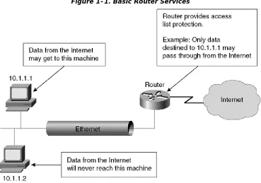
Reflexive access lists dynamically change in response to outgoing requests for data. As a local host establishes a connection by requesting data, the access list attached to the inbound interface changes to allow returning packets through. Once the session is closed, returning packets are again denied access. Context-based Access Control (CBAC) is used with a limited number of programs to allow ports to open and close dynamically based on the needs of that particular application. Figure 1-1 gives an example of basic router services. Each of these types
Figure 1-1. Basic Router Services
Firewall Services
Firewall services tend to be more sophisticated than routing services. One example of this is the granularity of packet filtering on a firewall compared with a router without the firewall operating system.
On a router, it is not unusual to use the keyword established in extended access lists; this keyword is only useful while working with connection-oriented protocols. The keyword
established does not allow for protocols such as UDP where there is no connection.
Additionally, the keyword established merely checks to ensure that the data packet is formatted to look like there has been a connection established. The Cisco Private Internet Exchange (PIX) Firewall, on the other hand, actually checks to make sure that data from a host has gone outbound before allowing data inbound.
The Cisco PIX Firewall that will be discussed in Chapter 4, "Cisco Secure PIX Firewall," filters both
connection-oriented and connectionless protocols based on whether a host inside has
Figure 1-2. Firewall Services
Authentication and Authorization Services
Authentication refers to the process of ensuring that a claimed identity of a device or end user is valid. Authorization refers to the act of allowing or disallowing access to certain areas of the network based on the user, system, or program. Both services can be provided through either a Remote Access Dial-In User Service (RADIUS) or a Terminal Access Controller Access Control System (TACACS) server. Encryption is also available for authentication and can run on a firewall or a router. Figure 1-3 shows an example of authorization services implemented on
a network.
[image:19.612.127.491.461.676.2]Network Address Translation (NAT) Services
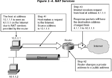
Many corporate networks choose to hide their local-area network addresses from all outside users. Network Address Translation (NAT) changes the local Layer 3 IP network addresses, generally called private addresses, to what are generally called global or public addresses. This translation can occur at a router or on a firewall. There are both security and practical
[image:20.612.119.494.255.517.2]advantages to using NAT. The security advantage is that attacks cannot be made directly to the end device, because the NAT device must translate each packet before forwarding that packet to or from the end device. The practical advantage is that NAT is easily done at both firewalls and routers, allowing the corporation to use a large number of public IP addresses without being forced to purchase more than a handful of private IP addresses. NAT is defined by RFC 1631. Figure 1-4 shows an example of a network employing NAT.
Figure 1-4. NAT Services
Encryption and Decryption Services
Encryption is the act of changing the content of data in a way that prevents recognition of that data without reversing the encryption process. The reversing of the encryption process is called decryption. Encryption and decryption services can be accomplished on end devices, routers, and firewalls.
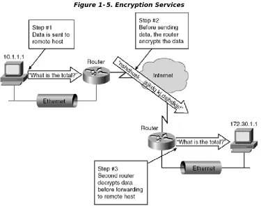
A Virtual Private Network (VPN) is created when an encrypted connection is established through a public packet network. A VPN can be established between two hosts at different locations, between two networks of the same company, or between the networks of two different companies. Figure 1-5 shows how encryption services can secure data through the
Figure 1-5. Encryption Services
Proxy Services
Figure 1-6. Proxy Services
Now that you have looked at some of the basic security services available on networks, you can move on to the next section to see how TCP/IP pertains to security issues.
Security in the TCP/IP Suite
To understand security issues regarding the TCP/IP protocol suite, you first need to
understand how TCP/IP works. This section will explore how TCP/IP works before going on to explore how the protocol suite can be used in attacks against a network.
Overview of TCP/IP
TCP/IP was originally developed by the U.S. Defense Advanced Research Projects Agency (DARPA) to interconnect Department of Defense (DoD) computers. The objective of the DARPA project was to build a robust communications p rotocol able to recover automatically from any node or communications failure. This reliability and recovery from node failure, which was necessitated by the fact that communications needed to be maintained under battlefield conditions, spawned the creation of the Internet.
TCP/IP is the predominant routed protocol suite used within the Internet. Virtually all of the major software and hardware manufacturers offer support for the full TCP/IP protocol suite.
TCP and IP in the Open System Interconnection (OSI)
Model
The Open System Interconnection (OSI) model consists of seven layers. Each of these seven layers interacts and communicates with the layers directly above and directly below it.
functionality of the DoD model can be mapped closely to the functionality of the OSI reference model, as shown in Figure 1-7.
Figure 1-7. The Seven-Layer OSI Model and the Four-Layer DoD Model
The following list of the DoD layers further explains their mapping to the OSI model:
• Application/process layer— The DoD application/process layer defines the upper layer functionality included within the application, presentation, and session layers of the OSI model. Support is provided for application communications, code formatting, session establishment, and maintenance functions between applications.
• Host to host layer— The DoD host-to-host layer maps directly to the transport layer of the OSI model. The transport layer defines connectionless and connection-oriented transport functionality. Host-to-host is the DoD layer where TCP resides. The transport layer is the OSI layer where TCP resides.
• Internet layer— The DoD Internet layer maps directly to the network layer of the OSI model. The network layer defines internetworking functionality for routing protocols. This layer is responsible for the routing of packets between hosts and networks. The Internet layer is where IP resides in the DoD model. The network layer is the OSI layer where IP resides.
• Network layer— The DoD network interface layer maps to the data link and physical layers of the OSI model. Data link properties, media access methods, and physical connections are defined at this layer. Please note the very different functions of the DoD network layer (listed in this bullet) and the OSI network layer (called the Internet layer in the DoD model).
Within the TCP/IP suite, there are several different protocols in addition to IP and TCP. Figure 1-8
shows where each of these protocols sits in relation to the OSI model.
Figure 1-8. The Seven-Layer OSI Model and TCP/IP
Internet Protocol (IP)
IP, the network layer datagram service of the TCP/IP suite, is used by all other protocols in the TCP/IP suite except the address resolution protocol (ARP) and the reverse address resolution protocol (RARP) to transfer packets from host to host over an internetwork. This function isn't supported by any other protocols contained within the TCP/IP suite. The other main feature of IP, congestion control, is found on nearly every layer of the OSI model. IP performs basic congestion control that is very primitive in comparison with that offered by the TCP.
Routing is described as the delivery of packets or datagrams from the source node to the destination node across multiple intermediate networks. When hosts reside on the same physical network, they can be delivered using the routing services provided within their own IP modules. When hosts are located on separate connected networks, the delivery is made through routers that connect the networks.
IP is controlled by RFC 791, which defines the set of rules for communicating across the internetwork. Addressing and control information that allows the IP packets to be routed to their intended destination over the internetwork is included.
The two primary rules defined by RFC 791 relate to
• A connectionless, best-effort packet delivery service routing across an internetwork.
IP pro vides a connectionless, best-effort packet delivery system. From a logical point of view, this service has three characteristics that are important for understanding the behavior of IP routing. These three characteristics are as follows:
• Connectionless protocol— IP is classified as a connectionless protocol. Each packet is delivered independently of all other packets. The packets might be sent along different routes and might arrive at their destination out of sequence. No
acknowledgements are sent or received to indicate that the IP packets were received by the intended destination.
• Unreliable delivery— Because IP is a connectionless protocol, it is also classified as an unreliable protocol. IP cannot guarantee that any packet transmitted will be received b y the host intact or in the original sequence in which it was sent. IP has no provision for notification that a packet is dropped en route to the destination.
• Best-effort delivery— IP uses its best effort to deliver the packets to their intended destination. IP only discards a packet when it is forced to do so because of hardware issues, such as resource allocation problems, or errors caused at the physical layer. If an error occurs while a packet is being sent, IP attempts to retransmit the packet.
IP packets or datagrams consist of the IP header and the data. The data is received from the upper layer protocols such as TCP or UDP, and encapsulated into the IP packet. The IP header is created by IP and is used by IP on intermediary systems to route the packet to its final destination. The IP header contains information to enable IP to route the packet independent of any other process.
IP Header Datagram Format
Figure 1-9 shows the format of an IP datagram header. The IP datagram header contains a
number of items that are interesting to the administrator who is concerned with security issues. Throughout this book, you'll see references to datagrams with various attributes, such as a fragmented IP datagram. This section explains how these packets are formed and the relevance of a field's settings.
A list of the fields in Figure 1-9 and their functions follows:
• Version— The version field is 4 bits and represents the IP version for this packet. Most systems use IP version 4. In the future, most systems will use IP version 6 (IPv6) or IP: The Next Generation (IPng).
• IP Header Length (IHL)— The IHL field defines the length of the IP header. The options field that is discussed later in this list is optional and can affect the length of the header. The IHL field occupies 4 bits of the IP header.
• Type of service (ToS)— The ToS field occupies 8 bits of the IP header. This field specifies how both hosts and intermediate devices should handle the packet. This field can also be broken down further into subfields. These subfields contain information on precedence, delay, throughput, reliability, cost, and MBz.
• Total length— The total length field occupies 16 bits in the IP header. This field contains 16 bits specifying the total length of the IP packet up to 65,535 bytes.
• Identification— The identification field occupies 16 bits in the IP header. This field, used in conjunction with the flag and offset fields, is used in the packet fragmentation and reassembly process.
A packet needs to be fragmented, or broken down, when the original packet size is larger than the MTU at the receiving node or any router along the route. IP breaks the original packet into smaller packets that are within the MTU limitations. Each
fragmented packet is a true IP packet and contains both an IP header and IP data.
A unique number is entered into the 16-bit identification field. If the packet is
• Flags— The flags field occupies 3 bits of the IP header. Its only purpose is in fragmentation. Each bit is interpreted independently as follows:
-
Bit 0—
Bit 0 is reserved and not used.
-
Bit 1—
Bit 1 is the Don't Fragment or DF bit. When this bit is
cleared (value of 0), it is an indicator that the packet can be
fragmented. When the bit is set (value of 1), it indicates that the
packet cannot be fragmented.
-
Bit 2—
Bit 2 is the More Fragments or MF bit. When this bit is
cleared (value of 0), it indicates that this is the last fragment of
the packet. When the bit is set (value of 1), it indicates that
more fragments are to follow.
• Fragment offset— The fragment offset field occupies 13 bits of the IP header. This field identifies the offset of this portion of the original packet before it was fragmented.
• Time To Live (TTL)— The TTL field occupies 8 bits of the IP header. This field specifies how long the packet can exist before being dropped or copied to the bit bucket by an intermediate router. When a router receives a packet it decrements the TTL value by 1. If this value is 0, the route r discards the packet by copying it to the bit bucket; otherwise it forwards the packet to the next hop router or to the destination network if the destination network is directly connected. This method ensures that an IP packet will eventually be dropped if there is a routing loop somewhere in the network.
• Protocol— The protocol field occupies 8 bits of the IP header. This field is used to identify the upper layer protocol that should receive the data contained in the packet. The 8-bit field facilitates 255 different protocols that are represented as numeric values.
Table 1-1 lists the protocol assignments for IP.
Table 1-1. IP Protocol Numbers
Value
Keyword
Protocol
0
HOPOPT
Hop-by-hop option (IP version 6)
1
ICMP
Internet Control Message Protocol
2
IGMP
Internet Group Management Protocol
3
GGP
Gateway-to-Gateway Protocol
4
IP
IP in IP Encapsulation
5
ST
Stream
6
TCP
Transmission Control Protocol
8
EGP
Exterior Gateway Protocol
9
IGP
Interior Gateway Protocol
10
BBN-RCC-
MON
BBN RCC Monitoring Protocol
11
NVP-II
Network Voice Protocol version II
12
PUP
PUP
13
ARGUS
ARGUS
14
EMCON
EMCON
15
XNET
Cross Net Debugger
16
CHAOS
CHAOS
17
UDP
User Datagram Protocol
18
MUX
Multiplexing
19
DCN-MEAS
DCN Measuring Subsystems Protocol
20
HMP
Host Monitoring Protocol
21
PRM
Packet Radio Measurement
22
XNS-IDP
Xerox NS IDP
23
TRUNK-1
Trunk-1
24
TRUNK-2
Trunk-2
25
LEAF-1
Leaf-1
26
LEAF-2
Leaf-2
27
RDP
Reliable Data Protocol
28
IRTP
Internet Reliable Transaction Protocol
29
ISO-TP4
ISO Transport Protocol (Class 4)
30
NETBLT
Bulk Data Transfer Protocol
31
MFE-NSP
MFE Network Services Protocol
32
MERIT-INP
Merit Inter-Nodal Protocol
33
SEP
Sequential Exchange Protocol
34
3PC
Third Party Connection Protocol
35
IDRP
Inter-Domain Routing Protocol
36
XTP
XTP
37
DDP
Datagram Delivery Protocol
38
IDPR-CMTP
Inter-Domain Routing Protocol Control
Message Transport Protocol
39
TP++
TP++ Transport Protocol
40
IL
IL Transport Protocol
41
IPv6
Internet Protocol version 6
43
IPv6-ROUTE Routing Header (IP version 6)
44
IPv6-FRAG
Fragment Header (IP version 6)
45
IDRP
Inter-Domain Routing Protocol
46
RSVP
Reservation Protocol
47
GRE
General Routing Encapsulation Protocol
48
MHRP
Mobile Host Routing Protocol
49
BNA
BNA
50
ESP
Encapsulation Security Payload
51
AH
Authentication Header (IP version 6)
52
I-NLSP
Integrated Net Layer Security Protocol
53
SWIPE
Encrypted IP
54
NARP
NBMA Address Resolution Protocol
55
MOBILE
IPO Mobility
56
TLSP
Transport Layer Security Protocol
(Kryptonet Key Management)
57
SKIP
Skip
58
IPv6-ICMP
Internet Control Message Protocol (IP
version 6)
59
IPv6-NoNxt
No Next Header (IP version 6)
60
IPv6-Opts
Destination Options (IP version 6)
61
HOST
Local Host
62
CFTP
CFTP
63
NETWORK
Local Network
64
SAT-EXPACK SATNET and Backroom EXPACK
65
KRYPTOLAN Kryptolan
66
RVD
MIT Remote Virtual Disk Protocol
67
IPPC
Internet Pluribus Packet Core
68
FILE
Distribute File System
69
SAT-MON
SATNET Monitoring
70
VISA
VISA
71
IPCU
Internet Packet Core Utility
72
CPNX
Computer Protocol Network Executive
73
CPHB
Computer Protocol Heart-Beat
74
WSN
Wang Span Network
78
WB-MON
Wideband Monitor
79
WB-EXPAK
Wideband EXPAK
80
ISO-IP
ISO Internet Protocol
81
VMTP
VMTP
82
SECURE-
VMTP
Secure VMTP
83
VINES
Banyan Vines
84
TTP
TTP
85
NSFNET-IGP NSFNET Interior Gateway Protocol
86
DGP
Dissimilar Gateway Protocol
87
TCF
TCF
88
EIGRP
Enhanced Interior Gateway Routing
Protocol
89
OSPFIGP
OSPF Interior Gateway Protocol
90
SPRITE-RPC Sprite Remote Procedure Call
91
LARP
Locus Address Resolution Protocol
92
MTP
Multicast Transport Protocol
93
AX.25
AX.25 Frames
94
IPIP
IP in IP Encapsulation
95
MICP
Mobile Internetworking Control Protocol
96
SCC-SP
Semaphore Communications Security
Protocol
97
ETHER-IP
Ethernet in IP Encapsulation
98
ENCAP
Encapsulation Header
99
ENCRYPT
Private Encryption Schemes
100
GMTP
GMTP
101
IFMP
Ipsilon Flow Management Protocol
102
PNNI
PNNI over IP
103
PIM
Protocol Independent Multicast
104
ARIS
ARIS
105
SCPS
SCPS
106
QNX
QNX
107
AN
Active Networks
108
IPPCP
IP Payload Compression Protocol
109
SNP
Sitara Network Protocol
111
IPXIP
IPX in IP Encapsulation
112
VRRP
Virtual Router Redundancy Protocol
113
PGM
PGM Reliable Transport Protocol
114
NOHOP
Zero Hop Protocols
115
L2TP
Layer 2 Transport Protocol
116
DDX
D-II Data Exchange
117–
254
UNASSIGNED Unassigned
255
RESERVED
Reserved
• Header checksum— The header checksum field occupies 16 bits of the IP header. This field is calculated as a checksum for the IP header only.
• Source address— The source address occupies 32 bits of the IP header. Under normal circumstances, this is the actual 32-bit IP address of the source node.
• Destination address— The destination address occupies 32 bits of the IP header. Under normal circumstances, this is the actual 32-bit IP address of the destination node.
• Options— The options field is an optional field following the destination address. If present, it contains the security, timestamp, and special routing subfields:
-
Security—
The security subfield specifies the security level and
distribution restrictions.
-
Timestamps—
The timestamps subfield contains a 32-bit value.
This value is normally set to the number of milliseconds since
midnight universal time.
-
Special routing—
The special routing subfield specifies either
host-discovered paths or the specific path that the datagram
should travel.
• Padding— The padding field always contains zeros. This field is used to round the length of the IP header until it contains an exact multiple of 32 bits.
Address Resolution Protocol (ARP)
The Address Resolution Protocol (ARP) is defined by RFC 1122. ARP creates an interface between the data link layer and the network layer of the OSI model. The primary function of ARP is to resolve IP addresses to network layer addresses, such as a Media Access Control (MAC) address.
Routers and hosts both use ARP to resolve IP addresses to MAC addresses. All network
layer address such as a MAC address is required for this to take place. The MAC address corresponding to the IP address can be either statically entered prior to communications by entering a static ARP entry, or dynamically learned by ARP.
To learn a MAC address dynamically, ARP sends out a broadcast frame requesting the MAC address of a host with a specified IP address. All hosts on the segment receive the broadcast, but only the host with the specified IP address responds with its MAC address. At this point, Layer 3 communication can begin. Reverse ARP (RARP), which is used to translate a MAC address to an IP address, uses the same header format as ARP.
The header of an ARP packet differs depending on the underlying networking technology in use. The header fields of an ARP packet contain values specifying the lengths of the successive fields. A list of fields follows:
• Hardware type— Indicates the type of hardware in use.
• Protocol type— Indicates the network level protocol.
• Hardware address length— Indicates the length of the hardware address in bytes.
• Protocol address space— Indicates the length o f the protocol address in bytes.
• Operation code— Indicates the operation for this packet: ARP request, ARP response, RARP request, or RARP response.
• Sender's hardware address— Indicates the hardware address of the sender.
• Sender's protocol address— Indicates the network layer address of the sender.
• Target hardware address— With a RARP request, this contains the destination hardware address. With a RARP response, this carries both the destination's hardware and network layer addresses.
• Target protocol address— With an ARP request, this carries the destination's network layer address. With an ARP response, this carries both the destination's hardware and network layer addresses.
Internet Control Message Protocol (ICMP)
ICMP messages are encapsulated within IP packets. Using a connectionless, unreliable transfer mechanism, ICMP is used to report errors within a network. Usually, only higher-level
protocols are encapsulated within another protocol. However, ICMP is an integral part of the IP protocol suite that still is encapsulated within the data portion of an IP packet. RFCs 792 and 1700 define ICMP.
protocol using IP is carried within these first 8 bytes, this helps with detecting what caused the error.
The formats of echo request, echo reply, and destination unreachable messages are shown in
Figure 1-10. Remember that this ICMP message is imbedded within the data portion of an IP
packet, which is in turn encapsulated within another protocol, such as Ethernet.
Figure 1-10. ICMP Message Formats
The main use of ICMP is to provide a reporting function that identifies error conditions on network devices. Routers usually generate ICMP messages as they receive and route the IP packet. These ICMP messages contain three fields at the beginning of the packet:
• Type field— The type field is an 8 -bit field that identifies the message. These type field values are displayed in Table 1-2.
Table 1-2. ICMP Type Field Values
Type Value
Message Type
0
Echo Reply
1
Unassigned
2
Unassigned
3
Destination Unreachable
4
Source Quench
5
Redirect
6
Alternate Host Address
7
Unassigned
8
Echo Request
9
Router Advertisement
10
Router Selection
11
Time Exceeded
12
Parameter Problem
13
Timestamp Request
15
Obsolete (Information Request)
16
Obsolete (Information Reply)
17
Address Mask Request
18
Address Mask Reply
19–29
Reserved
30
Traceroute
31
Datagram Conversion Error
32
Mobile Host Redirect
33
IPv6—Where Are You?
34
IPv6—Here I am.
35
Mobile Registration Request
36
Mobile Registration Reply
37–255
Reserved
• Code field— The code field is an 8-bit field that provides further information about the ICMP message.
• Checksum field— The checksum field is a 16-bit field that is used to verify the integrity of the whole ICMP message.
Transmission Control Protocol (TCP)
TCP, defined in RFC 761, operates at the transport layer of the OSI model. TCP encapsulates IP and provides a connection-oriented and reliable transport protocol. Services using TCP include Hypertext Transfer Protocol (HTTP), Simple Mail Transport Protocol (SMTP), Post Office Protocol 3 (POP3), and File Transfer Protocol (FTP).
Figure 1-11. TCP Header Format
An explanation of each of the fields in the TCP header follows:
• Source port— The source port is 16 bits and contains the value of the source port where data originates. Because both UDP and TCP use ports, a list of valid source ports is included within the UDP section.
• Destination port— The destination port is 16 bits and contains a value of the source port to which data is sent.
• Sequence number— The sequence number is 32 bits. The value of this field is the sequence number of the first data octet within this segment when the SYN bit is not set. When the SYN bit is set, the value of this field is the Initial Sequence Number (ISN), and the first data offset is set to ISN + 1.
• Acknowledgement number— The acknowledgement number is 32 bits long. Once a connection is established, this field always contains a value equal to the next sequence number expected by the receiver. A connection is assumed to be established if the ACK bit is set.
• Data offset— The data offset field is 4 bits in length and specifies the number of 32-bit words within the TCP header, thereby specifying where the data begins.
• Reserved— This unused field is 6 bits in length and is set to 0.
• Flags (control bits)— The flags field is also known as the control bits field. This field is 6 bits in length and contains the following subfields, each a length of 1 bit:
- URG— Urgent pointer field significant
- RST— Reset connection request
- SYN— Synchronize sequence numbers
- FIN— Connection finished
• Window size— The 16-bit window size field contains the number of data octets that the sender is willing to receive.
• Checksum— The 16-bit checksum field contains the data calculated during the cyclic redundancy check (CRC). This checksum is used for checking the data integrity for the TCP packet, including the source address, destination address, protocol, options, and TCP length.
• Urgent pointer— The 16-bit urgent pointer field is used in conjunction with the URG control bit. If the URG control bit is set, the urgent pointer field contains the sequence number of the octet following the urgent data.
• Options— The options field is variable in length aligning to an equal multiple of 8 bits. An option within this field begins on an 8 -bit boundary. The option field can be
formatted as a single octet. An alternative format is the combination of an option followed by an octet describing the option length and the option data octets.
• Maximum segment size— The optional 16-bit maximum segment size field is only used on packets with the SYN control bit set. This field contains the maximum receive segment size of the sender.
• Padding— The variable length padding field is used to ensure that the TCP header ends on a 32-bit boundary. This field always contains zeros.
User Datagram Protocol (UDP)
UDP is defined in RFC 768 and operates at the transport layer of the OSI model. UDP is a simple packet-oriented transport layer protocol that is connectionless and therefore unreliable. The UDP datagram resides within the data portion of an IP packet.
UDP packets are sent with no sequencing or flow control, so there is no guarantee that they will reach their intended destination. The receiving host compares the UDP header checksum, and if a problem is detected, the packet is dropped without reporting the error back to the sending host.
This is a very fast transport protocol because no acknowledgements or advanced sequencing are carried out at the transport layer. Upper layer protocols can enforce their own error detection and recovery to utilize the speed of UDP. UDP is typically used when the data is not essential, such as in video or voice streaming live content over the Internet. The Trivial File Transfer Protocol (TFTP) that is used to upgrade software images on Cisco routers and switches is also based on UDP. A breakdown of the UDP header fields is shown in Figure 1-12.
Denial of Service (DoS) Attacks
A DoS attack is designed to overwhelm the victim's network to the point that the victim cannot use the network for legitimate business purposes. A Distributed DoS (DDoS) is simply a DoS that is launched simultaneously from more than one source. Sometimes these attacks are used in an attempt to confuse the equipment to a point where unauthorized access is able to penetrate inside the network. At other times, the attacks are launched merely because the perpetrator wishes to bring down the victim's network connections. In either case, there are some common methods used in DoS attacks that are explored in this chapter, in addition to ways to avoid becoming a victim of these attacks.
SYN Flood Attacks
To understand how a SYN flood attack can occur, you must first understand how a connection is established. When a host wishes to establish a connection, a TCP packet with the SYN bit set is sent to the remote host. The remote host looks at the port within this TCP packet. If the port corresponds to a service that is running, the remote host replies with another SYN
packet. The initiating host then sends an ACK packet that starts the data transfer stage of the communications.
Because there is no guarantee of how quickly the ACK packet will be received by the remote host, a partially opened connection, also called a half-open connection, is maintained by the remote host. Maintaining half-open connections uses CPU cycles and memory and exposes the remote host to an inherent vulnerability from SYN flood attacks.
In a SYN flood attack, the perpetrator repeatedly causes the remote host to maintain half-open connections. As the number of half-half-open connections increases, more memory and CPU cycles are used in an attempt to maintain these connections. Unless measures are taken to limit the time that each half-open connection is maintained or the total number of half-open connections permitted, eventually the remote host will spend all of its resources trying to maintain these connections. SYN flood attacks can be further understood through an explanation of the LAND.c attack.
One form of SYN flood attack is known as the LAND.c attack. Originally written in the C programming language, this form of attack can be devastating to unprotected systems. However, filtering spoofed addresses as discussed in Chapter 2, "Basic Cisco Router Security,"
will prevent this type of attack from being successful.
In the LAND.c attack, a perpetrator repeatedly sends TCP SYN packets to a known address. In the example shown in Figure 1-13, the perpetrator is launching an attack on a Web server. In this
example, the SYN packets would have both the source and destination address set to 10.1.1.30, which is the address of the machine under attack.
Figure 1-13. LAND.c Attack
Within the TCP packet, the perpetrator sets a port number. Any port number associated with a running service could be used. Because the attacked machine's main function is to service Web pages, the perpetrator is likely to set the port number to 80, which is used for Web services.
The attacked machine receives the SYN packet and checks the port requested. If the port requested is currently running a service, the attacked machine replies with another SYN packet to the "requesting host," attempting to complete the connection. In this case, the requesting host, as defined by the source address of the IP packet, is the same as the
destination host. Therefore, the attacked host tries to establish a connection with itself. While waiting for a response that will never come, the attacked host holds open a connection until a timeout period has passed. This timeout period varies, depending on the operating system of the attacked host.
Ping Attacks
A ping attack occurs when a perpetrator attempts to overwhelm the victim's equipment through the use of ICMP Echo Request packets. As with most DoS attacks, ping attacks attempt to use CPU cycles and memory to prevent legitimate use of equipment.
Although a number of ping attacks have been launched successfully, such as the ping of death and the smurf attacks, simple configuration changes can prevent attacks from adversely affecting your network. Chapter 2 shows how to configure Cisco routers to prevent becoming
vulnerable to these forms of attack. Following is an explanation of a smurf attack.
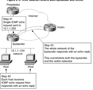
Smurf Attack
A smurf attack is when an attacker sends an ICMP Echo Request to a network address of an unsuspecting amplifier, rather than a specific host. The attacker enters the IP address of the targeted server as the ICMP echo source address. Every host on the amplifier network responds and sends an ICMP Echo Reply to the source address of the ICMP echo packet. This address is that of the server that the attacker wanted to attack. Because the amplifier network has many hosts, they each respond to the ICMP Echo Request, amplifying the number of ICMP Echo Replies received by the victim's host.
In this case, the attacker uses another's resources and network to attack the victim. This attack works by simply consuming bandwidth to the victim. Once this bandwidth is consumed, all access to the server from other public hosts will slowly grind to a halt.
Creating a Corporate Security Policy
A corporate security policy is a necessary piece of any network design effort. Security is as important to a network design as bandwidth requirements and choosing the network protocol. Failing to consider security during the design stage leads to situations where extra efforts must be taken to ensure safety. Security measures incorporated within the design are much easier to implement, generally less expensive, and usually more robust. The corporate security policy is a formal statement that specifies a set of rules that users must follow when gaining access to corporate assets.
You need to differentiate the security policy from the technical design of the security features. For example, a proper security policy does not state that a PIX 515 Firewall will be used on Internet connections. Instead, a well-formed security policy states that a firewall will be used on Internet connections and that this firewall will have certain minimum capabilities. The network security administrator chooses the best equipment and configurations to accomplish the goals, using the policy as a guide.
For a security policy to succeed, some general guidelines must be followed:
• Management must support the policy.
• The policy must be implemented globally throughout the company.
• The policy must clearly define responsibilities for users, administrators, and management.
• The policy must be flexible enough to adapt to changing technologies and company goals.
• The policy must be understandable.
• The policy must be widely distributed.
• The policy must be enforceable.
• The policy must provide sanctions for users violating the policies.
• The policy must contain a response plan for when security breaches are exposed.
Once a security policy is implemented, the company will see a number of benefits. Some of these benefits include:
• A framework from which all security efforts are built.
• Lessened uncertainty about whether an action is permissible.
• A basis for punitive action to be taken in cases of unacceptable network usage.
• A comprehensive system for auditing security efforts.
As defined in "The Site Security Handbook" (RFC 2196), a security policy does not dictate how a business runs. Rather, the business needs dictate the security policy. The policy does not dictate the exact equipment or configuration to be used; instead, it gives guidance to the administrator.
Summary
This chapter introduced some of the basics of network security. Starting with a brief
description of some of the most common forms of attacks, it quickly moved on to a description of common network devices.
Security provided by the TCP/IP protocol set was discussed, delving into the format of the more common protocols. Understanding the format and use of each of the fields within a protocol is necessary for the administrator to thwart attacks successfully. The chapter examined a few of the more common forms of DoS attacks. Specific examples of how to deal with each of these types of attacks will be shown in later chapters.
In this book, the focus of how to deal with and prevent attacks is on solutions provided by Cisco Secure.
Finally, the chapter covered the need for and re quirements of a corporate security policy. The remaining chapters of this book will build on the foundations within this chapter.
Question: Why do I really need a written security policy? Why can't I just secure my network?
Answer: Although this may seem reasonable for a smaller network, failing to implement a written security policy has many ramifications. First, the policy defines the goals and parameters around which the configurations are designed. Failing to write down the policy is similar to implementing a network before designing the network.
Second, as networks and technologies grow in complexity, you need a base reference to look back on in order to compare where you are to where you wish to be. The written security policy provides you with this information.
Finally, as network administrators are replaced or added to the workforce, the written policy gives new administrators guidance about how equipment should be configured. Having a single document to rely on allows new administrators to avoid guessing about what should be allowed and what should be denied.
Question: How secure should I make my network? Isn't there a point at which the network becomes unusable?
Answer: The security on a network must fit the corporation. A suit that is too tight is not comfortable; neither is one that is too loose. If the security is too tight, users will constantly complain. If the security is too loose, the network runs the danger of being hacked or exposed to a DoS attack. The task of the administrator is to find the middle ground that follows the policy, protects the network, and does not cause the users to complain. Again, this is where a well-defined written security policy comes in.
Question: My office network doesn't have any critical data. Do I still need to protect it?
Answer: Yes. Even if your own network does not have critical data, which is doubtful, there is another reason to protect the network. Failing to protect your own network might leave you in a position where your network is used to launch attacks on other networks. Protecting your own network prevents attackers from using it to launch attacks against others. Also, even if your data is not critical, your operation probably is, and a DoS attack will still be devastating.
Glossary
Glossary
ASA (Adaptive Security Algorithm)—
CBAC (Context-based Access Control)—
A Cisco proprietary method of allowing returning traffic through a router only after packets requesting that session have traveled out the same interface.
DoS (denial of service)—
A form of attack that attempts to deny the availability of a network or host, usually by overwhelming that network or host with requests.
NAT (Network Address Translation)—
NAT is the process where the source or destination address of IP packets is changed as these packets traverse a router or firewall. NAT allows a network using private IP addresses to connect to the Internet using public IP addresses.
RADIUS (Remote Access Dial-In User Service)—
A protocol used to authenticate users on a network.
TACACS (Terminal Access Controller Access Control System)—