Int. J. Electrochem. Sci., 13 (2018) 8170 – 8178, doi: 10.20964/2018.08.53
International Journal of
ELECTROCHEMICAL
SCIENCE
www.electrochemsci.orgA Comparative Study of Synthesis Processes for LiNi
0.5Mn
1.5O
4Cathode Material
Chao Ma1,*, Lei Wang2, Huanping Yang3,*, Hong Liu1 1
College of Electronic Engineering, Chengdu Technological University, Chengdu 611730, China 2
School of Environmental Science & Engineering, Shanghai Jiao Tong University, Shanghai 200240, China
3
Zhejiang University of Science & Technology, Hangzhou 310023, China *
E-mail: [email protected], [email protected]
Received: 25 April 2018 / Accepted: 18 June 2018 / Published: 5 July 2018
This work explores the preparation of LiNi0.5Mn1.5O4, a high voltage cathode material, using the rheological route and two conventional liquid-phase methods. The microstructure of the as-prepared powder materials and the electrochemical performances of LiNi0.5Mn1.5O4 electrodes are characterized by X-ray diffraction, scanning electron microscopy and electrochemical tests. Although the samples were synthesized through similar methods, the resulting electrochemical properties are quite different. The LiNi0.5Mn1.5O4 material synthesized via the rheological method not only shows a good cycle performance, but also exhibits the highest discharge capacity of 146.2 mAh g-1. This is mainly ascribed to the combination of solvents in the rheological process which speed up the dispersion and improve the mixability of the precursors, thus inducing the formation of small and uniform electrode particles.
Keywords: Lithium-ion battery, rheological method, cathode material, electrochemical property
1. INTRODUCTION
theoretical capacity of LiNi0.5Mn1.5O4 is 146.7 mAh g-1. Thanks to its high working potential, the energy density of LiNi0.5Mn1.5O4 is 20% higher than that of LiCoO2 [4]; this makes LiNi0.5Mn1.5O4 a promising cathode material for future electric vehicles or energy storage applications [5].
The cathode in lithium-ion battery is well known to rely on insertion/extraction reactions, in which lithium-ions are accommodated into an open host structure allowing for electron accumulation, and the following extraction process corresponds to the electron removal. The cathode material synthesis method plays a significant role in the sample structure and its electrochemical performance. A variety of synthetic methods have been reported for the preparation of cathode materials, including solid state reactions [6], sol-gel [7], co-precipitation [8], rheological [9], spray pyrolysis [10, 11], electrophoretic deposition and pulsed laser deposition [12, 13]. Depending on the preparation procedure, the final product will have a specific microstructure, particle size distribution and phase purity, which will play a vital role in its final electrochemical performance. Therefore, choosing the most appropriate method is essential to prepare high-performance cathode materials.
In this work, the LiNi0.5Mn1.5O4 cathode materials are synthesized via a modified rheological method and via two liquid-phase preparation processes for comparison. The relationship between the preparation route and the electrochemical properties are discussed in details.
2. EXPERIMENTAL
2.1 Materials synthesis
LiNi0.5Mn1.5O4 was prepared by using Li(CH3COO)·2H2O (AR, 99%), Ni(CH3COO)2·4H2O (AR, 99%) and Mn(CH3COO)2·4H2O (AR, 99%) with the molar ratio of Li: Ni: Mn of 1.05: 0.5: 1.5 (5% excess in molar ratio to compensate for the volatilization of Li during the calcination). The first synthesis route (S1 samples) was the rheological method. The raw materials containing 0.05 mol Li and other metal ions were mixed and grinded thoroughly. Then 10 mL ethanol/distilled water solution was added with the volume ratio of 1: 1, and the mixture was adjusted into a paste. Then, 5 mL of aqueous ammonia (AR, 25%) was added to the mixture and blended to form a brown paste. After being dried at 120 °C, the powders were grinded and compacted, and then calcined at 450 °C for 6 h and at 800 °C for 14 h in air, respectively. Finally, the sample was further annealed at 650 °C for 10 h to fully oxidize the Mn3+ into Mn4+ [14]. During the whole process, the heating/cooling rate was kept fixed to 5 °C/min.
The second procedure (S2 samples) was based on a liquid-phase method. The same precursor materials were added into 10 mL of distilled water and 5 mL of aqueous ammonia (AR, 25%). Then, a brown paste precursor was formed and let drying and calcinating following the same procedure used for the rheological route.
2.2 Materials characterization
The crystallization of LiNi0.5Mn1.5O4 powders was investigated by X-ray diffraction (XRD, Bruker D8). The morphology of the LiNi0.5Mn1.5O4 powders was investigated by scanning electron microscopy (SEM, Supra55VP, Zeiss).
2.3 Cell assembly and electrochemical tests
For the electrochemical testing, the cathode was prepared by pasting the slurry containing 80 wt% active materials, 10 wt% conductive carbon black and 10 wt% polyvinylidene fluoride dissolved in 1-methy-1-pyrrolidinone; the mixture was coated onto an Al foil and vacuum dried at 100 °C for 10 h. The electrochemical cells were assembled using the as-prepared cathode, a lithium metal foil counter electrode and porous polypropylene film (Celgard 2400) as separator. The electrolyte solution was 1 M LiPF6 in a solution of ethylene carbonate (EC) and dimethyl carbonate (DMC) (1: 1, v/v). The electrochemical characterization was performed on CR2025 coin-type half-cells in dry Ar-filled glove box.
Charge/discharge tests were performed on a multi-channel battery test system (BTS-51, Neware, China) at room temperature, in the range between 3.5 and 4.9 V and with the current density ranging from 0.2 C to 5.0 C (assuming the theoretical capacity of 150 mAh g-1). The cyclic voltammograms (CVs) were acquired on the CHI650C electrochemical workstation in the potential range from 3.5 to 4.9 V at the scan rate of 0.1 mV s-1.
3. RESULTS AND DISCUSSION
[image:3.596.134.468.491.710.2]3.1 Material characterizations
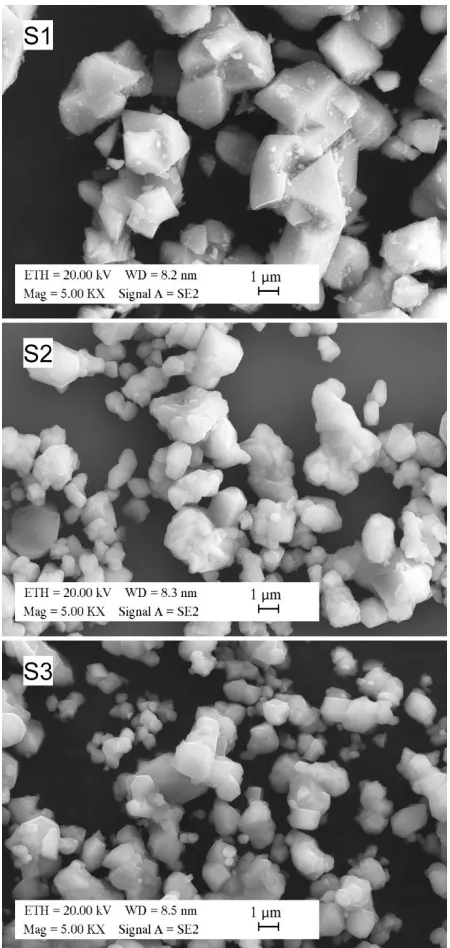
Figure 2. SEM images of LiNi0.5Mn1.5O4 powders obtained by the different preparation methods. The same magnification is applied in each image to compare the particle sizes.
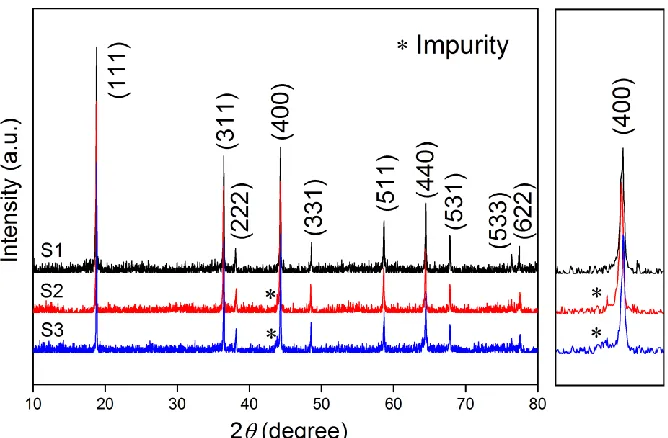
LiNixMn2-xO4 obtained by the liquid-phase method contained NiO impurity [15]. The authors proved that even if a stoichiometric amount of nickel was used in the liquid-phase synthetic process, an extra amount of non-bonded nickel was found in the LiNi0.5Mn1.5O4 powder which could not form the LiNi0.5Mn1.5O4 perfect solid solution and possibly lead to the formation of NiO or LixNi1-xO species as seen in the XRD patterns [16].
Fig. 2 shows the SEM images from LiNi0.5Mn1.5O4 samples: samples S2 and S3 show wide particle size distributions between 1 and 3 μm with irregular morphologies, while sample S1 exhibits a regular and homogeneous morphology with an average particle size of about 2 μm. This feature is ascribed to ammonia acting as a chelating agent and allowing the reactants to be mixed uniformly at the molecular level. In addition, the Mn2+ would possibly be oxidized to its higher valence state, which would allow to modify the precursor color. Ethanol was used as capping agent thanks to its large dipolar momentum [17], which can reduce the particle agglomeration when used as the solvent. Thus a sufficient dispersion was achieved during the mixture and the following drying procedures. In addition, acetates can dissolve in the distilled water easily and mixed much more sufficiently. The different dispersion and mixability of the precursors may have significant influences on the characteristics of the final products after the heat treatment. However, both S2 and S3 samples lack the required procedures.
3.2 Electrochemical performance
Figure 3. First charge-discharge curves at 0.2 C rate of LiNi0.5Mn1.5O4 electrodes. Two clear voltage plateaus around 4.7 V and 4.1 V can be seen in S1, S2 and S3.
[image:5.596.169.428.394.591.2][image:6.596.170.428.190.381.2]
materials. Such high discharge voltage not only enhances the energy density but also makes the material capable to be coupled with different anode materials which display better safety-related properties but require high voltage [19]. In addition, LiNi0.5Mn1.5O4 has a relatively high capacity which is similar to the mature commercial olivine LiFePO4 materials, for which the specific discharge at 0.2 C rate is about 162-164 mAh g-1, corresponding to 95.3-96.5% of the theoretical capacity (170 mAh g-1) [20]. However, for LiFePO4 cathodes the voltage plateau occurs at smaller values (~ 3.4 V).
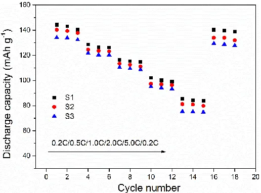
Figure 4. Discharge capacities of LiNi0.5Mn1.5O4 electrodes obtained by the three preparation methods at different discharge rates.
Fig. 4 reports the discharge capacity of LiNi0.5Mn1.5O4 electrodes at different rates. The procedure consists of applying 0.2, 0.5, 1.0, 2.0 and 5.0 C for three charge/discharge cycles followed by the final measurement at 0.2 C (both charge and discharge are performed at the indicated rates). It is not only possible to see the intercalation behavior of the cathode during different discharge rates, but also can understand whether the battery recovers its capacity after the long stress period [21]. Although the three materials are synthesized through similar methods, the electrochemical properties are sensibly different. At 5.0 C, the polarization induced deterioration is observed in the LiNi0.5Mn1.5O4 electrode [22]. The sample S1 displays the best electrochemical stability and reversibility. For S1 sample, the initial discharge capacity at 0.2, 0.5, 1.0, 2.0, 5.0 and 0.2 C rate is 144.2, 128.6, 116.4, 101.9, 85.3 and 140.3 mAh g-1, respectively. After 3 cycles, its discharge capacity at 0.2 C almost recovers to the initial value. For the other two samples (S2 and S3), and the LiMn0.8Fe0.2PO4/C composite the reversible capacity at 0.1, 0.2, 0.5, 1.0, 2.0, 5.0 and 0.1 C is 142, 123, 114, 103, 91, 69 and 126 mAh g -1
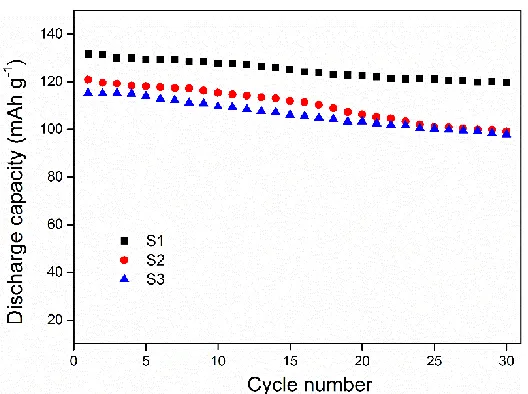
Figure 5. Discharge capacities of LiNi0.5Mn1.5O4 electrodes exposed to continuous cycling at 0.5 C.
Fig. 5 shows the evolution of the discharge capacity of LiNi0.5Mn1.5O4 electrodes upon continuous cycling (30 cycles at 0.5 C rate); S1 exhibits the highest discharge capacity and the best capacity retention during the cycling, with 91% of initial discharge capacity retained after 30 cycles and a capacity loss below 0.4 mAh g−1 per cycle. The discharge capacity loss is much higher in S3 (15%) and S2 (18%). For comparison, in a previous research, after 30 cycles at 0.1 C rate, the LiNi1/3Co1/3Mn1/3O2 nanofibers could only retain 88% of their initial discharge capacity [24]. Compared with cathode materials with layered structure, LiNi0.5Mn1.5O4 displays an excellent capacity retention ascribed to the Ni doped spinel LiMn2O4 structure in which the dissolution of Mn2+ into the electrolyte can be avoided [19].
[image:7.596.170.430.476.672.2]
Fig. 6 shows the CVs from LiNi0.5Mn1.5O4 electrodes between 3.0 and 5.3 V. For S1, S2 and S3 samples, the oxidation/reduction peaks occur at 4.53/4.87, 4.42/4.95 and 4.27/4.98 V vs. Li/Li+, corresponding to the voltage difference of 0.34, 0.53 and 0.71 V, respectively. The redox peaks in S1 show a relatively symmetric profile, indicating a good reversibility of the electrochemical reaction. The potential difference between the redox peaks is quite small and the area surrounded by the CVs is larger for S1 sample, indicating that the electrochemical polarization is relative weak [25]. These characteristics indicate that LiNi0.5Mn1.5O4 electrode synthesized by rheological method has the best electrochemical reversibility and battery reaction kinetics. The small and uniform particle size of LiNi0.5Mn1.5O4 allows for a large surface area which enables Li+ ions to enter the spinel crystal structure of LiNi0.5Mn1.5O4 electrode with a lower polarization [26]. The improved specific capacity and rate performance is also explained by the increase of efficiency of the electrochemical intercalation and de-intercalation of the Li+ ions in and out of the host materials thanks to the shorter path length [27].
4. CONCLUSIONS
In summary, LiNi0.5Mn1.5O4 cathode materials are successfully synthesized by rheological and liquid-phase methods and the effects of the synthesis conditions on the final structure, morphology and electrochemical performance have been compared. The modified rheological method uses a chelation reagent to enable the mixing at the molecular level using different reactants. This method leads to the most homogeneous particle size and better electrochemical properties. Small and uniform LiNi0.5Mn1.5O4 electrode particles show a lower agglomeration which can significantly improve the electrochemical stability and the ability to insert and extract much more lithium-ions and electrons efficiently during the cycling. Thus, the LiNi0.5Mn1.5O4 electrode synthesized via the rheological method shows best performance among the three methods in terms of rate capability, reversibility and capacity, in particular at high C-rate. These results demonstrate that LiNi0.5Mn1.5O4 cathode material with high performance can be realized by the improvement of production process.
ACKNOWLEDGEMENTS
This work was supported by the National Natural Science Foundation of China (No. 61504168 & No. 21501149), the Research Project of the Introduction Talent (No. 2017RC015).
References
1. M. Armand, J. M. Tarascon, Nature, 451 (2008) 652. 2. X. Liang, Int. J. Electrochem. Sci., 11 (2016) 4611.
3. Q. Zhong, A. Bonakdarpour, M. Zhang, Y. Gao, J. Dahn, J. Electrochem. Soc., 144 (1997) 205. 4. X. Fang, Y. Lu, N. Ding, X. Feng, C. Liu, C. Chen, Electrochim. Acta, 55 (2010) 832.
5. D. Crain, J. Zheng, C. Sulyma, C. Goia, D. Goia, D. Roy, J. Solid State Electr., 16 (2012) 2605. 6. H. S. Fang, Z. X. Wang, X. H. Li, H. J. Guo, W. J. Peng, J. Power Sources, 153 (2006) 174. 7. H. Liu, Y. Wu, E. Rahm, R. Holze, H. Wu, J. Solid State Electr., 8 (2004) 450.
Electrochem. Sci., 9 (2014) 7712.
9. Q. Liu, H. Liu, X. Zhou, C. Cong, K. Zhang, Solid State Ionics, 176 (2005) 1549. 10. S. H. Park, Y. K. Sun, Electrochim. Acta, 50 (2004) 439.
11. D. Li, A. Ito, K. Kobayakawa, H. Noguchi, Y. Sato, Electrochim. Acta, 52 (2007) 1919.
12. A. Caballero, L. Hernan, M. Melero, J. Morales, R. Moreno, B. Ferrari, J. Power Sources, 158 (2006) 583.
13. H. Xia, S. Tang, L. Lu, Y. Meng, G. Ceder, Electrochim. Acta, 52 (2007) 2822. 14. R. Santhanam, B. Rambabu, J. Power Sources, 195 (2010) 5442.
15. Y. S. Lee, Y. Todorov, T. Konishi, M. Yoshio, Electrochem. Commun., 4 (2002) 989.
16. S. Mukerjee, X. Yang, X. Sun, S. Lee, J. McBreen, Y. Ein-Eli, Electrochim. Acta, 49 (2004) 3373. 17. J. E. Martin, J. P. Wilcoxon, J. Odinek, P. Provencio, J. Phys. Chem. B, 104 (2000) 9475.
18. D. Guyomard, J. Tarascon, Solid State Ionics, 69 (1994) 222.
19. B. Xu, D. Qian, Z. Wang, Y. S. Meng, Mater. Sci. Eng. R, 73 (2012) 51.
20. L. Chen, Z. Chen, S. Liu, H. Zhang, Q. Huang, Int. J. Electrochem. Sci., 13 (2018) 5413.
21. J. Xiao, X. Chen, P.V. Sushko, M.L. Sushko, L. Kovarik, J. Feng, Z. Deng, J. Zheng, G.L. Graff, Z. Nie, Adv. Mater., 24 (2012) 2109.
22. T. Ohzuku, R. Yamato, T. Kawai, K. Ariyoshi, J. Solid State Electr., 12 (2008) 979. 23. B. Z. Li, Y. Wang, L. Xue, X. P. Li, W. S. Li, J. Power Sources, 232 (2013) 12. 24. Y. Ding, P. Zhang, Z. Long, Y. Jiang, F. Xu, J. Alloy. Compd., 487 (2009) 507.
25. Z. Lu, K. Xueya, T. Wumair, D. Junqing, H. Ying, J. Power Sources, 243 (2013) 147.
26. Y. Abu-Lebdeh, I. Davidson, Nanotechnology for Lithium-Ion Batteries, Springer US, (2013) New York, United States.