Int. J. Electrochem. Sci., 12 (2017) 7817 – 7828, doi: 10.20964/2017.08.10
International Journal of
ELECTROCHEMICAL
SCIENCE
www.electrochemsci.org
TiO
2-Modified Spinel Lithium Manganate for Suppressing Mn
Ion Dissolution in Lithium Ion Batteries
Haihui Chen1, Tianyi Ma2, Feng Zhu1, Yingying Zeng3,*, Xinping Qiu2, Xiuyan Guo3
1 College of Chemistry & Chemical Engineering, Jinggangshan University, Ji’An, Jiangxi 343009, China
2
Department of Chemistry, Tsinghua University, Beijing100008, China
3 School of Mechanical & Electrical Engineering, Jinggangshan University, Ji’An, Jiangxi 343009, China
*
E-mail: [email protected]
Received: 19 March 2017 / Accepted: 26 May 2017 / Published: 12 July 2017
Capacity fading of spinel lithium manganate-based batteries is mainly caused by the dissolution of manganese, which limits their large-scale application. Suppressing the dissolution of manganese is crucial to reduce the capacity decline of lithium manganate-based batteries. Using a sol-gel method, Titanium dioxide (TiO2) was doped into the surface layer of a spinel LiMn2O4 core, X-ray diffraction data showed that the crystal structure after modification was similar to the bulk spinel LiMn2O4, indicating cationic shell LiMn2-xTixO4 was formed. The phase similarity between the pristine and doped layers fully maintained the ionic and electronic transport channels. Meanwhile, the doped surface layer blocked direct contact between LiMn2O4 and the electrolyte, preventing corrosion of LiMn2O4 in the electrolyte. Cycle performance experiments at elevated temperature and high rate fully demonstrated the excellent cyclability of the doped structure as a cathode material, and manganese dissolution test gave direct evidence for the superior effect of the modified cathode in suppressing Mn dissolution.
Keywords: lithium-ion batteries; capacity fading; lithium manganate; manganese dissolution.
1. INTRODUCTION
capacity fade are complicated, including structure distortion induced by the Jahn-Teller effect, manganese dissolution catalyzed by HF in electrolyte [7,8], electrolyte decomposition, and resistance increase of the solid electrolyte interphase (SEI) [9]. Among them, manganese dissolution is more important for capacity fade, and it will accelerate the occurrence of other processes.
Previous studies have demonstrated that manganese dissolves at the cathode easily, migrates and then “deposits” onto the anode [8]. In fact, not only Mn in LMO undergoes dissolution, transition metals in other cathode materials, such as LiNi1/3Co1/3Mn1/3O2 (NCM), Li1.2Mn0.54Ni0.13Co0.13O2 (LLMO), LiMnO2 and LiNi0.5Mn0.5O2, also dissolve during cycling, which lead to LIBs capacity fading [10-14]. Previous studies have revealed that the cathode material containing Mn3+ is much easier to dissolve than that containing Mn4+, Ni2+ and Co2+ [10,15,16]. For LiMn2O4, a disproportionation reaction of Mn(III) catalysed by trace HF in the electrolyte is responsible for dissolution [7,17], producing Mn4+ and Mn2+. Mn4+ remains on the cathode surface due to its insolubility, whereas Mn2+ dissolves into the electrolyte, migrates to the anode, and participates in reactions occurring at the anode [8,9,14]. Dissolution of Mn from the cathode material causes loss of the active component and structure degradation. Furthermore, “deposition” of manganese at the anode side modifies the SEI layer, increasing the impedance of the cell and blocking transport channels of Li+ [8]. These processes lead to severe capacity fade, especially at elevated temperatures.
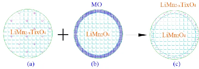
To reduce capacity fade, it is crucial to suppress Mn dissolution [9,13,18,19]. The two factors influencing Mn dissolution are the electrode material [20-22] and the electrolyte [23-25]. For the electrode material, maintaing bulk LMO, studies have focused mainly on modifications of LMO [26-28]. Elements, such as Al3+ [18,19], Ti4+ [20] and Ni2+ [29], have been extensively introduced as bulk dopants for LMO, and a modified structure is illustrated in Figure 1a. Bulk-doped LMO reduces the possibility of the Jahn-Teller effect during charge/discharge cycling and increases the stabilization of the crystal structure. These are beneficial to reduce capacity fade. Howerver, these modifications may also give rise to reduced specific capacity. Another popular way to suppress Mn dissolution is coating the LMO surface with a modified surface layer [22,26,27,30], as illustrated in Figure 1b. The surface-coating layer forms a physical barrier between the pristine material and the electrolyte, which can effectively prevent LMO from electrolyte corrosion. However, structure dissimilarity between the coating layer and spinel LMO is an issue that needs to be addressed, as the heterostructural interface will result in phase segregation or separation, and a high-resistant coating layer is prone to block ionic and electronic transport channels at the LMO surface, leading to a lower capacity, severe capacity fading, and a decreased rate capability. Recently, many efforts have attempted to improve the cycling performances of LIBs via surface-doping methods, i.e., modified layers possessing homogeneous structures with pristine LMO [28,31]. In this sense, the specific capacity and capacity fade are both considered and balanced [14,32]. The surface layer effectively prevents LMO from etching by the electrolyte, and meanwhile, the doped layer maintains the Li+ and electronic transport channels.
[image:3.596.138.460.152.264.2]
forms a physical barrier between LiMn2O4 and the electrolyte, which enhances the cathode resistance to corrosive attack from the electrolyte and effectively suppresses the dissolution of Mn, especially at elevated temperatures. The experiments at elevated temperature and high rate fully demonstrate the excellent properties of TiO2-modified LMO (TLMO) as a cathode active material.
Figure 1. Schematic illustration of the crystal structure of lithium manganate with (a) bulk doping, (b) surface coating, (c) surface doping, which combines the characteristics of bulk doping and surface coating (M represents the doping agent).
2. EXPERIMENTAL
2.1 Synthesis and characterization of LiMn2O4 and TiO2-modified LiMn2O4
Spinel LiMn2O4 particles were synthesized using a solid-state method. MnCO3 (Tianjin Fuchen, 99%) and Li2CO3 (Sigma-Aldrich, 99.0%) were mixed fully (Mn: Li molar ratio=2:1.05) and ground for 18 h at a rate of 500 r/min, and ethanol was added to continue grinding. The ground product was dried and calcinated at a temperature of 750 °C.
TiO2-modified spinel lithium manganate (TLMO) cathode active material with a core-shell structure was prepared according to following procedures. As-prepared LMO was modified with TiO2 using a sol-gel method. Tetrabutyl titanate (Sigma-Aldrich, 99%) was first dissolved in ethanol to make a 20% solution. Then the solution was dropped slowly into an acetic acid solution (composed of 10% acetic acid, 50% ethanol and 40% water) with agitation to obtain a colloid, and the colloid was further diluted to 5% by adding ethanol to prevent aggregation. Then, the prepared LiMn2O4 powder was added to the diluted colloid. After agitation for 20 min, the mixture was dried at 80 °C for 3 h and calcinated at 750 °C for 4 h.
Scanning electron microscopy (SEM) (Zeiss Merlin) combined with EDS was used to observe the surface morphologies and elemental compositions of pristine and modified LiMn2O4. X-ray diffraction (XRD) patterns (Bruker D8 Advance) were collected to determine the crystal phases of the materials.
2.2 Electrochemical tests
aluminum foil using a 200 m doctor blade. Lithium foil was used as an anode material, and a commercial electrolyte of 1 M LiPF6 dissolved in ethylene carbonate/dimethyl carbonate/ethylmethyl carbonate (EC/DMC/EMC, 1:1:1 in a volume ratio, Zhangjiagang Guotai-Huarong New Chemical Materials Co., Ltd) was used. Coin cells (2025) were assembled in an argon-filled glove box. Charge-discharge cycles were conducted at different C (calculated by an anticipated capacity of 148 mAh/g for Li2MnO4) using a lithium ion battery performance test system from Shenzhen Neware Technology Limited Corporation. The experiments were carried out galvanostatically between 3.0 V and 4.3 V at room temperature and at 55 °C.
2.3 Mn dissolution test
For Mn dissolution tests, the cathode quantity was controlled within 2.1~2.3 mg with active component of pristine LMO or TLMO occupying 80 wt%. After assembled as described in section 2.2, the cells were charged and discharged for 5 cycles at 0.1 C at 55 °C to form stable solid electrolyte interphase (SEI). Then the cells were disassembled and rinsed with DMC to remove residual electrolyte. After drying, the cathode material was placed into a centrifugal tube, and 1.5 mL electrolyte was added into the tube and sealed. The sealed centrifugal tube was heated at 55 °C. After several days, 1 mL of the supernatant fraction was taken out to conduct inductively coupled plasma optical emission spectrometry (Thermo Fisher ICAP 6000).
3. RESULTS AND DISCUSSION
3.1 Characterization of pristine and modified LiMn2O4
The SEM images of pristine LiMn2O4 and TiO2-modified LiMn2O4 are shown in Figure 2. The LiMn2O4 particles synthesized using a solid-state method are uniform and within 500 nm (Figure 2a). After modification (Figure 2b), the structure retains the perfect structure of LMO, indicating that the chemical treatment during the modification does not destroy the pristine structure and that the spinel structure of the LiMn2O4 core is preserved.
[image:5.596.71.530.72.398.2]
Figure 2. SEM images of (a) pristine LiMn2O4 and (b) TiO2-modifed LiMn2O4; EDS spectra of (c) pristine LiMn2O4 and (d) TiO2-modified LiMn2O4.
[image:5.596.135.463.470.729.2]
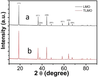
Figure 3 compares the XRD patterns of unmodified spinel LMO and surface-doped TLMO. Both samples have representative index facets of the (111), (311) and (440) diffractions, which are consistent with the standard spectrum [6,33,34]. In addition, no additional peaks for other phases are observed. This means the normal spinel structure is preserved after modification [34]. The data clearly demonstrate that the shell layer retains the spinel structure of the core, which would be helpful to stabilize lithium ion transport. In addition, refined XRD patterns indicate that compared with pristine LMO, the positions of two peaks between 36 and 40 for TLMO changes slightly. The changes can be attributed to shell formation of solid spinel compound of LiTixMn2-xO4 on the core of spinel LiMn2O4 [20] and diffusion of Ti4+ ions into the spinel lattice by replacing partial manganese ions [31].
3.2 Electrochemical performance at room temperature
[image:6.596.117.482.433.702.2]The capacity cyclabilities of LIBs at room temperature at a rate of 1 C using lithium as an anode and LMO or TLMO as a cathode were obtained, as shown in Figure 4. Each cell was first cycled with 0.1 C for 5 cycles to form an SEI. Following that, the cells were cycled at a constant current of 1 C. The discharge capacity of modified TLMO is larger than that of the unmodified cathode, and the electrochemical cycling performances of the two are almost the same [35]. The results show that there are enough ionic and electronic transport channels after modification [31], and the doped layer does not block Li+ transport. Also, it can be inferred that the structure is stable during cycling at room temperature.
3.3 Electrochemistry at elevated temperature
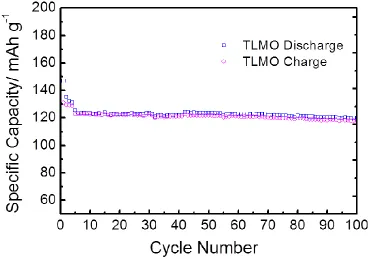
[image:7.596.114.486.327.586.2]It is well known that the poor charge/discharge cyclability of an LMO-based cathode material at elevated operating temperature hinders its wide application in commercial LIBs [6,36,37]. Figure 5 shows the capacity cyclability of TLMO at 55 °C with a charge/discharge rate of 1 C. Even at elevated temperature of 55 °C, the cell with the TLMO cathode material demonstrates excellent cycling stability, and the capacity is close to the theoretical value of an LMO-based material reported in the literature [21]. The results show that the core-shell structured cathode material suppresses Mn dissolution effectively and is stable during cycling. Even though the disproportionation reaction of Mn(III) in acid electrolyte may be accelerated by the increased HF generation at elevated temperature [13, 38], but the protective layer blocks the contact between LMO and the electrolyte, manganese is not easy to dissolve and spinel structure is preserved. In addition, at a rate of 1 C, the specific capacity at 55 °C (Figure 5) is higher than that at room temperature (Figure 4b), indicating the Li+ transport rate is increased at higher temperature.
Figure 5. Charge-discharge curves at 55 °C at a rate of 1 C for the TLMO cathode versus a Li anode between 3.0 V and 4.3 V.
3.4 High charge/discharge rates
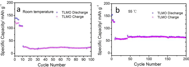
Then, the cells were cycled at a constant current of 10 C. From the data illustrated in Figure 6, Both at room temperature (Figure 6a) and at elevated temperature (Figure 6b), good cycling stability is demonstrated for the TLMO-based LIBs, which further proves the stability of the cathode material after modification. Furthermore, comparing the data in Figure 4b and Figure 6a, when the rate is increased, the capacity decreased dramatically, and the same conclusion can also be drawn from the data at 55 °C in Figure 5 and Figure 6b. The results imply that, at high rate, the charging time is short, the Li+ transport channels are limited and the amount of Li+ intercalation into the anode is far from the maximum capacity [40]. Meanwhile, the capacity at 55 °C is higher than that at room temperature. The results indicate that an elevated temperature does not accelerate Mn dissolution compared with the increased transport rate of Li+ for the core-shell structured spinel cathode, which demonstrates the excellent performance of the material.
[image:8.596.117.478.355.483.2]The excellent electrochemical performance of TiO2-modified LMO can be attributed to the effective suppression of Mn dissolution through the formation of the surface-doped structured TLMO, and the effect of Mn dissolution on SEI evolution is minimized, which can be analysed and verified from Mn dissolution experiments.
Figure 6. Charge-discharge curves at a rate of 10 C at (a) room temperature and (b) 55 °C for TiO2-LiMn2O4 versus a Li anode between 3.0 V and 4.3 V. Both cells were first cycled at 0.1 C for 5 cycles and then 1 C for another 5 cycles to form stable SEI.
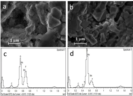
3.5 SEM and EDS characterization of the cathode material after cycling
[image:9.596.75.528.156.482.2]
subsequent disproportionation reaction catalyzed by HF in the electrolyte [7]. However, after modification, modified layer serves as physical barrier to block direct contact between spinel core and the electrolyte, thus manganese dissolution is effectively suppressed, and the structure retains perfect spinel state.
Figure 7. SEM images of (a) unmodified and (b) modified LMO cathodes after cycling at 10 C at 55 °C. EDS spectra for (c) pristine LiMn2O4 and (d) TiO2 modified LiMn2O4 after charge-discharge cycling at 10 C at 55 °C.
3.6 Mn dissolution in the electrolyte at elevated temperature
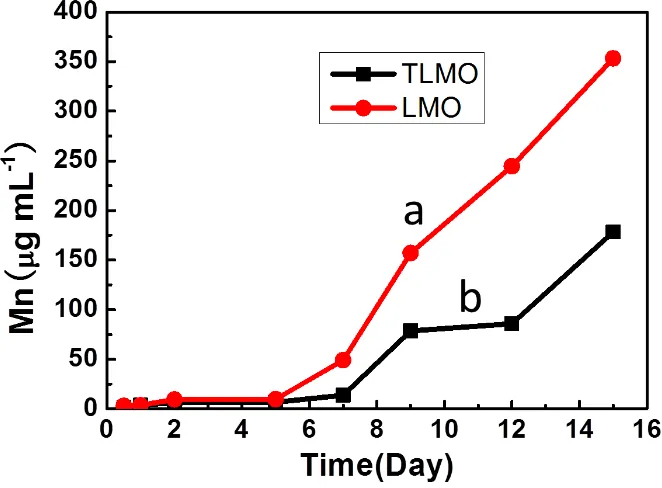
[image:10.596.133.464.343.587.2]Mn dissolution at elevated temperature was tested to correlate the relationship between the cathode material and Mn dissolution. After stable SEI layer was formed at 55 °C, the cathodes with unmodified and modified LMO were soaked in electrolyte at 55 °C, and inductively coupled plasma-AES was applied to analyse the concentrations of Mn2+ dissolved in the electrolyte. Figure 8 shows the correlation between the Mn2+ concentration and soaking time in the electrolyte at 55 °C. It shows that, before the fifth day, the Mn2+ concentration in the TiO2-modified cathode cell is almost the same with that in unmodified cathode cell. However, after the fifth day, the Mn2+ concentration for the TLMO-based cell is much lower than that for the LMO-TLMO-based cell. The data shows that manganese dissolution will occur both at LMO and TLMO cathodes, and the amount of manganese dissolution increases with longer soaking time. Meanwhile, after modification, the Mn2+ concentration is obviously decreased for TLMO cathode compared with that for LMO cathode. This strongly evidences that the formation of surface-doped layer of LiMn2-xTixO4 effectively suppresses the dissolution of manganese, thus improving the stability of the cathode.
Figure 8. Correlation between the Mn concentration at the LMO (a) and TLMO (b) cathode after SEI formation and soaking time in the electrolyte at elevated temperature of 55 °C.
4. CONCLUSIONS
Furthermore, the homogeneous structures between the doped layer and pristine LiMn2O4 reduced the possibility of phase segregation or separation. Moreover, the LiMn2-xTixO4 shell layer retained the ionic and electronic transport channels, which was very important to stabilize the capacity. Even at a high discharging rate of 10 C, the TiO2-modified LiMn2O4-based LIBs exhibited good performance. This study suggests that the surface-doping method with structural similarity is encouraging to improve battery cycle performance with LiMn2O4 cathodes and is promising for application in other Mn-based cathodes.
ACKNOWLEGEMENTS
This work was supported by the Natural Science Foundation of China (Nos. 21561016 and 21661015), the Natural Science Foundation of the JiangXi Province of China (No. 20161BBE50052) and the Natural Science Foundation from Department of Education of the JiangXi Province (GJJ150775).
References
1. K. Xu. Chem. Rev., 104 (2004) 4303. 2. K. Xu. Chem. Rev., 114 (2014) 11503.
3. J. Y. Luo, X. L. Li and Y. Y. Xia. Electrochim. Acta, 52 (2007) 4525. 4. M. Armand and J. M. Tarascon. Nature, 451 (2008) 652.
5. L. Yang, M. Takahashi and B. F. Wang. Electrochim. Acta, 51 (2006) 3228. 6. X. F. Li and Y. L. Xu. Appl. Surf. Sci., 253 (2007) 8592.
7. J. Cho and M. M. Thackeray. J. Electrochem. Soc., 146 (1999) 3577.
8. C. Zhan, J. Lu, A. Jeremy Kropf, T. Wu, A. N. Jansen, Y.-K. Sun, X. Qiu and K. Amine. Nat. Commun., 4 (2013) 3437.
9. H. Shin, J. Park, A. M. Sastry and W. Lu. J. Power Sources, 284 (2015) 416. 10. W. Choi and A. Manthiram. J. Electrochem. Soc., 153 (2006) A1760.
11. H. H. Zheng, Q. N. Sun, G. Liu, X. Y. Song and V. S. Battaglia. J. Power Sources, 207 (2012) 134. 12. H. H. Zheng, L. Zhang, G. Liu, X. Y. Song and V. S. Battaglia. J. Power Sources, 217 (2012) 530. 13. N. P. W. Pieczonka, Z. Y. Liu, P. Lu, K. L. Olson, J. Moote, B. R. Powell and J. H. Kim. J. Phys.
Chem. C, 117 (2013) 15947.
14. F. H. Zheng, C. H. Yang, X. H. Xiong, J. W. Xiong, R. Z. Hu, Y. Chen and M. L. Liu. Angew. Chem. Int. Ed., 54 (2015) 13058.
15. D. P. Abraham, T. Spila, M. M. Furczon and E. Sammann. Electrochem. Solid-State Lett., 11 (2008) A226.
16. C. G. Han, C. Y. Zhu, G. Saito and T. Akiyama. Electrochim. Acta, 209 (2016) 225.
17. M. Hirayama, H. Ido, K. Kim, W. Cho, K. Tamura, J. Mizuki and R. Kanno. J. Am. Chem. Soc., 132 (2010) 15268.
18. D. Song, H. Ikuta, T. Uchida and M. Wakihara. Solid State Ionics, 117 (1999) 151. 19. A. Yuan, L. Tian, W. Xu and Y. Wang. J. Power Sources, 195 (2010) 5032. 20. L. Yu, X. Qiu, J. Xi, W. Zhu and L. Chen. Electrochim. Acta, 51 (2006) 6406.
21. X. H. Tan, H. Q. Liu, Y. Jiang, G. Y. Liu, Y. J. Guo, H. F. Wang, L. F. Sun and W. G. Chu. J. Power Sources, 328 (2016) 345.
22. G. H. Waller, P. D. Brooke, B. H. Rainwater, S. Y. Lai, R. Hu, Y. Ding, F. M. Alamgir, K. H. Sandhage and M. L. Liu. J. Power Sources, 306 (2016) 162.
23. S. Komaba, N. Kumagai and Y. Kataoka. Electrochim. Acta, 47 (2002) 1229.
24. X. Y. Hu, C. L. Chen, J. W. Yan and B. W. Mao. J. Power Sources, 293 (2015) 187.
26. D. Liu, X. Liu and Z. He. J. Alloy Compd., 436 (2007) 387.
27. B. Li, J. Wang, Z. L. Cao, P. Zhang and J. B. Zhao. J. Power Sources, 325 (2016) 84.
28. C.-G. Han, C. Zhu, G. Saito, N. Sheng, T. Nomura and T. Akiyama. Electrochim. Acta, 224 (2017) 71.
29. H. M. Wu, J. P. Tu, X. T. Chen, Y. Li, X. B. Zhao and G. S. Cao. J. Solid State Electr., 11 (2007) 173.
30. J. S. Kim, C. S. Johnson, J. T. Vaughey, S. A. Hackney, K. A. Walz, W. A. Zeltner, M. A. Anderson and M. M. Thackeray. J. Electrochem. Soc., 151 (2004) A1755.
31. J. Lu, C. Zhan, T. Wu, J. Wen, Y. Lei, A. J. Kropf, H. Wu, D. J. Miller, J. W. Elam, Y.-K. Sun, X. Qiu and K. Amine. Nat. Commun., 5 (2014) 5693.
32. H. R. Lee, H. R. Seo, B. Lee, B. W. Cho, K.-Y. Lee and S. H. Oh. Appl. Surf. Sci., 392 (2017) 448. 33. T. Eriksson, T. Gustafsson and J. O. Thomas. Electrochem. Solid-State Lett., 5 (2002) A35.
34. S. Zhao, Y. Bai, Q. Chang, Y. Yang and W. Zhang. Electrochim. Acta., 108 (2013) 727.
35. J. M. Lim, R. G. Oh, D. Kim, W. Cho, K. Cho, M. Cho and M. S. Park. Chemsuschem., 9 (2016) 2967.
36. C. H. Lu and S. W. Lin. J. Mater. Res., 17 (2002) 1476.
37. J. S. Gnanaraj, V. G. Pol, A. Gedanken and D. Aurbach. Electrochem. Commun., 5 (2003) 940. 38. J. H. Kim, N. P. W. Pieczonka, Z. Li, Y. Wu, S. Harris and B. R. Powell. Electrochim. Acta., 90
(2013) 556.
39. Y. Yang, B. Qiao, X. Yang, L. Fang, C. Pan, W. Song, H. Hou and X. Ji. Adv. Funct. Mater., 24 (2014) 4349.
40. F. Wu, N. Li, Y. Su, H. Shou, L. Bao, W. Yang, L. Zhang, R. An and S. Chen. Adv. Mater., 25 (2013) 3722.