This is a repository copy of Mechanical performance of steel fibre reinforced rubberised concrete for flexible concrete pavements.
White Rose Research Online URL for this paper: http://eprints.whiterose.ac.uk/135501/
Version: Accepted Version
Article:
Alsaif, A, Koutas, L, Bernal, SA et al. (2 more authors) (2018) Mechanical performance of steel fibre reinforced rubberised concrete for flexible concrete pavements. Construction and Building Materials, 172. pp. 533-543. ISSN 0950-0618
https://doi.org/10.1016/j.conbuildmat.2018.04.010
© 2018 Elsevier Ltd. This manuscript version is made available under the CC-BY-NC-ND 4.0 license http://creativecommons.org/licenses/by-nc-nd/4.0/.
eprints@whiterose.ac.uk https://eprints.whiterose.ac.uk/
Reuse
This article is distributed under the terms of the Creative Commons Attribution-NonCommercial-NoDerivs (CC BY-NC-ND) licence. This licence only allows you to download this work and share it with others as long as you credit the authors, but you can’t change the article in any way or use it commercially. More
information and the full terms of the licence here: https://creativecommons.org/licenses/
Takedown
If you consider content in White Rose Research Online to be in breach of UK law, please notify us by
Mechanical Performance of Steel Fibre Reinforced Rubberised
1Concrete for Flexible Concrete Pavements
23
Abdulaziz Alsaif,a*, Lampros Koutasa , Susan A. Bernala, Maurizio Guadagninia
4
Kypros Pilakoutasa 5
Department of Civil and Structural Engineering, The University of Sheffield, Sir Frederick Mappin
6
Building, Mappin Street, Sheffield, S1 3JD, UK.
7 8
* Corresponding author: email: asaalsaif1@sheffield.ac.uk; Tel: + 44 (0) 114 222 5729,
9
Fax: + 44 (0) 114 2225700
10 11
Abstract
12This work aims to develop materials for flexible concrete pavements as an alternative to asphalt 13
concrete or polymer-bound rubber surfaces and presents a study on steel fibre reinforced 14
rubberised concrete (SFRRuC). The main objective of this study is to investigate the effect of 15
steel fibres (manufactured and/or recycled fibres) on the fresh and mechanical properties of 16
rubberised concrete (RuC) comprising waste tyre rubber (WTR). Free shrinkage is also 17
examined. The main parameters investigated through ten different mixes are WTR and fibre 18
contents. The results show that the addition of fibres in RuC mixes with WTR replacement 19
substantially mitigates the loss in flexural strength due to the rubber content (from 50% to 9.6% 20
loss, compared to conventional concrete). The use of fibres in RuC can also enable the 21
development of sufficient flexural strength and enhance strain capacity and post-peak energy 22
absorption behaviour, thus making SFRRuC an ideal alternative construction material for flexible 23
pavements. 24
Keywords: Recycled fibres; Rubberised concrete; Steel fibre concrete; Rubberised steel fibre 25
2
1. Introduction and Background
27
Road pavements and slabs on grade are constructed either with flexible asphalt or rigid concrete. 28
Flexible pavements can better accommodate local deformations, but lack the durability of 29
concrete which is by nature much stiffer. A flexible concrete pavement could combine the 30
advantages of both types of pavements, however, requires a radical change in how it is 31
constructed. Rubberised concrete which can be design to have stiffness values similar to that of 32
asphalt, can be used as an alternative construction material for flexible pavements. It is well 33
known, however, that the use of rubber in substantial enough quantities can also adversely affect 34
all of the other mechanical properties of Portland-based concrete. Furthermore, virgin rubber 35
aggregates are significantly more expensive than natural aggregates. To address these issues, this 36
study aims to use recycled materials derived from waste tyre rubber (WTR) not only to provide 37
economically and structurally sound alternatives, but also to enable the development of a 38
sustainable flexible concrete pavement solution. 39
40
1.1 Waste tyre materials
41
According to The European Tyre Recycling Association [1], approximately 1.5 billion tyres are 42
produced worldwide each year and a quarter of this amount is arisen in EU countries. It is also 43
estimated that for every tyre brought to the market, another tyre reaches its service life and 44
becomes waste. The European Directive 1991/31/EC [2] introduced a set of strict regulations to 45
prevent the disposal of waste tyres in landfills as a means of preventing environmental pollution 46
and mitigating health and fire hazard [3-5]. As a result, in the EU any type of waste tyre disposal 47
in the natural environment has been banned since 2006. The European Directive 2008/98/EC [6] 48
has also established a disposal hierarchy leading to a serious effort for effective waste tyre 49
3 Typical car or truck tyres comprise 75-90% rubber, 5-15% high-strength corded steel wire and 51
5-20% polymer textile. WTR is currently used as fuel, in particular in cement kilns. It is also used 52
in applications, such as synthetic turf fields, artificial reefs, sound proof panels, playground 53
surfaces and protective lining systems for underground infrastructure [7, 8]. While these 54
applications make a positive contribution to recycling WTR, demand with respect to the volume 55
of waste tyres is still small. Since cement-based materials constitute the largest portion of 56
construction materials worldwide, recycling WTR in concrete is a positive way to respond to the 57
environmental challenge and to the significant redundant volumes of waste materials. 58
59
1.2 Rubberised concrete
60
In the past two decades, several studies have investigated the addition of WTR in concrete, but 61
only recently for structural applications [9-12]. Concretes containing rubber particles present high 62
ductility and strain capacity, increased toughness and energy dissipation [11, 13, 14]. These 63
properties, along with the material’s high impact and skid resistance, sound absorption, thermal 64
and electrical insulation [5, 15-17] make rubberised concretes (RuC) a very attractive building 65
material for non-structural applications. 66
67
Despite the good mechanical properties of rubber, production of RuC has several important 68
drawbacks: (a) reduction in workability associated with the surface texture of the rubber particles 69
[3, 11, 18, 19], (b) increased air content as the rough and non-polar surface of rubber particles 70
tend to repel water and increase the amount of entrapped air [20-22], and (c) reduction in the 71
compressive strength (up to approximately 90% reduction with 100% replacement of natural 72
aggregates), tensile strength and stiffness [11, 23]. The reduction in mechanical properties is 73
4 to the other materials in the mixture, and the weak bond between cement paste and rubber 75
particles [21, 24, 25]. One of the potential alternatives to enhance the mechanical performance of 76
RuC is the addition of fibres. 77
78
1.3 Steel fibre reinforced concrete using recycled fibres
79
The steel cord used as tyre reinforcement is a very high strength cord of fine wires (0.1- 0.3 mm). 80
The same cord is currently being used in limited volumes to reinforce concrete in high value 81
security applications, such as vaults and safe rooms. At the same time when extracted from tyres, 82
the cord is either discarded or at best re-melted. Commercially available steel fibre reinforcement 83
for concrete comprises thin fibres with a diameter ranging from 0.3 to 1 mm and has a sizable 84
market mainly in tunnel and slabs on grade applications. Hence, it is natural to consider tyre wire 85
for concrete applications [26], as using recycled tyre steel fibres (RTSF) from waste tyres, instead 86
of manufactured steel fibres (MSF), can reduce costs and positively contribute to sustainability 87
by reducing the emissions of CO2 generated from manufacturing steel fibres [27, 28]. Recently,
88
many studies have examined the use of recycled steel fibres in concrete [27, 29-32]. By assessing 89
mechanical properties, most of these studies confirm the ability of classified RTSF to reinforce 90
concrete. 91
92
1.4 Steel fibre reinforced rubberised concrete
93
Despite the fact that there are many studies on RuC and SFRC, there are very few studies 94
examining the effect of using steel fibres and rubber particles together in concrete, and most of 95
these focus on cement-based mortars or self-compacted concrete (SCC) [33-37]. Turatsinze et al. 96
[33] investigated the synergistic effect of MSF and rubber particles, in particular replacing sand 97
5 cracking behaviour, while the addition of rubber (up to 30% by volume of sand) significantly 99
increased the deflection at peak load. Ganesan et al. [35] studied the influence of incorporating 100
crumb rubber and MSF in SCC. Compared to conventional SCC, they reported a 35% increase 101
in flexural strength when 15% of sand (by volume) was replaced with crumb rubber and 0.75% 102
(by volume) fraction of steel fibres was added. Xie et al. [36] conducted an experimental study 103
on the compressive and flexural behaviour of MSF reinforced recycled aggregate concrete with 104
crumb rubber. They found that as the amount of rubber content was increased, the reduction in 105
the compressive strength was smaller compared to other studies, and they attributed this 106
behaviour to the inclusion of steel fibres. They also concluded that steel fibres played a significant 107
role in enhancing the residual flexural strength, which was slightly affected by the increase in 108
rubber content. Finally, Medina et al. [37] examined the mechanical properties of concrete 109
incorporating crumb rubber and steel or plastic fibres coated with rubber. They observed that 110
concrete with rubber and fibres presents better compressive and flexural behaviour as well as 111
impact energy absorption than plain rubberised concrete. 112
113
To the best of the authors' knowledge only limited information is available on the mechanical 114
behaviour of steel fibre reinforced rubberised concrete (SFRRuC) where both fine and coarse 115
aggregates are replaced with rubber particles in significant volumes (exceeding 20% by volume 116
of total aggregates) and further studies are needed to understand its performance where much 117
larger rubber volumes are used. Large volumes of rubber are necessary to achieve more flexible 118
concrete pavements. In addition, the behaviour of SFRRuC in which RTSF are used alone or in 119
a blend with MSF, has not been studied yet. 120
6 This study investigates the fresh properties as well as the compressive and flexural behaviour of 122
several SFRRuC mixes with the aim of developing optimized mixes suitable for pavement 123
applications. Coarse and fine aggregates are partially replaced by different sizes and percentages 124
of tyre rubber particles and various dosages and blends of steel fibres, MSF and/or RTSF, are 125
used as fibre reinforcement. Details of the experimental programme and the main experimental 126
results are presented and discussed in the following sections. This study contributes to the 127
objectives of the EU-funded collaborative project Anagennisi (http://www.anagennisi.org/) that 128
aims to develop innovative solutions to reuse all waste tyre components. 129
130
2. Experimental Programme
1312.1 Parameters under investigation
132
The parameters assessed in this study were: (i) the rubber content used as partial replacement of 133
both fine and coarse aggregates (0%, 20%, 40% or 60% replacement by volume), and (ii) steel 134
fibre content (0 or 20 kg/m3 MSF + 20 kg/m3 RTSF, or 40 kg/m3 RTSF). A total of 10 different
135
mixes were prepared. For each mix, three cubes (150 size), three cylinders (100 mm-136
diameter and 200 mm-length), and three prisms (100x100 mm-cross section and 500 mm-length) 137
were cast. The cubes and cylinders were used to obtain the uniaxial compressive strength and the 138
compressive stress-strain curve, respectively, whereas the prisms were cured in different 139
conditions to evaluate free shrinkage strain (autogenous and drying) and then subjected to three-140
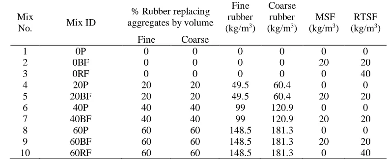
point bending. Table 1 summarises the different mix characteristics and the ID assigned to the 141
mixes. The mix ID follows the format NX, where N denotes the amount of rubber content used 142
as partial replacement of both fine and coarse aggregates (0, 20, 40 or 60%), while X represents 143
the type of steel fibre reinforcement and can be either P, BF or RF (Plain, Blend of Fibres or 144
7 60% of rubber particles as conventional aggregate replacement and consists of blend fibres (20 146
kg/m3 MSF and 20 kg/m3 RTSF).
147
[image:8.612.107.502.175.338.2]148
Table 1. Concrete mix ID, and quantities of rubber and steel fibres added in each mix 149
Mix
No. Mix ID
% Rubber replacing aggregates by volume
Fine rubber
(kg/m3)
Coarse rubber
(kg/m3)
MSF
(kg/m3)
RTSF
(kg/m3)
Fine Coarse
1 0P 0 0 0 0 0 0
2 0BF 0 0 0 0 20 20
3 0RF 0 0 0 0 0 40
4 20P 20 20 49.5 60.4 0 0
5 20BF 20 20 49.5 60.4 20 20
6 40P 40 40 99 120.9 0 0
7 40BF 40 40 99 120.9 20 20
8 60P 60 60 148.5 181.3 0 0
9 60BF 60 60 148.5 181.3 20 20
10 60RF 60 60 148.5 181.3 0 40
150
151
2.2 Materials and mix preparation
152
2.2.1 Materials
153
2.2.1.1 Rubberised concrete
154
A high strength commercial Portland Lime Cement CEM II-52.5 N containing around 10–15% 155
Limestone in compliance with BS EN 197-1 [38] was used as binder. The coarse aggregates used 156
comprised natural round river washed gravel with particle sizes of 5-10 mm and 10-20 mm 157
[specific gravity (SG)=2.65, absorption (A) =1.2%]. The fine aggregates used comprised medium 158
grade river washed sand with particle sizes of 0-5 mm (SG=2.65, A=0.5%). Pulverised fuel ash 159
(PFA) and silica fume (SF) were used as partial replacement of cement (10% by weight for each) 160
to enhance the fresh and mechanical properties of the mixes. Plasticiser and superplasticiser were 161
also added to improve cohesion and mechanical properties (mix details are given in Section 162
8 The rubber particles used in this study were recovered through the shredding process of waste 164
[image:9.612.42.545.39.652.2]tyres at ambient temperature and where obtained from two different sources. As depicted in 165
Figure 1a, the fine rubber particles were provided in the ranges of 0-0.5 mm, 0.5-0.8 mm, 1-2.5 166
mm and 2-4 mm and were used in the concrete mix in the ratio 12:12:32:44 of the total added 167
fine rubber content, while the course rubber particles were supplied in the ranges of 4-10 mm and 168
10-20 mm and were utilized in the concrete mix in the ratio 50:50 of the total added course rubber 169
content. Figure 2 presents the particle size distribution of the natural aggregates (NA) and rubber 170
particles used, obtained according to ASTM-C136 [39]. To limit the influence of rubber size on 171
concrete particle packing, conventional aggregates were replaced with rubber particles of roughly 172
similar size distribution to minimise the impact on the packing of the concrete mix constituents. 173
A relative density of 0.8 was used to calculate the mass of rubber replacing natural aggregates, 174
as determined using a large rubber sample that was accurately cut and measured. 175
176
177
178
Figure. 1 a)Rubber particles, b) MSF and RTSF used in this study and c) length distribution 179
analysis of RTSF 180
a)
[image:9.612.77.543.428.607.2]9 181
[image:10.612.141.483.65.325.2]182
Figure. 2 Particle size distribution for conventional aggregates and rubber 183
184
Table 2 reports the physical properties of the coarse aggregates (5-20 mm) and the coarse rubber 185
particles (4-20 mm), obtained through a series of tests: (a) particle density and water absorption 186
according to EN 1097-6 [40], (b) loose bulk density according to EN 1097-3 [41], and (c) particle 187
shape-flakiness index according to EN 933-3 [42]. The physical properties of the fine aggregates 188
and fine rubber particles were not evaluated due to difficulties in performing the tests on fine 189
rubber particles as they floated when submerged in water. 190
191
As it was not possible to complete the flakiness tests for all particle sizes, in the end this 192
information was not used directly in the mix design. It should be noted though that the higher 193
flakiness influenced the optimisation of the mix design and more fines and supplementary 194
materials were necessary, as reported in [11]. 195
196
0 5 10 15 20 25
0 20 40 60 80 100
Cumu
lative
pe
rce
nt
pa
ssing
(%)
Particle size (mm)
10 Table 2. Physical properties of coarse aggregates and coarse rubber particles
197
198
199
200
201
202
203
204
2.2.1.2 Steel Fibres
205
The MSF were crimped type steel fibres with a length of 55 mm, diameter of 0.8 mm and tensile 206
strength of 1100 MPa. The RTSF were cleaned and screened fibres (typically containing < 2% 207
of residual rubber) and had lengths in the range of 15-45 mm (at least 60% by mass), diameters 208
<0.3 mm and tensile strength of 2000 MPa. Figure 1b presents both types of fibres (MSF and 209
RTSF) used in this study and Figure 1c illustrates the length distribution of the RTSF based on a 210
digital optical correlation method that combines photogrammetry and advanced pattern 211
recognition to determine the length of individual fibre from high speed image of free falling 212
dispersed fibres [43]. 213
214
2.2.2 Mix design
215
The mix design used in this experimental study (adopted from Raffoul et al. [11]) was optimised 216
to be used for typical concrete bridge piers targeting a compressive strength of 60 MPa (cylinder), 217
and suited the replacement of 0%, 20%, 40% and 60% of WTR without excessive degradation in 218
fresh and mechanical properties. The optimised mix proportions for 0% rubber content 219
(conventional concrete), are shown in Table 3. 220
Physical properties/Type of rubber
Rubber - Source 1 4-10 mm
Rubber -Source 2 10-20 mm
Natural aggregates
5-10 mm
Natural aggregates 10-20 mm
Apparent particle density, kg/m3 1136 1103 2685 2685
Oven-dried density, kg/m3 1032 1090 2599 2599
Saturated and surface-dried
particle density, kg/m3 1123 1101 2631 2631
Water absorption after 24h, % 5.3-8.8 0.8-1.3 1.2 1.2
Bulk specific gravity 1.1 1.1 2.6 2.6
Bulk density, kg/m3 454 485 1511 1583
11 Table 3. Concrete mix proportions (without rubber content)
221
Material Quantity
CEM II – 52.5 MPa 340 kg/m3
Silica fume (SF) 42.5 kg/m3
Pulverised fuel ash (PFA) 42.5 kg/m3
Natural fine aggregates 0-5 mm 820 kg/m3
Natural coarse aggregates 5-10 mm 364 kg/m3
Natural coarse aggregates 10-20 mm 637 kg/m3
Water 150 l/m3
Plasticiser 2.5 l/m3*
Superplasticiser 5.1 l/m3
*It was increased at higher amounts of rubber and fibres were added to the concrete (2.5-4.75 l/m3)
222
223
2.2.3 Mixing, casting and curing procedure
224
A 200 litre pan mixer was used for all mixes. The procedure used for mixing the concrete started 225
with conventional aggregates dry mixed for 30 seconds together with the rubber particles. 226
Subsequently, half of the total amount of water was added and mixed for about 1 minute. The 227
mix was allowed to rest for 3 minutes allowing the conventional aggregates to get saturated. After 228
that, the cementitious materials (Portland cement, silica fume and fly ash) were added, followed 229
by the remaining water and the chemical admixtures. The fresh concrete was finally mixed for 230
another 3 minutes. For those concrete mixes with steel fibres, fibres were manually integrated 231
into the concrete during mixing at the last mixing stage. 232
233
The concrete fresh properties, including slump, air content and fresh density, were then assessed 234
for each mix according to the standardised methods described in EN 12350 2 [44], EN 12350 7 235
[45], and EN 12350 6 [46], respectively. The concrete specimens were cast in plastic cube (150 236
mm) and cylinder moulds (100x200 mm), and prismatic steel moulds (100x100x500 mm) 237
12 vibrated (25s per layer) on a vibrating table. After casting, specimens were covered with plastic 239
sheets to prevent moisture loss, and left under standard laboratory conditions for 48h until 240
demoulding. The specimens were then kept in a mist room (21 C 2 and 95 5% relative 241
humidity (RH)) for 28 days, except for the prisms used for shrinkage measurements that were left 242
in the mist room for 7 days and then stored in a control room (24 C 2 and 42 5 RH) for 50 243
days. After the curing period, the specimens were kept under standard laboratory conditions (20 244
C 2 and 50 5 RH) until testing.
245
246
3. Test set-up and procedure
2473.1 Compression testing
248
Prior to testing, the top faces of the cylinders were cut and ground according to EN 12390-3 [49]. 249
For the RuC cylinders, extra measures were taken to prevent local failure during testing by 250
confining their two ends with high-ductility post-tensioned straps, as proposed by Garcia et al. 251
[50]. Axial compression tests were performed on concrete cubes and cylinders according to EN 252
12390 3 [49] under monotonic loading until failure. For all tested cylinders, the compression tests 253
were performed using a servo-hydraulic universal testing machine with a load capacity of 1000 254
kN. The load was applied on the cylinders at a displacement rate of 0.3 mm/min. The local axial 255
strain was measured using two diagonally opposite strain gauges at mid-height. The global axial 256
strain was measured using three laser sensors, with an accuracy of 40µ , placed radially around 257
the specimens (120o apart) using two metallic rings. The metallic rings were attached to the 258
specimens using four clamp screws, covering the middle zone of the cylinder and resulting in 100 259
mm gauge length. The tests on cubes were carried out using a standard compression machine 260
13
3.2 Three-point bending tests
262
The flexural behaviour of the concrete specimens was assessed by performing three-point 263
bending tests using an electromagnetic universal testing machine with a load capacity of 300 kN. 264
A detailed schematic of the test setup is provided in Figure 3. The loading point allowed for both 265
the in-plane and out-of-plane rotation of the prism. Two LVDTs were mounted at the middle of 266
a yoke (one on each side) as suggested by the JCI [51] to measure the net deflection at mid-span. 267
[image:14.612.87.529.239.431.2]268
Figure. 3 Schematic representation of the flexural test set-up 269
270
A clip gauge of 12.5 mm-length was fixed at the middle of the bottom side of the prism, where a 271
5 mm-wide and 15 mm-deep notch had been sawn. The clip gauge measurement (crack mouth 272
opening displacement -CMOD) was used to control the loading rate as suggested by RILEM [52]. 273
All tests were performed under a rate of 50 m/min for CMOD ranging from 0 to 0.1 mm, 200 274
m/min for CMOD ranging from 0.1 to 4 mm, and 8000 m/min for CMOD higher than 4 mm. 275
276
3.3 Free-shrinkage
277
The autogenous and drying shrinkage tests were performed according to EN-126174 [53]. 278
14 specimens was increased from 40x40x160 mm (as suggested by the standard) to 100x100x500 280
mm. Specimens were demoulded two days after casting and fitted with steel “Demec” points 281
(locating discs) using plastic padding. Two Demec points were fixed 300 mm apart on each of 282
the vertical (as cast) sides of the prism. 283
284
The first strain measurement was recorded after 30 minutes to allow for the hardening of the 285
adhesive. For autogenous shrinkage, the specimens were kept in a mist room with controlled 286
temperature and humidity conditions (21 oC 2 and 95 5% RH) and measurements were taken 287
at the ages of 1, 2, 3 and 7 days after demoulding. For drying shrinkage, specimens were stored 288
in a chamber with controlled temperature and humidity conditions (24 oC 2 and 40 5 RH)
289
and measurements were taken at the ages of 10, 14, and 28 and 56 days after demoulding. 290
291
4. Experimental Results and Discussion
2924.1 Fresh state properties
293
4.1.1 Workability
294
To assess the workability of rubberised concrete, most researchers (including the authors of this 295
paper) use the slump test which appears to be a consistent and easy-to-apply method in practice 296
[3, 7, 10, 11, 19]. Table 4 shows the slump results of all mixes as well as their corresponding 297
slump classes, all of which fulfil the consistency requirements as described in pavement design 298
standard BS EN 13877-1[54] and the normative reference BS EN 206-1 [55] either for fixed-299
form or slip-form (class S1) paving . The desired slump class was targeted to be at least S3 (slump 300
≥ 90 mm), by modifying the plasticiser dosage which was increased proportionally to the amount 301
15 workability for mixes 60BF and 60RF was quite low (40 and 35 mm, respectively) although high 303
amounts of plasticiser and superplasticiser were added (4 per m3 and 5.1 per m3 of concrete,
304
respectively). Nevertheless, this low workability did not raise any issues during handling, placing 305
or finishing of the mixes due to the high rubber dosage (60%). No signs of segregation, bleeding 306
or excessive “balling” were observed in any of the mixes. 307
[image:16.612.74.542.257.464.2]308
Table 4. Fresh concrete properties for all concrete mixes 309
310
The results show that slump decreases with the addition of steel fibres, and further decreases with 311
the inclusion of rubber, even though the amount of plasticiser was increased proportionally. By 312
comparing the slump values of the control mix with the SFRC mixes without rubber (0BF and 313
0RF), it can be seen that fibres caused a slump drop of 18.8% for both SFRC mixes. This decrease 314
may be caused by increased friction between the RTSF, which have a large specific surface area, 315
and the concrete constituents during mixing. Additionally, the tendency of steel fibres to 316
agglomerate also has an adverse effect on workability. 317
318
Mix
No. Mix ID
Extra plasticiser added
L/m3
Slump (mm)
Slump class
Air content
%
Bulk density
(kg/m3)
Theoretical density
(kg/m3)
1 0P 0 240 S5 1.35 2406 2426
2 0BF 0 195 S4 1.5 2452 2454
3 0RF 0 195 S4 1.15 2447 2454
4 20P 0.25 200 S4 1.9 2258 2211
5 20BF 0.5 170 S4 3 2269 2239
6 40P 0.5 170 S4 3.15 2046 1996
7 40BF 1 130 S3 3.35 2086 2025
8 60P 1 150 S3 2.35 1869 1780
9 60BF 1.5 40 S1 3.35 1889 1811
16 The slump of the RuC mixes without steel fibres, 20P, 40P and 60P, also decreased by 16.6%, 319
29.1% and 37.5%, respectively, in comparison to the control mix. The surface shape and texture 320
of rubber appear to have increased friction compared to conventional aggregates. Furthermore, 321
fine impurities (i.e. rubber dust and fluff) on the rubber particles may also have reduced the free 322
water in the fresh concrete mix. 323
324
The combined effects of both steel fibres and rubber on reducing the workability can be clearly 325
seen from the slump values of SFRRuC mixes, 20BF, 40BF, 60BF and 60RF, where the slump 326
significantly dropped by 29.1%, 45.8%, 83.3% and 85.4%, respectively, in comparison to the 327
control mix.
328
329
4.1.2 Air content and unit weight
330
Air content has been shown to increase with the addition of fibres and/or rubber in concrete [56, 331
57] and a similar trend is observed in this study. As indicated in Table 4, the air content (entrapped 332
air) in the concrete in general rises when increasing the rubber content, and further increases with 333
the addition of fibres (except for mixes 0RF and 60P which can be considered outliers). The 334
increase in the air content is possibly due to the rough and non-polar surface of rubber particles 335
which tend to repel water and increase the amount of entrapped air in the mix. The large specific 336
surface area of the fibres and their tendency to occasionally agglomerate can also contribute to 337
increase air entrapment. 338
339
It was expected that the air content of the concrete mix with a blend of fibres (MSF and RTSF) 340
would be less than the air content of the concrete mix with RTSF alone as the blend fibres mix 341
17 Table 4, there is no clear trend in this respect and more work is needed before firm conclusions 343
can be made. 344
345
From Table 4, it is clear that, as expected, the measured density of the concretes assessed 346
significantly decreases with increasing rubber content. Although this was mainly due to the lower 347
specific gravity of rubber particles (0.8) compared to the specific gravity of fine and coarse 348
aggregates (2.65), density was also slightly affected by the increase in air content. On the other 349
hand, the addition of steel fibres resulted in a marginal increase in the density (in both 350
conventional and RuC) due to the higher specific gravity of steel fibres (7.8). The last column in 351
Table 4 presents the theoretical density of each mix, assuming that there is no air content. A good 352
correlation between the theoretical and experimental values is observed. The measured density 353
values dropped by 148-215 kg/m3 for each 20% addition of rubber replacement, whereas the 354
theoretical decline was 215 kg/m3. The difference between these two is attributed to air content 355
and the assumed specific gravity value used for rubber (0.8), which might not be accurate for all 356
rubber particles used, as tyres arise from various sources. 357
358
4.2 Compressive behaviour
359
The mean (average from three cubes and three cylinders, respectively) compressive strength and 360
elastic modulus values are shown in Table 5. The modulus of elasticity values were obtained by 361
using the secant modulus of the stress-strain curves (from 0 to 30% of the peak stress) similar to 362
fib 2010 model code [58]. Standard deviation values are given in brackets below the mean values. 363
364
365
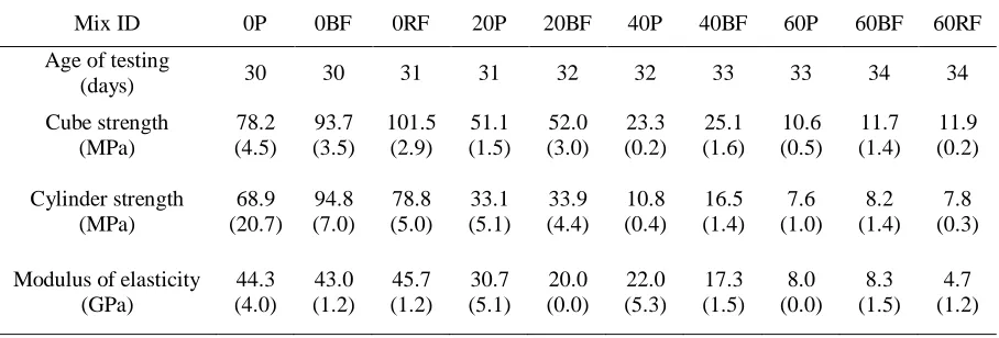
18 Table 5. Mechanical properties of all concrete mixes tested under compression
367
368
Mix ID 0P 0BF 0RF 20P 20BF 40P 40BF 60P 60BF 60RF
Age of testing
(days) 30 30 31 31 32 32 33 33 34 34
Cube strength (MPa) 78.2 (4.5) 93.7 (3.5) 101.5 (2.9) 51.1 (1.5) 52.0 (3.0) 23.3 (0.2) 25.1 (1.6) 10.6 (0.5) 11.7 (1.4) 11.9 (0.2) Cylinder strength (MPa) 68.9 (20.7) 94.8 (7.0) 78.8 (5.0) 33.1 (5.1) 33.9 (4.4) 10.8 (0.4) 16.5 (1.4) 7.6 (1.0) 8.2 (1.4) 7.8 (0.3)
Modulus of elasticity (GPa) 44.3 (4.0) 43.0 (1.2) 45.7 (1.2) 30.7 (5.1) 20.0 (0.0) 22.0 (5.3) 17.3 (1.5) 8.0 (0.0) 8.3 (1.5) 4.7 (1.2) 369
4.2.1 Cube strength
370
It can be observed that the addition of steel fibres in conventional concrete increases the 371
compressive strength by 20% when a blend of MSF and RTSF (20 kg/m3 and 20 kg/m3) is used,
372
and by 30% when only RTSF is used (40 kg/m3). Steel fibres enhanced the compressive strength 373
by controlling the tensile transverse strains developed, due to the Poisson effect during axial 374
loading, thus delaying micro-crack coalescence and eventually unstable propagation that causes 375
compression failure. RTSF are particularly effective in this respect, possibly due to their random 376
geometry and better distribution in the mix due to their small diameters. 377
378
The replacement of fine and coarse aggregates with rubber particles had, as expected, a significant 379
adverse effect on the compressive strength. The drop in the compressive strength, with respect to 380
the control mix, was around 35%, 70% and 86% for mixes with 20%, 40% and 60% aggregate 381
replacement, respectively. The reduction in compressive strength can be mainly attributed to the 382
lower stiffness and higher Poisson ratio of rubber compared to conventional aggregates, and the 383
weak bond between cement paste and rubber [20, 21]. Under axial load, rubber particles develop 384
19 cracks in the cement paste, thus accelerating the unstable propagation of cracks and causing 386
failure at a lower load compared to conventional concrete. The differences in elastic 387
characteristics and possibly poor bonding conditions between cement paste and rubber particles 388
may also lead to uneven stress distribution in the concrete. 389
390
The addition of fibres into the RuC mixes did not have a significant effect on the compressive 391
strength. Compared to the RuC mixes that had the same amount of rubber and did not contain 392
fibres, the increase in the compressive strength as a result of the addition of MSF and/or RTSF 393
was 1.7% for 20BF, 7.6% for 40BF, 10% for 60BF and 12% for 60RF. This indicates that the 394
compressive strength of the SFRRuC is dominated by the amount of rubber, while sensitivity to 395
steel fibre content is very low. 396
397
4.2.2 Stress-strain characteristics
398
Figure 4 shows representative axial stress-strain curves (up to the peak stress) for selected tested 399
cylinders. As there are considerable local strain variations and global bending issues, the 400
cylinders that displayed better agreement between global and local axial strains and lower level 401
of bending during loading were chosen. As pointed out by other researchers [11, 25], there is a 402
very high variability in the recorded results, mainly due to large accidental bending, resulting 403
from uneven bearing surfaces and/or due to the non-uniform distribution of the rubber particles 404
20 406
Figure. 4 Stress-strain curves of the concrete assessed 407
408
It can be seen from Table 5 and Figure 4 that as the rubber content increases, the peak stress and 409
the initial slope of the stress-strain curves substantially decreases. For the applications considered 410
in this study (i.e. concrete pavements and slabs on grade), the loss in compression strength is not 411
as important as the increase in deformability, provided that sufficient flexural strength is 412
maintained. 413
414
Figure 5 shows that the modulus of elasticity of rubberised concretes (ERuC) without fibre
415
addition, normalised with respect to the control concrete mix (Econtrol), reduces with an increased
416
rubber content. Such reduction in stiffness can be attributed to the lower stiffness of rubber 417
particles (compared to conventional aggregates) and to the higher air content, as confirmed in 418
section 4.1.2. An exponential curve is also shown to provide an equation for the estimation of 419
modulus of elasticity. The reduction in elastic stiffness may be undesirable in some structural 420
applications, but it can help develop new structural solutions, in particular at the soil structure 421
21 423
Figure 5. Correlation between the normalized modulus of elasticity of rubberised concretes as a 424
function of rubber aggregate content 425
426
As shown in Table 5, the effect of steel fibres on compressive stiffness is not conclusive. 427
However, steel fibres overall tend to increase the peak stress and corresponding strain (apart from 428
mix 20BF). This enhancement is expected due to the steel fibre ability to control the development 429
of transverse deformations. 430
431
The addition of rubber and steel fibres had a more significant effect on the failure mode (Figure 432
6). Whilst the plain concrete specimens failed in a sudden and brittle manner, the RuC specimens 433
failed in a much more ductile manner. This can be attributed to the relatively low elastic modulus 434
of the rubber particles, which increases the deformation capacity before cracking, but also to the 435
tensile resistance of rubber aggregates. The RuC specimens with steel fibres exhibited more (and 436
thinner) vertical cracks at failure, compared to the ones without fibres. This suggests that ductility 437
22 439
Figure 6. Typical compression failure of tested concrete cylinders 440
441
4.3 Flexural behaviour
442
The failure mode was the same for all specimens and a typical example is shown in Figure 7; a 443
single crack initiated at the notch of the mid-span section and propagated vertically towards the 444
compression zone. 445
446
447
Figure 7. Photograph showing a typical flexural failure of the tested concrete prisms 448
449
The mean values (average of three prisms) of strain capacity, flexural strength and elastic 450
modulus are shown in Table 6. The elastic theory was used to determine the flexural modulus of 451
elasticity by using the secant modulus of the load-deflection curves (from 0 to 30% of the peak 452
load). 453
[image:23.612.196.419.414.542.2]23 Table 6. Mechanical properties of all concrete mixes tested in flexural
454
Mix ID 0P 0BF 0RF 20P 20BF 40P 40BF 60P 60BF 60RF
Age of testing
(days) 60 60 61 61 62 62 63 63 64 64
Flexural strength (MPa) 7.3 (0.2) 9.2 (0.8) 9.5 (0.7) 5.6 (0.1) 6.9 (0.9) 3.7 (0.4) 6.6 (0.4) 2.6 (0.2) 5.5 (0.1) 4.2 (0.3)
Modulus of elasticity (GPa) 46.8 (2.1) 47.5 (1.0) 48.3 (3.34) 29.3 (2.31) 34.0 (3.1) 18.3 (2.6) 23.5 (5.9) 8.1 (1.6) 8.3 (1.1) 10.1 (2.5)
Strain capacity, fmax
(mm) 0.04 (0.01) 0.06 (0.02) 0.22 (0.07) 0.05 (0.01) 0.26 (0.32) 0.06 (0.01) 1.34 (0.21) 0.14 (0.03) 1.32 (0.74) 0.55 (0.36) 455
4.3.1 Flexural Strength
456
Flexural strength values are compared in Figure 8. The addition of steel fibres enhanced the 457
flexural strength by 26% for 0BF and 30% for 0RF, with respect to the control mix. This 458
improvement was anticipated as the steel fibres act as flexural reinforcement. 459
460
Figure 8. Flexural strength of the tested concrete mixes 461
462
Consistent with the reported by other authors [25, 36, 59], replacing the fine and coarse 463
[image:24.612.168.450.382.615.2]24 of the RuC mixes without fibres, 20P, 40P and 60P, was 23%, 49% and 64% lower than that of 465
the conventional concrete, respectively. As for the compressive strength, the reduction in flexural 466
strength may be attributed to the lack of good bonding conditions between the rubber particles 467
and the cement paste, as well as the low stiffness and higher Poisson’s ratio of rubber (nearly 0.5) 468
compared to conventional aggregates [20, 21]. The high Poisson’s ratio means that the rubber 469
once in tension will contract faster than concrete in the lateral direction, facilitating loss of bond. 470
The low stiffness also means that the rubber contributes very little in tension at the low strain at 471
which the cement matrix cracks. 472
473
The addition of steel fibres in the RuC resulted in a substantial enhancement of its flexural 474
strength, therefore mitigating the adverse effect of partially replaced natural aggregates by 475
recycled rubber particles. By comparing the flexural strength of the SFRRuC mixes, 20BF, 40BF, 476
60BF and 60RF, with the flexural strength of the RuC mixes without fibres, 20P, 40P and 60P, 477
it is noted that the flexural strength was increased by 23%, 78%, 111.5% and 61.5%, respectively. 478
Although the flexural strength gain of the 60RF mix is not as high as the 60BF mix, it still 479
provides sufficient flexural strength for SFRRuC pavements and slabs on grade and can 480
potentially lead to more sustainable solutions by eliminating the need for virgin materials. 481
482
Figure 9 shows the normalised compressive and flexural strength for all mixes, with respect to 483
the control mix (concrete without fibres and/or rubber). It is clear that the loss in compressive 484
strength as a result of the addition of rubber is more pronounced than the flexural strength loss. 485
Even without the fibres, the loss in flexural resistance of the RuC is less than the loss in 486
compressive strength; this indicates that the rubber is making a modest contribution to the tensile 487
25 enhanced and hence, considerable flexural resistance is developed even when large volumes of 489
rubber are present. 490
491
[image:26.612.152.463.148.382.2]492
Figure. 9 Normalised strength as a function of rubber volume in the concrete 493
494
4.3.2 Modulus of elasticity
495
The values obtained from the flexural tests are in general similar to those from the compressive 496
tests. As expected, there is a small increase (up to 3%) in the elastic modulus when fibres are 497
added. A significant reduction in the elastic modulus is also found for the RuC mixes, with the 498
decrease being almost proportional to the amount of rubber content. In particular, the modulus of 499
elasticity of the RuC mixes without fibres, 20P, 40P and 60P, was 37.4%, 60.9% and 82.7% 500
lower than that of the control mix, respectively. The addition of steel fibres into RuC mixes 501
recovered only marginally part of the modulus of elasticity loss. This confirms that, within the 502
elastic domain, the inclusion of rubber particles plays a dominant role on flexural stiffness, 503
26
4.3.3 Strain capacity
505
The flexural strain capacity was assessed by examining the stress-deflection curves. The 506
deflection fmax corresponding to the peak stress, fmax, is taken as a relevant indicator of strain
507
capacity [33]. It is evident from table 6 that the strain capacity is enhanced by the addition of 508
fibres. For instance, the fmax valuefor the control mix, 0P, was 0.04 mm, while the fmax values
509
for 0BF and 0RF mixes were 0.06 and 0.22 mm, respectively. This enhancement can be explained 510
by the bridging action of the fibres. The strain capacity of the RTSF mix, 0RF, was higher than 511
that of the blend fibres mix, 0BF, possibly due to the larger number of RTSF fibres bridging the 512
cracks. 513
514
The strain capacity also increases with higher rubber contents in the concrete. Compared to the 515
control mix, 0P, the fmax of the RuC mixeswas increased by 25%, 50% and 250% for 20P, 40P
516
and 60P, respectively. Turatsinze et al. [33] explained such behaviour by the ability of rubber 517
particles to reduce stress concentration at the crack tip, thus delaying the coalescence and 518
propagation of micro-cracks. Mixes with steel fibres and rubber developed the highest strain 519
capacity values, indicating a synergy between rubber and steel fibres in enhancing strain capacity. 520
521
4.3.4 Residual flexural strength and energy absorption behaviour
522
The load versus deflection curves shown in Figure 10 confirm that the post-peak branches of the 523
SFRC prisms without rubber were significantly enhanced as a result of the inclusion of fibres. 524
The fibres continue bridging the cracks and resisting their opening even after the peak load, 525
dissipating energy through the pull-out mechanism. 526
27 528
Figure. 10 Average stress versus deflection curves for all concrete mixes studied 529
530
Although rubber particles had an adverse effect on the flexural strength of the concrete prisms, 531
they improved slightly the post-peak energy absorption. This enhancement can be explained by 532
the ability of the rubber particles to undergo large deformation in tension and promote high 533
energy absorption. As a result of the interlocking and friction at fibre–matrix and fibre-rubber 534
interfaces, steel fibres substantially enhanced the post-peak energy absorption and dissipation of 535
RuC mixes, which at large displacements show higher flexural capacity than the specimens 536
without rubber. 537
538
As expected, concrete prisms with a blend of fibres (MSF and RTSF) show superior post-peak 539
energy absorption behaviour than those with RTSF alone. RTSF are overall better distributed and 540
28 and develop. Though the difference in performance is not obvious for normal concrete in Figure 542
10, this is well demonstrated at 60% rubber content when the 60BF controls the cracks much 543
better than 60RF. In another study [43], the mixes with blend fibres are shown to outperform both 544
the RTSF and MSF only mixes. 545
546
To further examine the post-peak energy absorption behaviour of the mixes, the residual flexural 547
strength (fRi) and the characteristic residual flexural strength values (fRi,c) were obtained (see
548
Table 7) at given intervals of CMOD (0.5, 1.5, 2.5, 3.5) according to RILEM recommendation 549
[52]. The residual flexural strength can be considered a measure of toughness or even ductility of 550
the SFRC mixes. Higher values of fR,i mean higher post-cracking load carrying capacity and
551
higher ductility. The characteristic residual flexural strength fRi,c accounts for the variability of
552
the residual flexural strength results. SFRRuC mixes showed a lower rate of reduction in residual 553
strength than FRC mixes. This may be attributed to the presence of rubber particles that prolong 554
the crack path and increase the contact area of the failure surface with the rubber particles, which 555
make some contribution to the tensile strength, but also enable the steel fibres to engage better 556
across the crack. 557
[image:29.612.78.538.551.722.2]558
Table 7. Residual and characteristic flexural strength values of concrete assessed 559
Mix
No. Mix ID
fRi (MPa) fRi, c (MPa) fib (2010) classification
fR1 fR2 fR3 fR4 fR1,c fR2,c fR3,c fR4,c fR3,c
/
fR1,c Class1 0P - - - -
2 0BF 8.1 5.3 3.5 2.7 6.1 3.5 2.4 1.2 0.39 - (< 0.5)
3 0RF 8.4 5.2 3.7 2.8 8.3 4.7 2.9 1.8 0.35 - (< 0.5)
4 20P - - - -
5 20BF 6.5 6.6 5.4 4.3 4.4 4.9 3.3 2.3 0.75 4.4b
6 40P - - - -
7 40BF 5.9 6.4 6.4 5.4 4.9 5.8 5.6 4.6 1.14 4.9d
8 60P - - - -
9 60BF 5.1 5.4 5.3 4.7 4.4 5.2 5.1 3.8 1.16 4.4d
10 60RF 4.1 3.7 3.1 2.6 3.6 3.2 2.8 2.6 0.78 3.6b
* a if 0.5 fR3,c/fR1,c 0.7; b if 0.7 ≤ fR3,c/fR1,c ≤0.9; c if 0.9 ≤ fR3,c/fR1,c ≤1.1;d if 1.1 ≤ fR3,c/fR1,c ≤3;e if ≤fR3,c/fR1,c
29 According to fib model code [58] for structural applications with normal and high-strength 561
concrete, SFRC can be classified according to the post-cracking residual strength (considering 562
the value of fR1,c), and the ratio fR3,c
/
fR1,c. The higher the value of fR1,c and/or the ratio fR3,c/
fR1,c,563
the higher the class. As observed in Table 7, mixes 40BF and 60BF show the best overall 564
performance among all mixes, whereas SFRC mixes (without rubber) can not be classified as 565
their fR3,c
/
fR1,c ratio is less than 0.5. Nevertheless, all SFRC mixes (conventional and rubberised)566
fulfilled the requirements of EN 14889-1 [60] – 1.5 MPa at 0.5 mm CMOD and 1.0 MPa at 3.5 567
mm CMOD – and could be used for practical applications. 568
569
The aim of this study is to develop a more flexible Portland cement concrete pavement. However, 570
as flexible pavement standards/specifications relate to asphalt concrete, it is not possible to use 571
them for a direct comparison, though the flexural performance of SFRRuC is far superior to that 572
of asphalt concrete. Hence, SFRRuC pavements, though flexible, should comply with 573
standards/specifications for rigid pavements. The major issue here is that the rigid pavement 574
standards relay on the compressive and flexural strengths. Though all SFRRuC mixes studied 575
here meet the flexural strength characteristics, as described in pavement design standard BS EN 576
13877-1[54], not all of them can meet the compressive requirements. However, provided that 577
durability requirements are met, this should not be a big issue but would require modification on 578
the standard. 579
580
4.4 Free shrinkage behaviour
581
Typical curves of total shrinkage versus time are shown in Figure 11. The vertical dotted line 582
30 Eurocode 2 [61] for conventional concrete (accounting for temperature and humidity) are also 584
included for comparison. 585
586
Both conventional concrete and SFRC mixes show lower autogenous and drying shrinkage 587
strains than those predicted by Eurocode 2 (EC2). The difference between predicted and actual 588
values for these mixes can be attributed to the presence of high quantities of silica fume and fly 589
ash, not accounted for in the Eurocode 2 equation. It is also clear that the addition of rubber 590
increases the overall shrinkage strains at 57 days by 15.5% for 20P, 59% for 40P and 127% for 591
60P. This increase in free shrinkage strain with increasing rubber content is due to the lower 592
stiffness of rubber particles compared to conventional aggregates, which reduces the overall 593
internal restrain. The higher porosity and diffusivity of rubberised concrete prims can also 594
contribute to increasing the rate of moisture loss and accelerating drying shrinkage. 595
596
[image:31.612.162.493.397.696.2]597
31
5 Conclusions
599
This study assessed the fresh state and mechanical properties of steel-fibre reinforced rubberised 600
concretes (SFRRuC), in which waste tyre rubber partially replaced aggregates, and blends of 601
manufactured and recycled tyre steel fibres were used as reinforcement. Based on the 602
experimental results, the following conclusions can be drawn: 603
The replacement of conventional aggregates with rubber particles reduces workability and 604
unit weight, and increases air content of the fresh concrete mixes. Steel fibres further 605
lower workability and increase air content, whilst marginally increasing unit weight. 606
The mechanical properties (compressive and flexural strength, as well as the modulus of 607
elasticity) decrease with increasing rubber content. Steel fibres in appropriate amounts 608
(up to 40 kg/m3) enhance the mechanical properties of conventional concrete (up to 30% 609
compressive strength) and provide modest increases in the modulus of elasticity. 610
Free shrinkage strain increases with increasing rubber content as a result of the lower 611
stiffness of rubber particles. 612
In rubberised concrete, the addition of steel fibre reinforcement mitigates the loss in 613
flexural strength (from 50% to 9.6% loss, compared to conventional concrete) and slightly 614
improves compressive strength and modulus of elasticity (up to 12.5% and 28.4%, 615
respectively), hence, they are an important component when RuC is to be used for 616
structural purposes. 617
Concrete strain capacity and post-peak energy absorption behaviour are enhanced by the 618
addition of fibres and are further improved by the inclusion of rubber, completely 619
transforming the flexural performance of RuC and enabling it to resist structural loads. 620
A high performance (class d according to fib 2010 model code [58]) and highly flexible 621
32 blended fibres (20 kg/m3 of MSF and 20 kg/m3 of RTSF), suitable for pavement 623
applications. 624
It is concluded that SFRRuC is a promising candidate material for use in structural concrete 625
applications with increased toughness and flexibility requirements, such as road pavements and 626
slabs on grade. Future work should be directed towards investigating the long-term performance 627
of this innovative concrete in aggressive environments. 628
629
Acknowledgements
630The research leading to these results has received funding from the European 393 Union Seventh 631
Framework 394 Programme [FP7/2007- 2013] under grant agreement n° 603722. The authors 632
would also like to thank all of the material suppliers and companies for their in-kind contribution 633
of materials for this research study: Tarmac UK, Sika, Aggregate Industries UK Ltd and Twincon 634
Ltd. The first author PhD studies are sponsored by King Saud University and Ministry of 635
Education in the Kingdom of Saudi Arabia. 636
33
References
638
[1] ETRA, The European Tyre Recycling Association. 2016, Available at: http://www.etra-eu.org [Last
639
accessed: 02/01/2018].
640
[2] Council of the European Union, Council Directive 1999/31/EC of 26 April 1999 on the landfill of
641
waste. 1999.
642
[3] Eldin, N.N. and A.B. Senouci. Measurement and prediction of the strength of rubberized concrete.
643
Cement and Concrete Composites 1994;16(4):287-298.
644
[4] Benazzouk, A., et al. Thermal conductivity of cement composites containing rubber waste particles:
645
Experimental study and modelling. Construction and Building Materials 2008;22(4):573-579.
646
[5] Mohammed, B.S., et al. Properties of crumb rubber hollow concrete block. Journal of Cleaner
647
Production 2012;23(1):57-67.
648
[6] Council of the European Union, Council Directive 2008/98/EC on waste (Waste Framework
649
Directive). 2008.
650
[7] Bravo, M. and J. de Brito. Concrete made with used tyre aggregate: durability-related performance.
651
Journal of Cleaner Production 2012;25:42-50.
652
[8] Thomas, B.S. and R.C. Gupta. A comprehensive review on the applications of waste tire rubber in
653
cement concrete. Renewable and Sustainable Energy Reviews 2016;54:1323-1333.
654
[9] Son, K.S., I. Hajirasouliha, and K. Pilakoutas. Strength and deformability of waste tyre rubber-filled
655
reinforced concrete columns. Construction and Building Mateials. 2011;25(1):218-226.
656
[10] Youssf, O., et al. An experimental investigation of crumb rubber concrete confined by fibre
657
reinforced polymer tubes. Construction and Building Materials 2014;53:522-532.
658
[11] Raffoul, S., et al. Optimisation of rubberised concrete with high rubber content: An experimental
659
investigation. Construction and Building Materials 2016;124:391-404.
660
[12] Bompa, D., et al. Experimental assessment and constitutive modelling of rubberised concrete
661
materials. Construction and Building Materials 2017;137:246-260.
662
[13] Grinys, A., et al. Fracture of concrete containing crumb rubber. Journal of Civil Engineering and
663
Management 2013;19(3):447-455.
664
[14] Liu, F., et al. Mechanical and fatigue performance of rubber concrete. Construction and Building
665
Materials 2013;47:711-719.
666
[15] Sukontasukkul, P. and C. Chaikaew. Properties of concrete pedestrian block mixed with crumb
667
rubber. Construction and Building Materials 2006;20(7):450-457.
668
[16] Ling, T.C., H.M. Nor, and S.K. Lim. Using recycled waste tyres in concrete paving blocks.
669
Proceedings of the ICE - Waste and Resource Management 2010;163(1):37-45.
670
[17] Issa, C.A. and G. Salem. Utilization of recycled crumb rubber as fine aggregates in concrete mix
671
design. Construction and Building Materials 2013;42:48-52.
672
[18] Güneyisi, E., et al. Evaluation of the rheological behavior of fresh self-compacting rubberized
673
concrete by using the Herschel–Bulkley and modified Bingham models. Archives of Civil and
674
Mechanical Engineering 2016;16(1):9-19.
675
[19] Flores-Medina, D., N.F. Medina, and F. Hernández-Olivares. Static mechanical properties of waste
676
rests of recycled rubber and high quality recycled rubber from crumbed tyres used as aggregate
677
in dry consistency concretes. Materials and Structures 2014;47(7):1185-1193.
678
[20] Khatib, Z. and F. Bayomy. Rubberized portland cement concrete. Journal of Materials in Civil
679
Engineering 1999;11(3):206-213.
680
[21] Khaloo, A.R., M. Dehestani, and P. Rahmatabadi. Mechanical properties of concrete containing a
681
high volume of tire–rubber particles. Waste Management 2008;28(12):2472-2482.
682
[22] Richardson, A.E., K. Coventry, and G. Ward. Freeze/thaw protection of concrete with optimum
683
rubber crumb content. Journal of Cleaner Production 2012;23(1):96-103.
684
[23] Batayneh, M., I. Marie, and I. Asi. Promoting the use of crumb rubber concrete in developing
685
countries. Waste Management 2008;28(11):2171-2176.
686
[24] Bignozzi, M.C. and F. Sandrolini. Tyre rubber waste recycling in self-compacting concrete. Cement
687
and Concrete Research 2006;36(4):735-739.
34
[25] Ganjian, E., M. Khorami, and A.A. Maghsoudi. Scrap-tyre-rubber replacement for aggregate and
689
filler in concrete. Construction and Building Materials 2009;23(5):1828-1836.
690
[26] USFD, Thin wire reinforcement for concrete’. B.P. Application, Editor. 2001: UK. 691
[27] Pilakoutas, K., K. Neocleous, and H. Tlemat. Reuse of tyre steel fibres as concrete reinforcement.
692
Proceedings of the ICE-Engineering Sustainability 2004;157(3):131-138. ISSN 1478-4629.
693
[28] Neocleous, K., et al. Fibre-reinforced roller-compacted concrete transport pavements. Proceedings
694
of the ICE-Transport 2011;164(TR2):97-109.
695
[29] Tlemat, H., K. Pilakoutas, and K. Neocleous. Stress-strain characteristic of SFRC using recycled
696
fibres. Materials and structures 2006;39(3):365-377.
697
[30] Angelakopoulos, H., K. Neocleous, and K. Pilakoutas. Steel fibre reinforced roller compacted
698
concrete pavements. Challenges for Civil Construction 2008:16-18.
699
[31] Aiello, M.A., et al. Use of steel fibres recovered from waste tyres as reinforcement in concrete:
Pull-700
out behaviour, compressive and flexural strength. Waste management 2009;29(6):1960-1970.
701
[32] Graeff, A.G., et al. Fatigue resistance and cracking mechanism of concrete pavements reinforced
702
with recycled steel fibres recovered from post-consumer tyres. Engineering Structures
703
2012;45:385-395.
704
[33] Turatsinze, A., J.L. Granju, and S. Bonnet. Positive synergy between steel-fibres and rubber
705
aggregates: Effect on the resistance of cement-based mortars to shrinkage cracking. Cement and
706
Concrete Research 2006;36(9):1692-1697.
707
[34] Nguyen, T., A. Toumi, and A. Turatsinze. Mechanical properties of steel fibre reinforced and
708
rubberised cement-based mortars. Materials & Design 2010;31(1):641-647.
709
[35] Ganesan, N., J.B. Raj, and A. Shashikala. Flexural fatigue behavior of self compacting rubberized
710
concrete. Construction and Building Materials 2013;44:7-14.
711
[36] Xie, J.-h., et al. Compressive and flexural behaviours of a new steel-fibre-reinforced recycled
712
aggregate concrete with crumb rubber. Construction and Building Materials 2015;79:263-272.
713
[37] Medina, N.F., et al. Mechanical and thermal properties of concrete incorporating rubber and fibres
714
from tyre recycling. Construction and Building Materials 2017;144:563-573.
715
[38] BSI, EN 197-1: Cement — Part 1: Composition, specifications and conformity criteria for common
716
cements. BSI 389 Chiswick High Road, London W4 4AL, UK. 2011.
717
[39] ASTM, C136: Standard test method for sieve analysis of fine and coarse aggregates. ASTM
718
International, West Conshohocken, PA. doi:10.1520/C0136-06. 2006.
719
[40] BSI, EN 1097-6: Tests for mechanical and physical properties of aggregates, Determination of
720
particle density and water absorption. BSI 389 Chiswick High Road, London W4 4AL, UK. 2013.
721
[41] BSI, EN 1097-3: Tests for mechanical and physical properties of aggregates, Determination of loose
722
bulk density and voids. BSI 389 Chiswick High Road, London W4 4AL, UK. 1998.
723
[42] BSI, EN 933-3: Tests for geometrical properties of aggregates, Determination of particle shape –
724
Flakiness index. BSI 389 Chiswick High Road, London W4 4AL, UK. 2012.
725
[43] Hu, H., et al. Mechanical properties of SFRC using blended manufactured and recycled tyre steel
726
fibres. Construction and Building Materials 2018;163:376-389.
727
[44] BSI, EN 12350-2: Testing fresh concrete, Part 2: Slump-test. BSI 389 Chiswick High Road, London
728
W4 4AL, UK. 2009.
729
[45] BSI, EN 12350-7: Testing fresh concrete, Part 7: Air content — Pressure. BSI 389 Chiswick High
730
Road, London, W4 4AL, UK. 2009.
731
[46] BSI, EN 12350-6: Testing fresh concrete Part 6: Density. BSI 389 Chiswick High Road, London,
732
W4 4AL, UK. 2009.
733
[47] BSI, EN 12390-2: Testing hardened concrete, Part 2: Making and curing specimens for strength tests.
734
BSI 389 Chiswick High Road, London W4 4AL, UK. 2009.
735
[48] BSI, EN 14651:+A1:2007: Test method for metallic fibre concrete — Measuring the flexural tensile
736
strength (limit of proportionality (LOP), residual) ICS 91.100.30. BSI 389 Chiswick High Road,
737
London W4 4AL, UK. 2005.
738
[49] BSI, EN 12390-3: Testing hardened concrete, Part3: Compressive strength of test specimens. BSI
739
389 Chiswick High Road, London W4 4AL, UK. 2009.
35
[50] Garcia, R., et al. Seismic retrofitting of RC buildings using CFRP and post-tensioned metal straps:
741
shake table tests. Bulletin of Earthquake Engineering 2015:1-27.
742
[51] JCI. SF-4: Method of test for flexural strength and flexural toughness of steel fiber reinforced
743
concrete. Japan Concrete Institute, Tokio, Japan. 1984.
744
[52] RILEM, TC 162-TDF: Test and design methods for steel fibre reinforced concrete, Bending test,
745
Final Reccomendation. Materials and Structures: 35, 579-582. 2002.
746
[53] BSI, EN 12617-4: Products and systems for the protection and repair of concrete structures — Test
747
methods —Part 4: Determination of shrinkage and expansion. BSI 389 Chiswick High Road,
748
London W4 4AL, UK. 2002.
749
[54] BSI. EN 13877-1. Concrete pavements Part 1: Materials. BSI 389 Chiswick High Road London W4
750
4AL UK. 2013.
751
[55] BSI, BS EN 206-1. Concrete —Part 1: Specification, performance,production and conformity. BSI
752
389 Chiswick High Road London W4 4AL. 2000.
753
[56] Siddique, R. and T.R. Naik. Properties of concrete containing scrap-tire rubber–an overview. Waste
754
Management 2004;24(6):563-569.
755
[57] Abaza, O.A. and Z.S. Hussein. Flexural Behavior of Steel Fiber-Reinforced Rubberized Concrete.
756
Journal Of Materials In Civil Engineering 2015;28(1):04015076.
757
[58] fib, Model Code for Concrete Structures 2010. Federal Institute of Technology Lausanne–EPFL,
758
Section Génie Civil, Swizerland. 2010. p. 978-3.
759
[59] Aiello, M.A. and F. Leuzzi. Waste tyre rubberized concrete: properties at fresh and hardened state.
760
Waste Manag 2010;30(8-9):1696-704.
761
[60] BSI, EN 14889-1: Fibres for concrete — Part 1: Steel fibres — Definitions, specifications and
762
conformity. BSI 389 Chiswick High Road, London W4 4AL, UK. 2006.
763
[61] BSI, EN1992-1-1. Eurocode 2: Design of concrete structures — Part 1-1: General rules and rules for
764
buildings. BSI 389 Chiswick High Road, London W4 4AL, UK. 2004.
765
766