promoting access to White Rose research papers
White Rose Research Online
[email protected]
Universities of Leeds, Sheffield and York
http://eprints.whiterose.ac.uk/
This is a copy of the final published version of a paper published via gold open access
in
Engineering Structures
.
This open access article is distributed under the terms of the Creative Commons
Attribution Licence (
http://creativecommons.org/licenses/by/4.0/
) which permits
unrestricted use, distribution, and reproduction in any medium, provided the
original work is properly cited.
White Rose Research Online URL for this paper:
http://eprints.whiterose.ac.uk/85981
Published paper
Londono, J.M., Neild, S.A. and Wagg, D.J. (2014)
Using a damper amplification factor
Using a damper amplification factor to increase energy dissipation in
structures
Julián M. Londoño
a,⇑, Simon A. Neild
a, David J. Wagg
a,ba
Department of Mechanical Engineering, University of Bristol, Queens Building, University Walk, Bristol BS8 1TR, UK
b
Department of Mechanical Engineering, University of Sheffield, Sir Frederick Mappin Building, Mappin Street, Sheffield S1 3JD, UK
a r t i c l e
i n f o
Article history:
Received 1 April 2014 Revised 2 September 2014 Accepted 17 November 2014 Available online 8 December 2014
Keywords:
Damping amplification Energy dissipation
Real-time dynamic substructuring test Structural control
a b s t r a c t
Fluid dampers are an important tool for dissipating unwanted vibrations in a range of engineering struc-tures. This paper examines the effects of amplifying the displacements transferred to a non-linear dam-per, to increase the effectiveness of the damper in a range of situations commonly encountered in civil engineering structures. These include, (i) the ability to ‘‘fine tune’’ the required damping for a particular size damper, (ii) the ability to have a set of the same size dampers, but with different amplification factors to achieve a specific damping task, and (iii) to increase the sensitivity of the damper to small movements which effectively extends the range over which the damper works. Through numerical simulations and experimental tests conducted on a non-linear damper, we quantify the potential advantages of adding an amplification factor and the range of parameters where the benefit to this device is significant. The example of a two-storey structure is used as a test case and real-time dynamic substructuring tests are used to assess the complete system performance using a range of different amplification factors. The results show that the structural performance is most improved for frequencies close to resonance and that the amplification factor has an effective limit that for the case considered in this study is of approximately 3. The effects of the mechanism compliance are also assessed.
Ó2014 The Authors. Published by Elsevier Ltd. This is an open access article under the CC BY license (http:// creativecommons.org/licenses/by/3.0/).
1. Introduction
The elimination of unwanted vibrations from civil engineering structures has been of growing importance in recent years, partic-ularly for slender or otherwise flexible structures. This is impor-tant, not only for reducing the dynamic response of structures under extreme loads, but also for increasing the system reliability
and ensuring human comfort during everyday dynamic loads[1].
Over recent decades improvement in damper technology have been seen. It is typical to split such technologies into three classes;
(i) passive, (ii) active and (iii) semi-active devices[2]. In this paper,
the focus is on using passive fluid dampers, in combination with a motion amplification mechanism. The purpose of the amplification factor is to increase the sensitivity of the damper and therefore
extend its range of operation[3]. It can also be used to ‘‘tune’’
the required damping value of a single or multiple dampers. In practice, the amplification factor can be achieved by using a
variety of in-built mechanisms. In [3]for instance, dampers are
connected to the structure through lever arms and double chevron
braces. By selecting suitable lever arm ratios, the authors highlight that a single size of damper can be used throughout a building while still achieving the optimal response performance associated with using a range of damper sizes. However, the use of a chevron brace can be visually intrusive. A similar lever arm and chevron
brace setup, this time utilising two dampers, is reported in[4],
where the effects of brace stiffness is discussed. In[5]a brace
sys-tem in which tensioned cables impose amplified structural dis-placements on dampers is presented. It is reported that this system can efficiently enhance damping without modifying the structural stiffness. However due to geometric limitations, the
scheme is only able to deliver relatively low amplification. In[6]
pre-tensioned diagonal bracing bars are connected to angular lever arms located at the lower corners of each bay. While offering a rel-atively unobtrusive solution, the performance is shown to be highly dependent on both the brace stiffness and its angle of inclination.
A toggle-brace-damper was proposed by Taylor Devices inc. in
[7]and analysed in[8]. Despite being particularly sensitive to the
brace stiffness, toggles can offer relatively high amplification fac-tors. However, due to geometry considerations, the authors sug-gest a practical amplitude range of between 2 and 5. The use of MR dampers in conjunction with the toggle configuration is
http://dx.doi.org/10.1016/j.engstruct.2014.11.019 0141-0296/Ó2014 The Authors. Published by Elsevier Ltd.
This is an open access article under the CC BY license (http://creativecommons.org/licenses/by/3.0/). ⇑Corresponding author.
E-mail addresses: [email protected](J.M. Londoño), Simon.Neild@ bristol.ac.uk(S.A. Neild),[email protected](D.J. Wagg).
Contents lists available atScienceDirect
Engineering Structures
discussed in [9]. They observed that the toggle configuration is likely to raise the structural stiffness. Scissor-jack-damper systems offer a compact method for high amplification, see for example the
detailed assessment in[10]. However they also add stiffness and
are sensitive to both pivot movement and elastic deformation. Another approach involves the use of gears. For example, a device constructed by coupling together two rack and two pinions having
differing radii is described in[11]. The authors claim compactness
and high amplification capability for the system. A further
attrac-tive approach, Hwang et al.[12], combines rotational inertia
damp-ers with toggle bracing. In this case the amplification system is not only compact but also able to decrease the effective mass and stiff-ness of the structure.
Note that all of the mechanisms reported above have been mod-elled in the literature as constant amplification factors, i.e., coeffi-cients that linearly scale the velocity transferred from the structure to the damper.
Here we are interested in the use of an amplifier in conjunction with a nonlinear damper for vibration suppression. Rather than studying a particular amplification mechanism, we wish to analyse how the combined nonlinearity and amplification changes the effectiveness of the vibration suppression. A further question is whether this behaviour results in an amplification limit beyond which no significant performance gain is obtained. Knowledge of this limit is needed to ensure well-behaved and cost-effective amplification mechanisms. As such we consider a generic amplifier capable of linearly scaling the displacement.
By considering a wide range of amplification factors and several loading conditions, we show both numerically and experimentally the advantages of amplifying the structural velocity transmitted to a small-scale non-linear damper. Using this approach we can iden-tify the range of parameters where the most benefit is achieved when an amplification mechanism is added to the structure. We use the example of a two-storey structure to assess a whole system performance by considering a small non-linear damper attached to an amplification mechanism within the structure. A particular issue we consider is that of using an amplification mechanism-damper system with a smaller mechanism-damper, to reduce the amount of stiction caused by large damper seals. The effects of the mecha-nism compliance are also assessed.
This paper is organised as follows. Section 2 introduces the
structural model and highlights the effects of amplifying the veloc-ity transferred to the non-linear dampers via numerical
simula-tions. Section 3 presents details of the real-time dynamic
substructuring, the experimental testing technique that has been used in this work. The numerical findings are validated experimen-tally through a series of experiments that physically test a real
non-linear damper in Section4. Finally, the conclusions and further
remarks of this work are presented in Section5.
2. Energy dissipation in dampers and the amplification factor
A basic approach for reducing structural vibration in buildings is to fit some supplemental damping devices into the structure. This concept takes advantage of the structure’s own motion to pro-duce relative movement within the damping devices. In response, those devices are expected to develop considerable local damping forces that act to dissipate a significant amount of energy—see for
example[13]and references therein. If the relative motion of the
damper can be amplified, then for small structural movements, a larger damping force can be achieved. Or, the same damping force can be achieved, but using a smaller damper.
Typical fluid dampers have a piston/plunger within a cylinder and two sets of seals. The seals are designed to maintain alignment of the damper and stop the fluid from leaking. In terms of damper
performance the seals act as sources of non-linearity and friction effects. One consequence of the seals is that static friction will restrict the range of velocities when the damper will move. This results in two different types of behaviour (i) sticking when the force is below the static friction level and (ii) a slipping phase, after the damper is mobilised, where energy is effectively dissipated. It should be noted that negligible energy is dissipated in the damper during sticking and if there is a large range where this behaviour occurs the damper performance is degraded.
The major seismic building codes impose strict limits on the maximum permissible inter-storey drift of buildings when subject to earthquake excitation. While structural safety is the primary dri-ver for these limits, minimising damage to non structural elements is also a factor when considering moderate or minor earthquakes. In fact, during moderate seismic events, structures are expected to exhibit just small lateral displacements. If the damper has been designed for a large event, small deformation may not even mobi-lise the damper, due to the internal friction forces that must be overcome prior to mobilisation of the damper.
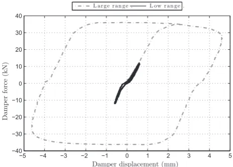
Since energy is dissipated during the slipping phase rather than a sticking phase, one advantage of amplifying the structure’s motion is to use a smaller dampers with lower static friction so that the slipping phase occurs at lower displacements (and
veloc-ities). The concept is illustrated inFig. 1, which shows
experimen-tal results from a large-scale non-linear viscous fluid damper (NLD). Two experimental tests, one over a low and the other a high displacement range are shown. It can be seen that no slip occurs over the low range and hence the NLD effectively acts as a nonlin-ear spring rather than as an energy dissipator. The NLD has a peak
force of 60 kN and a maximum stroke of ±15 mm[14]. When acting
at a range of low displacements, the damper behaves as a very stiff spring, meanwhile at large displacements the damper goes into the slipping phase, describing the well-known hysteretic loop and dis-sipating energy. Therefore, in this situation, using smaller dampers and amplifying the structural motion transferred to them could significantly increase the dampers efficacy.
2.1. Two-storey example
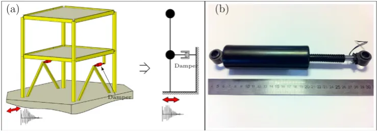
As an example structure we consider a symmetric two-storey building with two NLD attached at the first floor as shown in Fig. 2a. The structure and damper size were tuned to produce an equivalent additional damping of approximately 20% of the critical damping ratio when the system oscillating at the frequency of the first linear mode. We note that this damper configuration may not
−5 −4 −3 −2 −1 0 1 2 3 4 5
−40 −30 −20 −10 0 10 20 30 40
Damper displacement (mm)
Damper force (kN)
[image:3.595.321.553.563.729.2]L a r g e r a n g e . L ow r a n g e .
represent the optimal arrangement for the studied system, never-theless this configuration is sufficient to gain a better understand-ing of the advantages of includunderstand-ing an amplification mechanism together with the nonlinear dampers into a structure. The building has been modelled as a linear two degree-of-freedom (DOF)
sys-tem by using Eq.(1), whereM;CandKrepresent the mass,
damp-ing and stiffness matrices;€x;x_ andxare the acceleration, velocity
and displacement of the structure relative to the ground; €xg is
the ground acceleration,C¼ ½1;1TandK¼ ½1;0T.
M€xþCx_þKx¼ M
C
€xgþK
FD ð1ÞThe structure is considered to be made of steel, the damping is fixed to be 3% of critical and the natural frequencies to be 2.086 and 5.46 Hz; and:
M¼ 1 0
0 1
145:8 Ns
2
m; C¼
248:9 83
83 165:9
N s
m;
K¼ 2 1
1 1
65:5 kN
m ð2Þ
In this study MR dampers are used in their passive mode (with the voltage set to zero), as the NLDs. The reason for selecting MR dampers is that the nonlinear dynamic modelling and associated parameter fitting for this type of damper is well developed. Here
we use a simplified version of the Dahl model[15, p.152]as shown
in Eq.(3), whereFDis the damper force in Newtons;x_Dis the
rel-ative velocity across the damper in cm/s; t is time in seconds,
w2 ð1;1Þis a dimensionless parameter which models the
hyster-esis in the force-velocity plane and
q
is a coefficient that controlsthe rate of change of the hysteric variablew. Note that both kx
andkw are voltage-dependent parameters[16].
FDðtÞ ¼kxð
v
Þx_DðtÞ þkwðv
ÞwðtÞ_
wðtÞ ¼
q
ðx_DðtÞ jx_DðtÞjwðtÞÞð3Þ
This model has proven to be accurate for describing the nonlinear behaviour of real dampers and captures the damper’s response in the force-velocity plane while allowing a reduced number of parameters if compared against traditional hysteretic models like
Bouc–Wen (Further details in[17]). A comprehensive work
demon-strating the identification procedure can be found in[18].
Representing a generic amplification mechanism by means of anamplification factor(AF), enables us to write the velocity across the damper in terms of the relative velocity of the first floor of the structure, giving
_
xD¼AFx_1 ð4Þ
Hence the modified equations of the damper and amplifier com-bined are given by
FDðtÞ ¼AFkxð
v
Þx_1ðtÞ þkwðv
ÞwðtÞ_
wðtÞ ¼
q
AFðx_1ðtÞ jx_1ðtÞjwðtÞÞð5Þ
For the physical damper discussed in Section3, with a constant
voltage of 0 V, the following set of parameters has been identified:
kxð0Þ ¼9:78 N s cm1,kwð0Þ ¼60:11 N,
q
¼47:95 cm1. It is worthnoting that the amplification factor only directly modifies the
veloc-ity-dependant terms in Eq.(5). This does not alter the magnitude of
the termkwbut only the speed at whichwðtÞchanges from1 to 1.
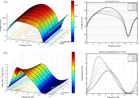
To simulate the dynamic response of the structure, a numerical model has been developed in Mathworks Simulink. A range of numerical simulations have been performed to capture the changes
in the structural behaviour. The parameterAFhas been varied from
1 to 4 while different harmonic ground motion excitations have been applied to the system covering frequencies from 1.5 Hz and
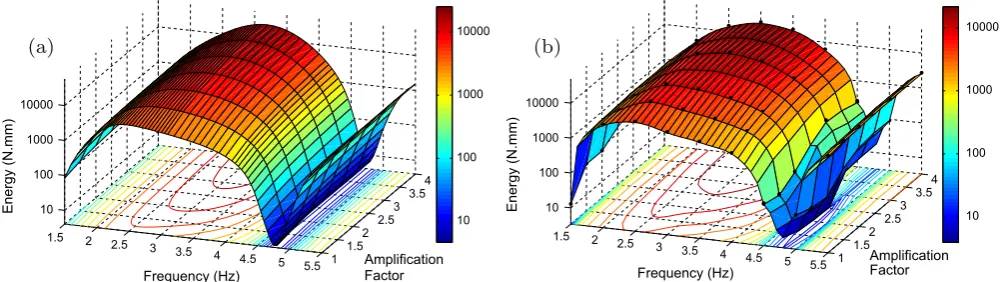
up to 5.5 Hz.Fig. 3a shows the numerical results for the steady-state
energy dissipated per cycle for a single NLD. Similarly,Fig. 3b
pre-sents the numerical results for the maximum displacement (drift) reached at the level of the first floor. Note that the closest edge of
both surfaces correspond to the case of no amplification (AF¼1).
The numerical results indicate that the larger the amplification factor, the larger the amount of energy dissipated by the damper and the lower the maximum storey drift reached. As expected, by amplifying the structural velocity across the dampers, a better structural performance is achieved as passive dampers move more readily into the slipping phase, generating larger forces and dissi-pating much more energy.
Nonetheless, the benefits of amplifying the velocity are only sig-nificant for a certain range of frequencies. Particularly, we observed that real advantages in terms of energy are achieved in between the first natural frequency and the anti-resonance fre-quency of the base structure (about 4.7 Hz). If reducing the floor displacement is the primary target when including the amplifica-tion mechanism, it must be optimised for a frequency slightly higher than the natural frequency of the original structure (around 2.4 Hz in the example). On the other hand, if increasing the energy dissipated is the main objective, then the frequency of interest in the example should be around 3.2 Hz. The simulations shown here are for a sinusoidal ground motion of 5 mm amplitude. Qualita-tively very similar results were found for excitation amplitudes of 2.5 and 10 mm.
In order to compare this result with physical experiments, we
tested a system equipped with real NLD.Fig. 2b shows the
mag-netorheological (MR) damper that was used in the experimental tests, a model RD-8040-1 produced by the Lord Corporation (see http://www.lord.com). It is characterised by a stroke of 55 mm and damping forces up to 2447 N (peak-to-peak) at 1 A. Note that we do not apply any voltage to the damper coils such that the dam-per can be considered as a purely passive NLD. In the next section, we introduce the experimental technique that was used and in
Section4the experimental results are presented.
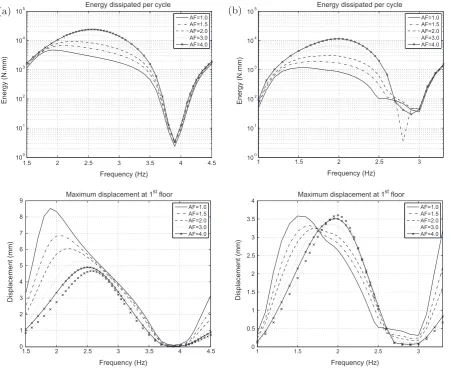
Two more examples are considered here. The aim is to show
that the practical limit value of the AF beyond which the
amplification mechanism loses effectiveness, is influenced by the Damper
Damper
[image:4.595.108.478.67.199.2](a)
(b)
relative magnitude of the damping force with respect to the structural responses. In other words, it depends on the criteria used to size the dampers. Keeping the same damper size and similar additional damping ratio as a point of reference, the second
example corresponds to the structural system presented in (2)
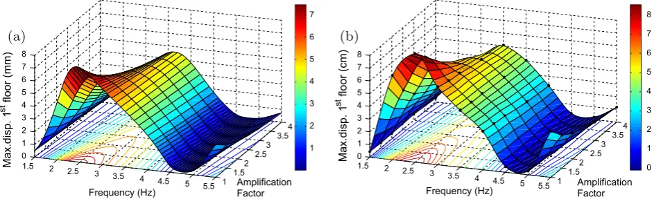
with the masses increased by 50%. Fig. 4(a) presents numerical
results of the energy dissipated per cycle in the steady-state in a single NLD (upper panel) along with the maximum drift reached at the first floor (lower panel). The third example corresponds to
a 4-DOF system with same masses and stiffnesses as in(2)and
nonlinear dampers located at the first and second floors. The
numerical results are presented in Fig. 4(b). These results show
again that there exists a practical limit for the amplification factor, beyond which the benefits of including the amplification
mechanism are diminished. Larger values of theAFcould be in fact
detrimental as shown in the lower panel ofFig. 4(b), where the
maximum displacement starts to rise as theAFexceeds the value
of approximately 2.
3. Real-time dynamic substructuring testing
Real-time dynamic substructuring (RTDS) is an efficient and cost-effective testing technique able to assess the rate-dependent behaviour of systems. RTDS provides the ability to physically test mechanical components that are difficult to model numerically within a structure (due to, for example, their nonlinear behaviour) [19,20]. These components can be tested at real scale and in
real-time to fully capture any rate dependency[21]. They are extracted
from the original system to form the ‘‘physical substructure’’, while the remaining part of the system is simulated numerically (the
‘‘numerical substructure’’). In RTDS forces and displacements must be matched at the interface between the two substructures, there-fore dynamic transfer and measurement systems are included (see Fig. 5). The challenging issue is to minimise interface errors and therefore ensure that the physical and the numerical substructures
together behave in the same way as the whole system[22,23].
In the experiments reported in this paper, the numerical sub-structure is the 2-DOF system described above (with no added damper), the physical substructure consists of the MR damper act-ing in passive mode and the transfer system is a electro-mechani-cal actuator. To satisfy compatibility and equilibrium at the interface, the interface displacement is calculated by the numerical substructure and posed to the physical substructure. The force required to impose this displacement is then passed back to the numerical substructure.
3.1. Delay, stability and accuracy
The success of a RTDS simulation is dependent on the perfor-mance of the actuator and its associated controller, whose dynam-ics introduce both timing and amplitude errors into the signal
affecting the accuracy of the results [24]. Several authors have
shown that these errors may be propagated throughout the
simu-lation and may cause the test to become unstable[25,26]. Time
delay compensation schemes, which make corrections on the actu-ator command signal, have commonly been used to overcome this
issue[27]. The most-widely used procedure in RTDS simulation is
the polynomial approximation method introduced by Horiuchi
et al. [28–30]. Results of comparable quality using different
compensation procedures can also be found in [31–33]. Due to
1.5 2
2.5 3
3.5 4
4.5 5 5.5 1
1.5 2
2.5 3
3.5 4
10 100 1000 10000
Amplification Factor Frequency (Hz)
Energy (N.mm)
10 100 1000 10000
(a)
1.5 2 2.5 3 3.5 4 4.5 5 5.5
100
101
102 103
104
105
Frequency (Hz)
Energy (N.mm)
Energy dissipated per cycle
AF=1.0 AF=1.5 AF=2.0 AF=3.0 AF=4.0
1.5 2
2.5 3
3.5 4
4.5 5 5.5 1
1.5 2
2.5 3
3.5 4
0 1 2 3 4 5 6 7 8
Amplification Factor
Frequency (Hz)
Max.disp. 1
st floor (mm)
1 2 3 4 5 6 7
(b)
1.5 2 2.5 3 3.5 4 4.5 5 5.5
0 1 2 3 4 5 6 7 8
Frequency (Hz)
Displacement (cm)
Maximum displacement at 1st floor
[image:5.595.73.533.69.394.2]AF=1.0 AF=1.5 AF=2.0 AF=3.0 AF=4.0
its simplicity and efficiency, a polynomial extrapolation scheme has been used in these experiments. Over the frequency range of interest, the actuator delay was found to be approximately constant at about 18 ms. We found that a first-order polynomial with four data points (with a spacing of 1 ms) can be used to successfully forward predict the command displacement.
Full numerical simulations have been completed to assess the effects of including both the damper nonlinearity and the delay
compensation in the RTDS loop. InFig. 6the curves labelled ‘‘No
delay’’ (solid line) correspond to the ideal RTDS outputs when nei-ther delay nor compensation are considered; similarly, the curves
labelled as ‘‘Delayed’’ (dashed line) correspond to the outputs when
the actuator dynamics are modelled as a constant delay and a first-order polynomial is used to predict the actuator command signal. Fig. 6a shows the displacement time history at the first floor along
with the damper force from formula(3); this simulation considers
an actuator delay of 18 ms,AF= 1 and full delay compensation. The
inclusion of both time lag and full delay compensation does not seem to alter the results significantly. However, when considering
higher values ofAF oscillations, which increase exponentially in
amplitude, are observed in the simulation (See Fig. 6b where
AF¼3:25).
We found that this phenomenon is due to the difficulty for a continuous-signal based predictor to cope with the near-piecewise response of the NLD. We note that the use of a higher-order poly-nomial does not provide any benefit as this just forces the system to undergo larger oscillations. By reducing the forward prediction,
the tests can be stabilised for higher values ofAFbut with slightly
reduced levels of accuracy.Fig. 6c shows a simulation where the
prediction scheme compensates for 50% of the actuator delay. Note that the undesired oscillations decrease at shorter prediction times but they are always present to some extent.
Owing to the trade-off between stability, prediction andAF, the
degree of forward prediction has individually selected for each
experimental test presented in the next section. AsAFincreases,
the forward prediction is reduced in such a way that the system was kept as close to the stability boundary as possible to maximise accuracy.
1.5 2 2.5 3 3.5 4 4.5
100
101
102
103
104
105
Frequency (Hz)
Energy (N.mm)
Energy dissipated per cycle
AF=1.0 AF=1.5 AF=2.0 AF=3.0 AF=4.0
(a)
1 1.5 2 2.5 3
100
101
102
103
104
105
Frequency (Hz)
Energy (N.mm)
Energy dissipated per cycle
AF=1.0 AF=1.5 AF=2.0 AF=3.0 AF=4.0
(b)
1.5 2 2.5 3 3.5 4 4.5
0 1 2 3 4 5 6 7 8 9
Frequency (Hz)
Displacement (mm)
Maximum displacement at 1st floor
AF=1.0 AF=1.5 AF=2.0 AF=3.0 AF=4.0
1 1.5 2 2.5 3
0 0.5 1 1.5 2 2.5 3 3.5 4
Frequency (Hz)
Displacement (mm)
Maximum displacement at 1st floor
[image:6.595.69.521.67.437.2]AF=1.0 AF=1.5 AF=2.0 AF=3.0 AF=4.0
Fig. 4.Energy dissipated per cycle in a single damper in the first floor and the maximum structural displacement at the first floor: (a) if mass in Eq.(2)is increased by 50%; (b) if a 4-DOF systems is considered.
[image:6.595.39.283.486.582.2]4. Experimental results
The experimental rig shown inFig. 7has carefully been set up to
emulate the structural system described in Section 2. A Dspace
DS1104 board was used to run the numerical substructure and for-ward prediction written in Simulink.
The aim of these experiments was to physically test a system equipped with real NLDs and evaluate the effects of considering a motion amplification factor. Just as for the numerical simulations, the structural model has been evaluated under ground excitation using harmonic motion and the mechanical amplifier has been modelled as a constant gain.
4.1. Harmonic excitation
Several tests were conducted to capture the changes in the sys-tem behaviour when the velocity transferred to the damper is
amplified.Fig. 8shows the damper response for 4 different levels
of amplification when the structure is excited at 3.0 Hz and 5 mm. As can been seen, the nature of the damper response is highly non-linear. From the figure it is also clear how much energy
is dissipated by the damper asAFincreases. For the experiments,
we have considered ground motion excitations at frequencies from 1.5 to 5.5 Hz in steps of 0.5 Hz. Higher frequencies were not con-sidered here since they fall outside the range of the test equipment. The system has been evaluated for the cases when the velocity transferred to the damper was amplified by factors of 1.0, 1.5, 2.0, 3.0 and 4.0. This range of parameters was also determined in
accordance with the physical limitation of the damper (after amplification the maximum damper displacement is 23 mm).
Figs. 9b and 10b summarise the experimental steady-state responses. In these plots, the black dots correspond to direct exper-imental measurements while the surfaces were constructed within the range of the discrete set of known data points by using the cubic spatial interpolation method. The numerical results have been included again to facilitate a direct comparison (panel a) in both figures). The figures demonstrate very good agreement between the numerical estimations and the experimental results.
0 0.5 1 1.5 2 2.5 3
−20 −10 0 10 20 S to re y Di sp (mm)
Predicting 0.018s.τ= 0.018s.AF= 1
2.05 2.1 2.15−15
−14 −13 −12 −11 −10 −9 No delay Delayed
0 0.5 1 1.5 2 2.5 3
−1000 −500 0 500 1000 Time (s) Da m p er F o rc e (N )
2.05 2.1 2.15−500
0 500
Time (s)
(a)
0 0.5 1 1.5 2 2.5 3
−10 −5 0 5 10 S to re y Di sp (mm)
Predicting 0.018s.τ= 0.018s.AF= 3.25
2.05 2.1 2.15−10
−8 −6 −4 −2 No delay Delayed
0 0.5 1 1.5 2 2.5 3
−2000 −1000 0 1000 2000 Time (s) Da m p er F o rc e (N )
2.05 2.1 2.15−1000
−500 0 500 1000 1500 Time (s)
(b)
0 0.5 1 1.5 2 2.5 3
−10 −5 0 5 10 S to re y Di sp (m m )
Predicting 0.009s.τ= 0.018s.AF= 3.25
2.05 2.1 2.15−10
−8 −6 −4 −2 No delay Delayed
0 0.5 1 1.5 2 2.5 3
−1500 −1000 −500 0 500 1000 1500 Time (s) Da mp er F o rc e (N )
2.05 2.1 2.15−1000
[image:7.595.54.548.66.419.2]−500 0 500 1000 1500 Time (s)
(c)
[image:7.595.322.551.454.608.2]Fig. 6.Oscillations arise when errors in predicting piecewise signals are amplified by theAF.
The experimental tests confirm that the amplification of the structural displacements and velocities transferred to the supple-mental dampers can improve the structural performance in a range of frequencies that goes from just beyond the natural frequency to the anti-resonance frequency of the unmodified structure. From both numerical and experimental results it has been observed that no significant benefits are achieved for amplification factors greater than 3 as only limited further reduction in structural response is achieved beyond this point. This suggests that well-behaved mechanism-damping systems are required to offer amplification up to approximately 3 times, beyond this value the mechanism would be over-specified for this damper setup.
4.2. Seismic excitation
We now consider the case of the structure subjected to seismic base excitation. The earthquake considered is compatible with the elastic response spectrum provided by Eurocode 8 for very dense sand, gravel, or very stiff clay (soil type B) and for high and moder-ate seismicity regions (Seismic Zone 1), but has been scaled in
amplitude as shown in Fig. 11a in accordance with the physical
constrains of the damper and experimental rig. We note that the earthquake was chosen so that the maximum frequency content of the ground motion occurs around the first natural frequency
of the structure.Fig. 11b presents a typical response when carrying
out a substructuring simulation of the whole system with the selected seismic load. The plots correspond to the case of an ampli-fication factor of 2.5. The total energy dissipated during the stron-gest part of the earthquake (5 to 20 s) is 78.99 Nm.
The experimental results considering seismic base excitation
are summarised inFig. 12, where both the total energy dissipated
by the dampers and the maximum structural displacement at the first floor have been plotted against the amplification factor. As the amplification factor increases the system exhibits a significant reduction of the structural displacements and a corresponding increase in the amount of energy dissipated during the earthquake. As with the harmonic excitation results, the effects of increasing the amplification become less at higher amplification factors. Note that considering softer soil conditions, or equivalently earthquakes with frequency contents outside the considered frequency range, will not have significant impact in the structural response and
therefore the study regarding the effects of the AF will be less
meaningful.
4.3. Effects of the mechanism flexibility
The flexibility of the amplification mechanism could signifi-cantly reduce its own efficiency and therefore diminish the damp-ing capability of the mechanism-dampdamp-ing arrangement. Due to the mechanism compliance, the amplified displacement that is actu-ally transferred from the amplification device to the damper is reduced. Compliance also introduces a phase offset (with reference to the structural forcing displacement) in the damper response. These issues have been studied when searching for more accurate
design procedures of brace-damper systems[34].
To assess the impact of compliance on the overall system per-formance, we introduce the mechanism stiffness effect into the model by way of a linear spring. This flexible element was located
−20 −10 0 10 20
−400 −300 −200 −100 0 100 200 300 400
Damper displacement (mm)
Da
mp
er
fo
rc
e
(N
)
0 100 200 300 400
0 50 100 150 200 250 300 350
Velocity (mm/s)
Da
mp
er
fo
rc
e
(N
)
AF= 1.0
AF= 2.0
AF= 3.0
[image:8.595.116.467.67.227.2]AF= 4.0
Fig. 8.Damper response at different values of the amplification factorAFwhen structure is excited at 3.0 Hz.
1.5 2 2.5
3 3.5 4
4.5 5 5.5 1
1.5 2
2.5 3
3.5 4
10 100 1000 10000
Amplification Factor Frequency (Hz)
Energy (N.mm)
10 100 1000 10000
(a)
1.5 2
2.5 3
3.5 4 4.5
5 5.5 1
1.5 2
2.5 3
3.5 4
10 100 1000 10000
Amplification Factor Frequency (Hz)
Energy (N.mm) 10
100 1000 10000
(b)
[image:8.595.41.543.596.737.2]in series between the generic amplification mechanism and the damper. Simulations in which the ratio of mechanism stiffness
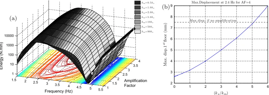
(km) to structural stiffness (ks) was varied have been conducted.
Fig. 13a shows how the energy dissipated per cycle is affected as
the ratioks=km increases. The surfaces are coloured in grayscale
with the darkest colour corresponding to the more compliant mechanism configuration.
Fig. 13b shows the maximum displacement at the first floor for
the structure when considering a mechanism withAF= 1 and
vary-ingks=kmat the frequency of 2.4 Hz that corresponds to the peak
displacement for the system without mechanism (AF= 1,
km! 1). The dashed line indicates the level of displacement
reached when no amplification mechanism is considered. The plot shows the degradation in the structural response as the
1.5 2
2.5 3
3.5 4
4.5 5
5.5 1 1.5
2 2.5
3 3.5
4
0 1 2 3 4 5 6 7 8
Amplification Factor Frequency (Hz)
Max.disp. 1
st floor (mm)
Max.disp. 1
st floor (cm)
1 2 3 4 5 6 7
(a)
1.5 2
2.5 3
3.5 4
4.5 5
5.5 1 1.5
2 2.5
3 3.5
4
0 1 2 3 4 5 6 7 8
Amplification Factor Frequency (Hz)
0 1 2 3 4 5 6 7 8
[image:9.595.67.539.68.212.2](b)
Fig. 10.Maximum structural displacement at the first floor. (a) Numerical simulations. (b) Experimental results.
0 1 2 3 4 5 6 7 8 9 10
0 0.5 1 1.5 2 2.5x 10
4
Frequency (Hz)
Fourier spectrum
Earthquake - base excitation
0 10 20 30 −200
−100 0 100 200
T i m e ( s )
Accel
e
r
a
t
io
n
(
c
m
/
s
2)
(a)
6 8 10 12 14 16 18
−20 −10 0 10 20
Damper displ. (mm)
Substructuring Test - Earthquake input
6 8 10 12 14 16 18
−0.2 −0.1 0 0.1 0.2 0.3
Damper force (kN)
Time (s)
−20 −10 0 10
−0.3 −0.2 −0.1 0 0.1 0.2
Damper displ. (mm)
Damper force (kN)
[image:9.595.69.541.253.418.2](b)
Fig. 11.(a) Earthquake ground motion used in the tests. (b) Experimental response of the system forAF= 2.5.
1 1.5 2 2.5 3 3.5 4
4 5 6 7 8 9 10 11x 10
4
Amplification Factor
Energy (N.mm)
Total Energy dissipated in the Earthquake
(a)
1 1.5 2 2.5 3 3.5 4
5 6 7 8 9 10 11
Amplification Factor
Displacement (mm)
Maximum displacement at the 1stfloor
[image:9.595.109.499.471.640.2](b)
mechanism flexibility increases. For stiffnesseskmlower than 20% of the floor stiffness, the beneficial effect of the mechanical amplification is no longer seen – in fact the presence of the mech-anism is deleterious in this case.
5. Conclusions
In this paper we investigated the advantages of amplifying the structural velocity transmitted to non-linear dampers (NLD) fitted within a structure. We tested a small NLD attached to an amplifi-cation mechanism and presented results for a series of numerical simulations. These findings were verified experimentally using real-time dynamic substructuring with a real damper. We found that the structural performance can be improved if an amplifica-tion mechanism-damping system is added to increase the sensitiv-ity of the NLD as they spend more time in the slipping phase. Nonetheless, such benefits are only significant for a range of fre-quencies that goes from just beyond the first natural frequency to the anti-resonance frequency of the unmodified structure and for amplification factors between 1 and 3 in the cases studied. Beyond this range the amplification mechanism would be over-specified for the tested setup. We note that this practical limit of the amplification factor is influenced not only by the nonlinear characteristics of the damper, but also by the relative magnitude of the damping force with respect to the structural responses, i.e. it depends on the criteria used to size the dampers.
Excitation frequencies higher than 5.5 Hz could not be tested experimentally since they fall outside the range of the test equip-ment. Yet numerical simulations indicate no significant
improve-ment above that range for any value ofAF. This can be explained
by the fact that the overall system response (including the mecha-nism) is moved away from the resonance region.
The impact of the mechanism compliance on the vibration sup-pressions was also studied. We showed the degradation in the structural response as the mechanism flexibility increases. We found that for mechanisms with an effective stiffnesses lower than 20% of the structural stiffness, the beneficial effect of the mechan-ical amplification is no longer seen. This demonstrates the need to carefully design the mechanism to achieve the wanted perfor-mance in terms of energy dissipation and storey drift.
Acknowledgement
J.M. Londoño was funded by the Royal Society and the Royal Academy of Engineering of the United Kingdom through a Newton
International Fellowship (http://www.newtonfellowships.org/).
S.A. Neild is funded by a EPSRC fellowship, EP/K005375/1. This financial support is gratefully acknowledged.
References
[1]Spencer BF, Nagarajaiah S. State of the art in structural control. ASCE J Struct Eng 2003;129(7):845–56.
[2] Wagg DJ, Neild SA. A review of non-linear structural control techniques. Proc Inst Mech Eng C J Mech Eng Sci 2011;225(4):759–70. http://dx.doi.org/ 10.1177/2041298310392855.
[3] Ribakov Y, Gluck J, Gluck N. Practical design of mdof structures with supplemental viscous dampers using mechanical levers. In: Proc of the 8th ASCE specialty conference on probabilistic mechanics and structural reliability; 2000.
[4] Ribakov Y, Reinhorn AM. Design of amplified structural damping using optimal considerations. J Struct Eng 2003;129(10):1422–7.http://dx.doi.org/10.1061/ (ASCE)0733-9445(2003)129:10(1422).
[5] Gluck J, Ribakov Y. Active viscous damping system with amplifying braces for control of MDOF structures. Earthquake Eng Struct Dynam 2002;31(9): 1735–51.http://dx.doi.org/10.1002/eqe.202.
[6] Zasso A, Aly A, Resta F. MR dampers with lever mechanism for response reduction in high-rise buildings under wind loads. In: Proc. 5th European & African conference on wind engineering, Florence, Italy; 2009.
[7] Constantinou MC, Tsopelas P, Hammel W. Testing and modeling of an improved damper configuration for stiff structural systems, Tech. rep., <http://www.taylordevices.com/Tech-Paper-archives/literature-pdf/50-Testing-Modeling.pdf>, Center for Industrial Effectiveness and Taylor Devices, Inc.; 1997.
[8]Constantinou MC, Tsopelas P, Hammel W, Sigaher AN. Toggle-brace-damper seismic energy dissipation systems. J Struct Eng ASCE 2001;127(2):105–12. [9] Lee SH, Min KW, Chung L, Lee SK, Lee MK, Hwang J-S, Choi S-B, Lee H-G.
Bracing systems for installation of MR dampers in a building structure. J Intell Mater Syst Struct 2007;18(11):1111–20.http://dx.doi.org/10.1177/1045389 X06072371.
[10] Sßigaher AN, Constantinou MC. Scissor-jack-damper energy dissipation system. Earthquake Spectra 2003;19(1):133–58.http://dx.doi.org/10.1193/1.1540999. [11] Berton S, Bolander JE. Amplification system for supplemental damping devices in seismic applications. J Struct Eng ASCE 2005;131(6):979–83. http:// dx.doi.org/10.1061/(ASCE)0733-9445(2005)131:6(979).
[12] Hwang JS, Kim J, Kim YM. Rotational inertia dampers with toggle bracing for vibration control of a building structure. Eng Struct 2007;29(6):1201–8.http:// dx.doi.org/10.1016/j.engstruct.2006.08.005.
[13] Hwang JS. Seismic design of structures with viscous dampers. In: International training programs for seismic design of building structures. National Center of Research on Earthquake Engineering of Taiwan; 2000.
[14] Spizzuoco M, Londoño JM, Serino G. An experimental campaign on a passively controlled building structure. In: Proceedings of the fourth european conference of structural control. vol. 2, St. Petersburg, Russia, isbn: 978-5-904045-10-4; 2008. p. 950–9.
[15]Ikhouane F, Rodellar J. Systems with hysteresis: analysis. In: Identification and control using the Bouc–Wen model. John Wiley & Sons, Inc; 2007.
[16] Aguirre N, Ikhouane F, Rodellar J. Proportional-plus-integral semiactive control using magnetorheological dampers. J Sound Vib 2011;330(10):2185–200. http://dx.doi.org/10.1016/j.jsv.2010.11.027.
[17] Ikhouane F, Dyke SJ. Modeling and identification of a shear mode magnetorheological damper. Smart Mater Struct 2007;16(3):605–16.http:// dx.doi.org/10.1088/0964-1726/16/3/007.
[18] Ikhouane F, Rodellar J. On the hysteretic Bouc–Wen model. Part II: Robust parametric identification. Nonlinear Dynam 2005;42(1):79–95. http:// dx.doi.org/10.1007/s11071-005-0070-x.
1.5 2
2.5 3
3.5 4
4.5 5
5.5 1 1.5
2 2.5
3 3.5
4
1 10 100 1000 10000
Amplification Factor Frequency (Hz)
Energy (N.mm)
km= 0 . 5ks
km= 1 . 0ks
km= 2 . 0ks
km= 5 . 0ks
km= 1 0ks
km= 5 0ks
km= 9 0ks
(a)
0 1 2 3 4 5 6
2 3 4 5 6 7 8 9
Max .dis p. if no amplific at ion
Max.Displacement at 2.4 Hz for AF=4
(ks/km)
Max. disp.1
stfloor (mm)
[image:10.595.60.526.68.232.2](b)
Fig. 13.Effects of the mechanism stiffness (km) on the system performance: (a) impact on the energy dissipated by the damper; (b) impact on the maximum structural
[19]Bursi OS, Wagg DJ, editors. Modern testing techniques for structural systems dynamics and control. CISM international centre for mechanical sciences, vol. 502. Springer; 2008.
[20] Shao X, Reinhorn AM. Unified formulation for real time dynamic hybrid testing. In: Yuan Y, Cui J, Mang H, editors. Computational structural engineering. Netherlands: Springer; 2009. p. 201–8. http://dx.doi.org/ 10.1007/978-90-481-2822-8_23.
[21] Gawthrop PJ, Wallace MI, Neild SA, Wagg DJ. Robust real-time substructuring techniques for under-damped systems. Struct Control Health Monit, vol. 14. john Wiley & Sons, Ltd; 2007. p. 591–608. http://dx.doi.org/10.1002/ stc.174.
[22] Neild SA, Stoten DP, Drury D, Wagg DJ. Control issues relating to real-time substructuring experiments using a shaking table. Earthquake Eng Struct Dynam, vol. 34. john Wiley & Sons, Ltd.; 2005. p. 1171–92.http://dx.doi.org/ 10.1002/eqe.473.
[23] Shao X, Reinhorn A, Sivaselvan M. Real-time hybrid simulation using shake tables and dynamic actuators. J Struct Eng 2011;137(7):748–60. http:// dx.doi.org/10.1061/(ASCE)ST.1943-541X.0000314.
[24] Wallace MI, Sieber J, Neild SA, Wagg DJ, Krauskopf B. Stability analysis of real-time dynamic substructuring using delay differential equation models. Earthquake Eng Struct Dynam, vol. 34. john Wiley & Sons, Ltd; 2005. p. 1817–32.http://dx.doi.org/10.1002/eqe.513.
[25] Wagg DJ, Stoten DP. Substructuring of dynamical systems via the adaptive minimal control synthesis algorithm. Earthquake Eng Struct Dynam 2001;30:865–77.http://dx.doi.org/10.1002/eqe.44.
[26] Londoño JM, Serino G, Wagg DJ, Neild SA, Crewe AJ. On the assessment of passive devices for structural control via real-time dynamic substructuring. Struct Control Health Monit 2012;19(8):701–722http://dx.doi.org/10.1002/ stc.464.
[27] Bursi O, He L, Lamarche C, Bonelli A. Linearly implicit time integration methods for real-time dynamic substructure testing. J Eng Mech 2010;136(11):1380–9. http://dx.doi.org/10.1061/(ASCE)EM.1943-7889.0000182.
[28] Horiuchi T, Inoue M, Konno T, Namita Y. Real-time hybrid experimental system with actuator delay compensation and its application to a piping system with energy absorber. Earthquake Eng Struct Dynam, vol. 28 (10). John Wiley & Sons, Ltd; 1999. p. 1121–41. http://dx.doi.org/10.1002/(SICI)1096-9845(199910)28:10<1121::AID-EQE858>3.0.CO;2-O.
[29] Nakashima M, Masaoka N. Real-time on-line test for MDOF systems. Earthquake Eng Struct Dynam, vol. 28 (4). John Wiley & Sons, Ltd; 1999. p. 393–420. http://dx.doi.org/10.1002/(SICI)1096-9845(199904)28:4<393::AID-EQE823>3.0.CO;2-C.
[30] Darby AP, Williams MS, Blakeborough A. Stability and delay compensation for real-time substructure testing. J Eng Mech 2002;128(12):1276–84.http:// dx.doi.org/10.1061/(ASCE)0733-9399(2002)128:12(1276).
[31]Ahmadizadeh M, Mosqueda G, Reinhorn AM. Compensation of actuator delay and dynamics for real-time hybrid structural simulation. Earthquake Eng Struct Dynam, vol. 37. john Wiley & Sons, Ltd; 2008. p. 21–42.
[32] Wallace MI, Wagg DJ, Neild SA. An adaptive polynomial based forward prediction algorithm for multi-actuator real-time dynamic substructuring. Proc Roy Soc A Math Phys Eng Sci 2005;461(2064):3807–26.http://dx.doi.org/ 10.1098/rspa.2005.1532.
[33] Bonnet PA, Williams MS, Blakeborough A. Compensation of actuator dynamics in real-time hybrid tests. Proc Inst Mech Eng I J Syst Control Eng 2007;221(2):251–64.http://dx.doi.org/10.1243/09596518JSCE301.