Bachelor of Mechanical Engineering (with Honours)
2018
Faculty of Mechanical Engineering
MATERIAL SELECTION FOR CAR DISC BRAKE PAD
USING MCDM METHOD
MATERIAL SELECTION FOR CAR DISC BRAKE PAD USING MCDM METHOD
YEOH CHUN SIAN
A thesis submitted
in fulfillment of the requirements for the Bachelor of Mechanical Engineering (with Honours)
Faculty of Mechanical Engineering
UNIVERSITI TEKNIKAL MALAYSIA MELAKA
DECLARATION
I declare that this project report entitled “Material Selection for Car Brake Pad Using
MCDM Method” is the result of my own work except as cited in references.
Signature: ……….
Name : ………...
DEDICATION
To my beloved mother and father, i am sincerely thank you for supporting me to complete
APPROVAL
I hereby declare that I have read this project report and in my opinion this project is sufficient
in terms of scope and quality for the award of Bachelor of Mechanical Engineering (with
Honours)
Signature : ………...
Supervisor Name : ………...
i
ABSTRACT
The function of the automotive braking system is to slow down the speed of the vehicle.
Normally the braking system consists of brake discs and paired with various composite brake
pads. The aim of this research is to use material selection method to select optimum material
for replacing asbestos fibre in the application of automotive brake pad. The methods used
for selection of materials is VIKOR method and compare against standard brake pad
properties. The mechanical properties of brake pad such as tensile strength, wear, thermal
conductivity, the coefficient of friction and hardness are the criteria in material selection.
The alternative materials were evaluated among natural fibre reinforcement composites such
as palm kernel fibre, date palm fibre, sisal fibre and bamboo fibre. The VIKOR method result
shows that date palm fibre composite is the most appropriate material for replacing asbestos
ii
ABSTRAK
Fungsi sistem brek automotif adalah untuk memperlahankan kelajuan kenderaan. Biasanya
sistem brek terdiri daripada cakera brek dan dipasangkan dengan pelbagai pad brek komposit.
Tujuan kertas ini adalah menggunakan kaedah pemilihan bahan untuk memilih bahan yang
optimum untuk menggantikan serat asbes dalam aplikasi pad brek automotif. Kaedah yang
digunakan untuk pemilihan bahan adalah kaedah VIKOR dan bandingkan dengan ciri pad
brek standard. Sifat mekanikal pad brek seperti kekuatan tegangan, pakai, kekonduksian
terma, pekali geseran dan kekerasan adalah kriteria pemilihan bahan. Bahan alternatif telah
dinilai di antara komposit tetulang gentian semula jadi seperti fiber serat sawit, serat kurma,
serat sisal dan serat buluh. Keputusan kaedah VIKOR menunjukkan bahawa komposit serat
iii
ACKNOWLEDGEMENTS
First of all, I would like to express my gratitude to my supervisor Dr. Sivakumar A/L Dhar
Malingam for his support and guidance during the period of final year project in faculty of
iv
TABLE OF CONTENT
CONTENT PAGE DECLARATION DEDICATION
APPROVAL
ABSTRACT i
ABSTRAK ii
ACKNOWLEDGEMENTS iii
TABLE OF CONTENT iv
LIST OF TABLES v
LIST OF FIGURES vii
LIST OF ABBREVIATIONNS viii
LIST OF SYMBOLS ix
CHAPTER 1 INTRODUCTION 1
1.1 Background of study 1
1.2 Problem statement 2
1.3 Objectives 3
1.4 Scope of project 3
2 LITERATURE REVIEW 4
2.1 Introduction 4 2.2 Important criteria of brake pad 4
2.3 Natural fibre 5 2.4 Natural fibre reinforcement composite 8
2.5 Polymer matrix composites 10
2.6 Synthetic fibre 12
2.7 Criteria of brake pad 12
2.7.1 Coefficient of friction 12
2.7.2 Wear 14
2.7.3 Tensile strength 16
2.7.4 Thermal conductivity 16
v
2.8 Component of Brake Pad 17
2.8.1 Binder 17
2.8.2 Filler 20
2.8.3 Abrasive 21
2.8.4 Frictional additives 21
2.8.5 Reinforcing fibre 22
2.9 Research on Brake Pad 23
2.10 Multi Criteria Decision Making (MCDM) 24
2.10.1 VIKOR method 27
2.11 Material Selection 28
2.11.1 Potential material to replace asbestos fibre 29
3 METHODOLOGY 3 2 3.1 Introduction 32
3.2 Working steps of VIKOR method 34
3.3 VIKOR method condition 36
3.4 Material selection using VIKOR method 37
3.5 Material Selection for natural fibre 39
3.6 Table of selection 40
3.7 Working steps of VIKOR method 40
4 RESULT AND DISCUSSION 4 1 4.1 Material selection table 41
4.2 Material selection result 42
4.3 Checking alternative fulfil condition 1 and 2 45
4.4 Comparative approach 47
5 CONCLUSION AND RECOMMENDATION 4 8 5.1 Conclusion 48
5.2 Recommendation 48
vi
LIST OF TABLES
TABLE TITLE PAGE
2.1 Comparison of natural fibres and synthetic fibres in different properties 6
2.2 Advantages and disadvantages of natural fibre 7
2.3 Mechanical and physical properties of natural fibre 8
2.4 Advantages and disadvantages of synthetic fibre 12
2.5 Value of coefficient of friction and codes 13
2.6 SAE J661 testing standard on brake pad 15
2.7 SAE J661a frictional response of friction composites 18
2.8 Description of inorganic fillers 20
2.9 Frictional additives of brake pad materials 22
2.10 Advantages and disadvantages of reinforcing fibre 23
3.1 Sample template for VIKOR method result 39
4.1 Properties and Value of Material Candidates 41
4.2 Normalization matrix result 42
4.3 Distance of alternatives to ideal solution 43
4.4 Distance of PIS and NIS 43
4.5 Value of distance 44
4.6 VIKOR value and ranking 44
4.7 Ranking of alternative in ascending order 45
4.8 VIKOR value of alternative with different v value 45
vii
LIST OF FIGURES
FIGURE TITLE PAGE
1.1 Enlarged isometric view of a used brake pad 2
2.1 Example of brake pad 4
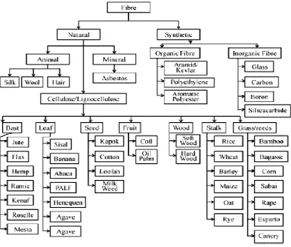
2.2 Classification of fibre 5
2.3 Composite categorization 9
2.4 Mercedes Benz automotive parts fabricated by natural fibres 10
2.5 Use of PMC in automotive industries 11
2.6 Stimulation of software measuring brake pad wear depth 14
2.7 Brake pad hardness test machine 17
2.8 TGA result of alkyl modified benzene phenolic resin 19
2.9 Multi criteria decision making tree 25
2.10 Flow chart of material selection for brake pad 28
3.1 Work flow of project 33
3.2 Normalization matrix method 38
viii
LIST OF ABBREVIATIONS
AHP Analytic Hierarchy Process
ASME American Society of Mechanical Engineers
COF Coefficient of Friction
CO2 Carbon Dioxide
DSC Differential Scanning Calorimetry
ELECTREE Elimination and Choice Expressing Reality
ENTROPY-PROMETHEE Entropy Fuzzy Preference Ranking Method for Enrichment Evaluation
FRP Fibre Reinforced Polymer
FRPC Fibre Reinforced Polymer Composite
FUZZY AHP Analytic Hierarchy Process Based On Fuzzy Scales
HRR Hardness Rockwell R
MADM Multi-Attribute Decision Making
MCDM Multi-Criteria Decision Making
MODM Multi-Objective Decision Making
NIS’ Nigerian Industrial Standard
NIS Negative Ideal Solution
PIS Positive Ideal Solution
PROMETHEE II Preference Ranking Organisation Method for Enrichment
PMC Polymer Matrix Composite
SAE Society of Automotive Engineers
SI International System
TGA Thermal Gravimetric Analysis
TOPSIS To Ideal Solution
VIKOR VIsekriterijumsko KOmpromisno Rangiranje
ix
LIST OF SYMBOL
𝐴𝑖 - Alternatives
𝐴′ - Best ranked
𝐴′′ - Second best ranked
𝐶𝑗 - Criterias
DQ - Decision of Majority
𝐹𝑓 - Force of friction
𝐹𝑛 - Normal force
𝑓𝑖𝑗 - Normalization matrix
𝑓𝑗∗ - Positive Ideal Solution
𝑓𝑗− - Negative Ideal Solution
HV - Hardness value
𝐿𝑝𝑖 - Metric equation
𝑚 - Number of alternatives
𝑛 - Number of criterias
𝑣 - Weight of strategy
𝑄𝑖 - VIKOR values
𝑆𝑖 - Distance rate of alternative to positive ideal solution
𝑆− - Maximum distance rate of alternative to positive ideal solution
𝑆∗ - Minimum distance rate of alternative to positive ideal solution
𝑅𝑖 - Distance rate of alternative to negative ideal solution
𝑅− - Maximum distance rate of alternative to negative ideal solution
𝑅∗ - Minimum distance rate of alternative to negative ideal solution
𝜇 - Coefficient of friction
𝑤𝑗 - Weight of attributes
𝑥𝑖𝑗 - Original value of 𝑖th alternatives and 𝑗th criterias
1 CHAPTER 1
INTRODUCTION
1.0 BACKGROUND
In this era, most of the people have their own transportations such as automobiles.
Most of the car manufacturers spend money and efforts to improve and further research on
their products in terms of performance, safety and comfort. When a person wants to purchase
an automobile, the first concern is the car’s safety. Therefore, the braking system is one of
the most crucial systems because it can protect and ensure the safety of passengers. Safety
of cars has the leading role in automotive industry than the performance of the cars,
(Anderson, 1980).
The brake is a device that stops motion. Energy conversion occurs when reducing
the speed of the car. A friction brake is to stop a moving vehicle by converting kinetic energy
into heat energy through fiction. Therefore, a braking system must also good in coefficient
of friction. However, there are two types of brakes such as drum brake or disc brake. The
drum brake is a brake that use brake shoes compress against the inner surface of a rotating
drum to cause friction. Meanwhile, disc brake stops the motion of car with the friction
produce by using a pair of brake pads against a rotating disc.
The brake pad is a part of the disc brakes. Brake pad converts the kinetic energy of
car to heat energy by friction. There are many types of brake pad such as metallic pad,
asbestos pad, ceramic pad and semi-metallic pad. Brake pad made up of the binder, filler,
2
high coefficient of friction, high thermal conductivity, low wear rate, optimum hardness and
good mechanical properties (Eriksson et al., 2002; Nagesh et al., 2014; Pohane et al., 2016).
Reinforcing fibre in brake pad is to provide mechanical strength to the friction
material. When mechanical stress and thermal stress occur, the binder will hold the
components of brake pad firmly preventing from falling apart. The filler is used to reduce
cost and improve the manufacturability of brake pad. Frictional additives are lubricant which
added to brake friction material used to ensure the frictional properties and control wear rate.
[image:16.595.176.427.273.394.2]
Figure 1.1: Enlarged isometric view of a used brake pad (Gachoki and Kathenya, 2006)
1.2 PROBLEM STATEMENT
Nowadays, many manufacturers focus on using material that requires low cost and
produces high-performance products. A disc brake pad usually made up of many materials.
The scientist and manufacturers have found out a way to achieve same performance of actual
disc brake pad by using natural fibre reinforced composite to replace the reinforcing fibre in
disc brake pad since the natural fibres is easily available, has lightweight criteria, low cost,
and comparable mechanical properties. The objective of this study is to select the suitable
natural fibres for fibre reinforced composites to apply in disc brake pad by using the VIKOR
method and comparing the mechanical properties with the standard brake pad material
(Nigerian Industrial Standard, 1997; SAE, 2001).
3 1.3 OBJECTIVES
The objectives of this project as follow:
i. To select the suitable natural fibre reinforced composite for disc brake pad using
VIKOR method.
ii. To compare the performance of the new natural fibre reinforced composite brake
pad against standard brake pad.
1.4 SCOPES OF PROJECT The scopes of this project are:
i. The part of the car being focused in this project is automotive disc brake pad.
ii. The material selections is focusing on natural fibre reinforced composite class to
replace reinforcing fibre in disc brake pad.
iii. Material selection of natural fibre was carried out by using VIKOR Method.
4 CHAPTER 2
LITERATURE REVIEW
2.1 INTRODUCTION
A literature review is a fundamental element in a research which provides a
description, summary, and critical evaluation of research problem by surveys books,
scholarly articles, and any other sources relevant to the area of research. Furthermore, the
literature review can be used to obtain information regarding general properties of natural
fibre, multi-criteria decision method procedure, mechanical properties and criteria of the
brake pad.
2.2 BRAKE PAD
The brake pad is a part of the brake system that made up by a combination of various
materials and the function is to decelerate or stop the vehicle. The materials selected for
brake system must consist following criteria: coefficient of friction, thermal conductivity,
wear, tensile strength and hardness. Figure 2.1 shows example of brake pad
[image:18.595.124.478.599.737.2]
5 2.3 NATURAL FIBRE
Natural fibre is defined as substances produced by using raw material obtained from
plants and animals to be spin into filament, thread and others such as woven and knitted.
Lately, the researchers found out that the natural fibres provide tremendous environmental
advantages such as worldwide availability, biodegradability, low pollutant emissions and
low greenhouse gas emissions (Faruk et al., 2012; John et al., 2008; Mohanty et al., 2005).
Natural fibres are easily available around the world furthermore the marketing price for
natural fibres are cheap. The natural fibre has moderate mechanical properties compared to
synthetic fibre but natural fibre has a higher moisture sensitivity (Sanjay et al., 2016). Figure
2.2 shows the classification of fibre into the natural fibre and synthetic fibre. Table 2.1 shows
[image:19.595.97.515.378.732.2]the comparison between natural fibres and synthetic fibres.
6
Table 2.1 Comparison of natural fibres and synthetic fibres in different properties
(Sanjay et al., 2016)
Aspect Property Natural fibres Synthetic fibres
Technical Mechanical properties Moderate High
Moisture sensitivity High Low
Thermal sensitivity High Low
Environmental Resource Infinite Limited
Production Low High
Recyclability Good Moderate
Natural fibre such as kenaf, hemp, flax, jute and sisal are selected as reinforcement
in automobile parts due to natural fibres are lightweight and low cost. Holbery and Houston
(2006) had studied about natural fibre reinforced polymer composites in an automotive
application, the study found out that the natural fibre composites with thermoplastic and
thermoset matrices have good physical and mechanical properties to fulfil the requirement
as a part of the material in car component. While in 2006, the European Union legislation
had been implemented for expedition of natural fibre reinforced plastic automotive insertion
and 85% of the car must reused or recycled in 2015 (Official Journal of the European
Communities, 2000). Thus, the implementation of natural fibre reinforced composite in
automotive component should be enhanced in worldwide. Table 2.2 shows the advantages
7
Table 2.2: Advantages and disadvantages of natural fibre (Alkbir et al. 2016)
Advantages Disadvantages
Low specific weight results in a higher
specific strength and stiffness than glass
Lower strength especially impact strength
Renewable resources, production process
need only little energy and CO2 emissions
Variable quality, affected by weather
condition
Production with minimum investment Poor moisture resistance, which causes
swelling of fibres
Thermal recycling is possible Price fluctuations depend on agriculture
policy
High electrical resistance Low durability
Good thermal and acoustic insulation
properties
Poor fire resistance
Biodegradable Poor fibre or matrix adhesion
The mechanical performance and properties of several natural fibres and synthetic
fibre in the automotive application was being reviewed (Koronis et al., 2013). Table 2.3
shows the mechanical and physical properties of natural fibres. Based on Table 2.3, the
pineapple fibre was the highest tensile strength range of 413 - 1627 MPa while the tensile
8
Table 2.3: Mechanical and Physical properties of natural fibres (Alkbir et al., 2016)
Fibres Tensile
Strength (MPa)
Young’s Modulus (GPa)
Elongation at break (%)
Density (g/m3)
Sisal 350-640 12.8-22 3-7 1.41-1.45
Oil palm 70.9-248 14-6.7 14-25 0.7-1.55
Bamboo 215-218 28-30 1.3 0.6-0.91
Banana 529-914 427-32 5-9 1.35
Coir 120-304 4-6 15-40 1.15-1.25
Cotton 287-800 5.5-12.6 3-10 1.51-1.6
Flax 345-1500 23.9-27.6 1.6-3.2 1.5
Hemp 690 60-70 1.6-4 1.4-1.5
Jute 393-780 13-30 1.9 1.3-1.45
Kenaf 284-1191 21-60 1.6-3.5 0.13-0.17
Pineapple 413-1627 60-82 1.07-2.4
Ramie 400-938 44-128 1.2-8 1-1.55
2.4 NATURAL FIBRE REINFORCEMENT COMPOSITE
The term “reinforcement” in a composite material is fundamentally one of increasing
the mechanical properties of the neat resin system. Meanwhile, the term “composite” means
a combination structural component produced by a physical combination of two or more
materials. In addition, the term “composite” in material science provide meaning that a
material is made up of a matrix containing reinforcing agents. Fibre reinforced material is
divided into the continuous phase and discontinuous phase. The continuous phase is known
as matrix while discontinuous phase is known as fibre. The composite material consists of
one or more discontinuous phase that is embedded in continuous phase to become
reinforcing material that has stronger and hard material characterisation (Chandramohan and
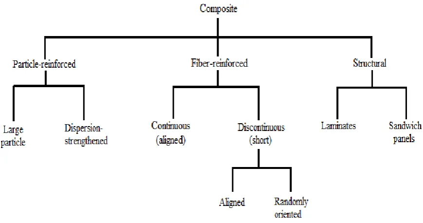
Marimuthu, 2011). Figure 2.3 shows the categorization of the composite into three main
9
Figure 2.3: Composite categorization (Callister, 2006)
In automotive industries, natural fibre reinforced composites, deriving from
renewable resources, have therefore attracted extensive attention as promising alternatives
to replace traditional fibre (Joshi et al., 2004; Koronis et al., 2012; Puglia et al., 2005).
Natural fibre reinforced polymer composite such as jute, flax, hemp, sisal and others have
already been embraced by European automobile manufacturers for manufacturing
automotive interior and exterior parts like door panels, package trays, dashboards,
headliners, seat backs and trunk liners (Ahmad et al., 2015). According to Monteiro et al.
(2010) on his previous studies about natural lignocellulosic fibres. Figure 2.4 shows the
Mercedes Benz Sedan automotive parts had done some changes such as natural
lignocellulosic reinforcement polymer composite are replacing the synthetic fibre in
automotive parts. The results show the smallest diameter of lignocellulose fibre obtained
10
Figure 2.4: Mercedes Benz automotive parts fabricated by natural fibres
(Monteiro et al., 2010)
2.5 POLYMER MATRIX COMPOSITES
Polymer matrix composites (PMCs) is a class which under of fibre reinforced
composite (FRC). Polymer matrix composites are made up of polymer resin as matrix and
fibres as the reinforcement medium. Those polymer matrix composites combine with
reinforcement type become fibre reinforced polymer composites (FRPC). Fibre reinforced
polymer composites (FRPC) are composite materials are made up by combination of
polymer matrix with high strength fibres such as aramid, glass and carbon. Recently, the
scientist and engineers had researched and utilizing all plant fibres to produce good quality
fibre reinforced polymer composites for various field of industry. This research brings a huge
opportunity for plant fibres to develop a new composite material. Natural fibre-reinforced
polymer composites improve the environmental quality since most of the plant fibres such
as kenaf, sisal and jute fibres are biodegradable. Importantly, the plant fibres can become
reinforcement for composite material that provides mechanical strength and able to
substitute glass, carbon, and aramid in fibre reinforced polymer composite.
11
the military for radar aircraft (Lubin, 1988; Piggot, 1980). Since natural fibre reinforced
polymer composites is low cost, low density, good mechanical properties and simple
processing advantages, the research development progress had become faster than before
(Satyanarayana et al., 1990).
The advantages of natural fibre reinforced composite are:
The natural fibres are renewable, low cost, biodegradable and non-abrasive to
processing equipment.
The production of natural fibre reinforced composites give lower environment
pollution.
The natural fibre reinforced composites are lightweight and capable to be used in
automotive part components.
Show good mechanical properties such as good acoustic and thermal insulating
properties
The following Figure 2.5 shows the usage of polymer matrix composite in automotive
[image:25.595.141.471.491.731.2]industry.
12 2.6 SYNTHETIC FIBRE
Synthetic fibres are defined as man-made fibres from chemicals. Synthetic fibres
mostly based on polymers, are stronger than natural and regenerated fibres and can be
modified to have different performance characteristics. Table 2.4 shows the advantages and
[image:26.595.81.524.263.489.2]disadvantages of synthetic fibres.
Table 2.4 Advantages and disadvantages of synthetic fibre (Anonymous, n.d.).
Advantages Disadvantages
Stronger strength Produced using fossil fuels (petroleum)
Stronger durability Use chemical which could harm humans
and non-environment friendly
Low expensive production Melting when at hot temperature
Weak water absorption ( this is an advantage
or disadvantage depending on the
application)
Non-biodegradable
2.7 CRITERIA FOR BRAKE PAD 2.7.1 COEFFICIENT OF FRICTION
The coefficient of friction is the value of the force of friction between two objects or
more objects are involved. The SI unit for the coefficient of friction is μ. The following Eq
2.1 shows the coefficient of friction is being used in the calculation of frictional force
(Burwell and Rabinowicz, 1953):
𝐹𝑓 = 𝜇 . 𝐹𝑛 (2.1)
13
One of the most important criteria of brake pad is the coefficient of friction. The
friction of coefficients for brake material pairs should be in the range from 0.07 to 0.7.
However, most of the vehicles operate within the range from 0.3 to 0.6 in friction coefficient
(Anderson, 1980). The coefficient of friction should be maintained at a stable level
irrespective of temperature, humidity, the age of the pads, the degree of wear, corrosion, the
presence of dirt and water spraying from the road (Eriksson, 2001; Mutlu, 2006).
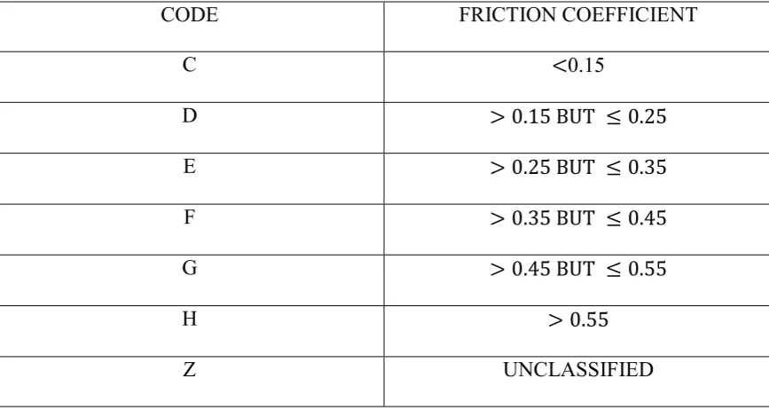
The society of automotive engineers (SAE) developed a Friction Identification
System for Brake Linings and Brake Blocks (SAE Recommended Practice SAE J866a).
Edge codes are used to show the coefficient of friction of brake linings and brake blocks.
[image:27.595.88.522.429.660.2]Table 2.5 shows the following list of codes and associated friction coefficients.
Table 2.5: Value of friction of coefficient and codes SAE Recommended Practice J866a
(Blau et al., 2001)
CODE FRICTION COEFFICIENT
C <0.15
D > 0.15 BUT ≤ 0.25
E > 0.25 BUT ≤ 0.35
F > 0.35 BUT ≤ 0.45
G > 0.45 BUT ≤ 0.55
H > 0.55
14 2.7.2 WEAR
Wear in automotive industry meaning as material removal from a surface due to
friction with another surface. However, wear rate is known as wear volume per unit distance.
Wear rate usually change in the range of 10−15 to 10−1 𝑚𝑚3/𝑁𝑚 but it is based on several
circumstances such as operating conditions and material selections (Kato and Adachi, 2001).
Meanwhile, the term “wear rate” in brake pad mean thickness loss of brake pad after
the braking performance. In SAE J661 test standard, there are 7 tests to test the wear rate
and coefficient rate of the brake pad. According to Incesu et al., (2013) previous studies
about the design of composite brake pads for the metro with a statistical approach, the brake
pad is proved are better to have lower wear rate which is lower than 10%. The Table 2.6
show the commercial brake pads and a testing sample of brake pad undergo SAE J661
Testing Standard. Figure 2.6 shows the simulation software used to measure brake pad wear
[image:28.595.205.406.433.587.2]depth.
Figure 2.6: Simulation of software measuring brake pad wear depth from
15
Table 2.6: SAE J661 Testing Standard on brake pad (Incesu et al., 2013)
2.7.3 TENSILE STRENGTH
Tensile strength is defined as ability or strength of the material to withstand a pulling
force. But in term “tensile strength of material” describes the maximum amount of tensile
stress that material can endure before breaking or permanent deformation. However, there
are three types of tensile strength such as yield strength, ultimate strength and breaking
16
selection. By referring to Dow (1985), the standard tensile strength of brake pad friction
material should not be less than 20 MPa (Nigerian Industrial Standard, 1997).
2.7.4 THERMAL CONDUCTIVITY
Thermal conductivity is defined as the property of a material to conduct heat. For
example, high thermal conductivity material is commonly used for heat dissipation while
low thermal conductivity material used for heat insulation.
Thermal conductivity is one of the main criteria in brake friction material. During
braking process, both of the disc brake and brake pad had absorbed a large amount of heat
released in a few seconds (Travaglia and Lopes, 2014). The heat absorbed by both disc brake
and brake pad must dissipate as fast as possible to prevent malfunction on the operation of
braking system (Day and Newcomb. 1984). There are some possible problems will occur
such as thermal cracks, premature wear, brake fade and thermally during excited vibration
if the temperature of braking process is high (Lee, 1999). The standard thermal conductivity
of a brake friction material must be in the range of 0.47 to 0.804 W/mK (Dagwa and
Ibhadode, 2015).
2.7.5 HARDNESS
Hardness is defined as the measurement of resistant to solid before changing into any
shape when a compressive force is applied. The common materials such as ceramic, metal,
and concrete undergo hardness test by using Vickers hardness tester.
Brake pad hardness used to describe friction material durability. According to Unaldi
and Kus (2017), the density and hardness properties were affected by alumina component of
17
Test (HB) and using hardness test machine (DIGIROCK-RBOV). An example of brake pad
[image:31.595.224.385.125.301.2]hardness test machine is shown in Figure 2.7.
Figure 2.7: Brake Pad Hardness Test Machine (www.bullbrakes.com)
2.8 COMPONENT OF BRAKE PAD 2.8.1 BINDER
Binder is a type of thermoresin used to hold all other components together in order
to form a thermally stable matrix (Feist, 2013; Weintraub, 1998). Phenolic resin is one of
the common material which selected as a binder in the brake pad. There are two types of
phenolic resin such as alkyl benzene modified phenolic resin and actual phenolic resin.
Phenolic is a type of thermoset polymer form by a condensation reaction between phenol
and formaldehyde and is able to act as a matrix for binding agent together different
substances (Salamone, 1998). Alkyl benzene modified phenolic matrix resin was
synthesized from SI chemicals and it was characterized by curing temperature and thermal
degradation temperature by standard Differential Scanning Calorimetry (DSC) and Thermos
Gravimetric Analysis (TGA) studies.
Balaji and Kalaichelvan, (2013) had studied the thermal and fade aspects of a
non-asbestos semi-metallic brake pad formulation with two different resins. Table 2.7 shows the
18
modified phenolic resin (NA-02) has higher coefficient friction and more stable to thermal
[image:32.595.77.525.181.466.2]analysis compare to the phenolic resin (NA-01).
Table 2.7: SAE J661a Frictional Response of Friction Composites (Balaji and
Kalaichelvan, 2013)
Properties NA-01 NA-02
Hot friction or Fade (𝜇) 0.362 0.465
Normal or recovery (𝜇) 0.465 0.472
First Fade by Calculation (%) 23.02 12.367
First Recovery by Calculation (%) 90.33 103.83
Second Fade by Calculation (%) 4.396 19.4
Second Recovery by Calculation (%) 87 93.3
Max (𝜇) 0.474 0.520
Min (𝜇) 0.310 0.411
Wear loss by wt (%) 5.9 4.7
A research regarding optimization of alkyl benzene modified phenolic resin in a
friction composite to the effect on thermal stability, friction stability and wear performance
conducted by Balaji, 2014. The research outcome shown the amount of resin in brake pad
can affect the integrity of brake pad and other important properties. Furthermore, alkyl
benzene modified phenolic resin can be conducted for TGA test. This analysis is to show the
thermal stability of materials. Figure 2.8 shows the TGA result of alkyl benzene modified
19
[image:33.595.137.478.70.310.2]
Figure 2.8: TGA of alkyl benzene modified phenolic resin
(http://shodhganga.inflibnet.ac.in/bitstream)
2.8.2 FILLER
The reasons for filler being used in brake pad are to reduce the cost and improve the
manufacturability of brake pad. There are two types fillers such as inorganic filler and an
organic filler. The materials which consider as inorganic fillers are such as barium sulphate,
mica, vermiculite and calcium carbonate. The inorganic fillers have a high melting point.
For instance, barium sulphate is commonly used as fillers since it is chemically inert and has
a melting point of 1350 ℃ (Lide and Kehiaian, 1994). Barium sulphate imparts heat stability
to the brake friction material, at the same time aiding the friction characteristics of the brake
friction material (Komori et al., 1990). The behaviours, advantages and disadvantages of
20
Table 2.8: Description of inorganic fillers (Chan and Stachowiak, 2004)
Filler Description
Barium Sulphate Imparts heat stability to friction material
Calcium Carbonate Imparts heat stability to friction material characteristic
Mica Suppresses low frequency brake noise, but cause interlayer split
Vermiculite Suppresses low frequency brake noise, and low heat resistance
Alkali metal titanates Lead to stability of friction coefficient
Molybdenum trioxide Avoid thermal fade and cracking of friction lining
Cashew dust Suppresses brake noise, but does not handle well to friction
material
Rubber dust Suppresses brake noise, but does not handle well to friction
material
Typical organic fillers such as cashew dust and rubber dust. Both have similar
properties in that they are usually incorporated into brake pads for the purpose of reducing
brake noises due to their superior viscoelastic characteristics (Kamioka et al., 1995). Cashew
dust is easily fall off from friction surface during friction and caused crack after leaving
behind large pores (Kinouchi et al., 2002). The advantages of cashew or rubber particles are:
Low thermal conductivity that prevents heat from transmitting back to brake
friction material. (Nakagawa, 2001)
Reduce fluctuations in friction coefficient at elevated temperatures. (Jang and
Kim, 2000)
Kim et al. (2004) had studied the effect of potassium titanate and barium sulphate on
21
barium sulphate filled friction composites remain higher density and hardness meanwhile
potassium titanate filled friction composite remain maximum void content.
2.8.3 ABRASIVE
Abrasives increase the coefficient of friction during friction and wear rate of
counterface material. Typical abrasive include iron oxide, aluminium oxide, quartz, silica
and zirconium silicate. Most of the abrasives are hard particles because it must be hard
enough to at least abrade the counter friction material which is typically cast iron.
Yiannoulakis, (2015) on his previous studies regarding friction material in brake
lining, the magnesium oxide can select as one of brake friction material due to magnesium
oxide able to increase the thermal stability of phenolic resin and resistance between friction
material furthermore capable to suppress low-frequency noise during braking.
2.8.4 FRICTIONAL ADDITIVES
The main purpose of frictional additives being added to brake friction materials is
to modify the friction coefficient and wear rate (Pohane et al., 2016). The frictional additives
are solid lubricants like graphite and metal sulphides that is utilized to ensure stable frictional
properties and control wear primarily at elevated temperatures (Feist, 2013).
Graphite had played the role of friction modifier since 2003 in brake pad material.
The graphite can exist in flake or powder form. However, graphite in flake form improved
lubrication properties (Takahasi et al. 1999), meanwhile graphite in powder form capable to
dissipate heat generated during braking more effectively (Booher, 1992). Table 2.9 shows
22
Table 2.9: Frictional additives of brake pad material (Gachoki and Kathenya. 2006)
Frictional additives Description
Graphite Widely used lubricant, usually in natural or synthetic forms.
Metal sulphides Good lubricating properties, lower conductivity than graphite
Metal oxides or
silicates
Abrasives with hardness ranging from 500HV (quartz) to 1750HV
(aluminium oxide): example include zirconium silicate and quartz.
Thiyagarajan et al. (2003) had studied the thermomechanical properties of carbon
fibres and graphite powder reinforced asbestos-free brake pad composite material. The
results show that graphite powder increased the thermal conductivity of the composite brake
pad material. The graphite powder also good in controlling the hardness of brake pad to the
desired level.
2.8.5 REINFORCING FIBER
The purpose of reinforcing fibre in brake pad is to provide mechanical strength to
the friction material. Nowadays, reinforcing fibres are commonly used in automotive
industry in order to replace asbestos fibres. In the late 1980s, scientist found out that asbestos
is a carcinogen, therefore, manufacturers starting to look for suitable alternatives. Table 2.10
23
Table 2.10: Advantages and Disadvantages of Reinforcing Fibre (Gachoki and Kathenya,
2006)
Components Advantages Disadvantages
Glass Sufficient thermal resilience (high melting point of 1430℃, but start soften at around 600℃)
Brittle
Metallic Thermally resilient steel and copper have melting points higher than 1000℃
Large amounts will cause rotor wear and corrode Aramid Good stiffness in weight ratio,
excellent thermal resilience, good wear resistance
Soft cannot be used without other fibres
Potassium titanate Thermally resilient (high melting point of around 1371℃) and good wear resistance.
Health hazard
Sepiolite Thermally resilient (high melting point of around 1550℃); able to absorb traces of fluid
Potential health hazard
Ceramic Thermally resilient (high melting point of around 1700-2040℃); good stiff-weight ratio
Brittle
According to Eriksson et al. (2002) in his previous studies regarding on the nature
of tribological contact in automotive brakes, the studies had shown that the braking load is
carried by tiny plateaus that rise above the lowlands of friction material. The tiny plateaus
are formed when the reinforced fibres surrounded by the softer compact components. The
friction material should use a mixture of different types of reinforcing fibre with
24
2.9 RESEARCHES ON BRAKE PAD
There are some researches regarding brake pad had been carried out in these past few
years. Most of them share the common idea such as using natural fibre as alternative for
asbestos fibre. According to Ghazali et al. (2012) in his previous studies on mechanical
properties and wear behaviour of brake pad produced from palm slag, the studies had shown
that the hardness, compressive strength and wear behaviour of palm slag had potential to
replace as filler in asbestos free brake pad. Besides that, Ghazali et al. (2013) also conducted
a studies about mechanical properties and morphology of palm slag, calcium carbonate and
dolomite filler in brake pad composites. The research result shown that combination of palm
slag and calcium carbonate inside brake pad composite provide better wear properties than
dolomite and capable compare to conventional asbestos based brake pad.
Other than that, Idris et al. (2013) had carried out a research about eco-friendly
asbestos free brake pad using banana peels. The result shown that the mechanical properties
such as compressive strength, hardness and specific gravity of the produced samples such as
uncarbonized banana peels and carbonized banana peels have improved with increased in
weight fraction of resin addition. Thus, banana peels particles able to replace asbestos
effectively in brake pad composite.
Besides that, according to Ikpambese et al. (2014) research about evaluation of palm
kernel fibers (PFKs) for production of asbestos-free automotive brake pads, the research
used epoxy resin as binder and result show that it is compatible to commercial asbestos.
Therefore, palm kernel fibre capable to replace asbestos brake pad.
2.10 MULTI CRITERIA DECISION MAKING (MCDM)
The material selection is one of the important process in engineering design to fulfil
25
economic, aesthetic, personality and ecological dimensions. As an engineer, the physical,
mechanical, and thermal properties of material should be checked thoroughly before proceed
to selection process. Filter and select the materials that meet product criteria and
performance meanwhile try to seek for alternative material can replace the current material
used. There are many methods can be used for material selection either using software or
non-software. The selection of material and alternative material process should carry out in
proper approach.
Multi-criteria decision-making (MCDM) methods had many different approaches.
MCDM methods can classify into two categories: discrete MCDM or discrete Multi-attribute
Decision Making Method (MADM) and continuous Multi-objective Decision-Making
Method (MODM) (Chauhan and Vaish, 2012; Zavadskas et al., 2014). Nowadays, a lot of
information, researches and publications have been published regarding MCDM methods
and its application in different fields. Material selection using MCDM had been strongly
proposed by some authors such as (Liu et al., 2013; Çalışkan et al., 2013; Khorshidi and
Hassani, 2013). The Figure 2.9 shows the sequence of MCDM.
[image:39.595.185.445.515.654.2]
Figure 2.9: Multi-Criteria Decision Making (MCDM) Tree
MCDM method can also be used for material selection in engineering design
industry. For example, Kumar and Ray (2014) had used multi-criteria decision making in
26
used to select suitable alternative materials such as weighted sum model (WSM), weighted
product model (WPM), analytic hierarchy process (AHP), elimination and choice expressing
reality (ELECTRE), technique for order of preference by similarity to ideal solution
(TOPSIS), analytic hierarchy process based on fuzzy scales (FUZZY AHP) and VIKOR
method.
Recently, MCDM starting become a popular method for material selection in the
automotive industry. Maleque et al. (2010) used material selection method to select the most
suitable material in the design of automotive disc brake. The disc brake is one of the most
important component in car safety because it undergo a few energy transformation process
before the car stopped. In this research, digital logic method was used to find weighting
factors and the result of each material proposed were ranked and compared.
The researcher Chirag et al. (2016) had used entropy fuzzy preference ranking
method for enrichment evaluation (Entropy-PROMETHEE) based decision making
methodology to carry out material selection and based on tribological properties of brake
friction material. The material selection for brake friction material is being accounted into
performance defining criterions. The data of material for performance defining criterions is
simplified into a table. In this research, the entropy is used for the estimation of weight for
each criterion, while PROMETHEE II is used to rank the alternatives.
Dante et al. (2000) had carried out a lot of experimental technique using Taguchi
design concept for friction material formulation. The result showed that the advantages of
Taguchi design technique had saved time in the progress of choosing suitable ingredients for
ideal material development. Similarly, performance and ranking system can occupied on
brake friction material. Satapathy et al. (2004) had studied about the performance of friction
materials based on variation in nature of organic fibres part I, fade and recovery behaviour.
27
using balancing and ranking method. While the author had been used the combination of
AHP-TOPSIS for friction material selection.
Besides, many researches had been done on material selection of natural fibre,
hybrid fibre, natural fibre reinforced composite in automotive industry. A few years ago,
Mansor et al. (2013) had studied regarding hybrid natural and glass fibres reinforced polymer
composites material selection using analytical hierarchy process for automotive brake lever
design. The author had utilized the AHP method for material selection of natural fibre that
need to be hybridized with glass fibre reinforced polymer composite. The result from
research showed the kenaf bast fibre displayed the highest scores and best candidate to
formulate the hybrid polymer composites in automotive component construction.
2.10.1 VIKOR METHOD
The VIKOR algorithm was proposed by (Opricovic, 1998), an MCDM method
commonly used for a complex system based on ideal point method. The objective of VIKOR
is determining positive ideal solution and negative ideal solution in the first place. The
positive ideal solution is the optimum value of alternatives under criteria, and the negative
ideal solution is the worst value of alternatives under criteria. Lastly, proceed to the priority
arrangement of the schemes based on the proximity of the alternatives assessed value to the
ideal schemes. The multi-criteria measure for compromise ranking is developed from the
𝐿𝑝-metric used as an aggregating function in a compromise programming method shown in
Eq. (2.1) (Yu, 1973; Zeleny, 1998).
𝐿𝑝𝑖= { ∑𝑛𝑗=1[ 𝑤𝑗 (𝑓𝑗∗− 𝑓𝑖𝑗) / ( 𝑓𝑗∗− 𝑓𝑗−)]𝑝}1 𝑝⁄ (2.1)
Where 1≤ 𝑝 ≤ +∞ ; 𝑖 = 1,2, … 𝐼 . 𝐼 respects the number of alternatives. Each
28
; the measure 𝐿𝑝𝑖 means the distance between alternative 𝑎𝑖 and positive ideal solution.
Ranking by VIKOR may produce different values of criteria weights. Criteria weights
greatly affect compromise solution. The VIKOR method determines the weights stability
intervals, using the methodology proposed by (Opricovic, 1998). He compromise solution
obtained with initial weights 𝑤𝑖 , 𝑖 = 1,2,… 𝑛 will be replaced if the value of a weight isn’t
within the stability interval.
2.11 MATERIAL SELECTION
The selection of material for brake pad is not an easy task because the need to
undergo a different process by according to the stages. The Figure 2.10 shows the flow chart
of material selection for brake pad material. VIKOR method is used for material selection in
brake pad friction material. The materials involved in material selection are natural fibre
29
[image:43.595.220.401.98.496.2]
Figure 2.10: Flow chart of material selection for brake pad
2.11.1 POTENTIAL MATERIAL TO REPLACE ASBESTOS FIBRE
The traditional reinforcing fibre for automotive brake pad is asbestos fibre. Due to
asbestos fibre is harmful to human and environment, therefore research on potential
alternative material to replace asbestos fibre is carried out. The following describes the
potential alternative material can be used for brake pad. Brake Pad Criteria
General Material Performance Requirement
Initial Screening of Candidate Material
Material Selection Using VIKOR Method
Evaluation and Ranking Each Alternative
Compare Against Standard Brake Pad
30 i. Palm kernel fibre
Palm kernel fibre is easily available, low cost, and have quite good mechanical
properties such as coefficient of friction, hardness and others. Ikpambese et al., (2014)
prepared brake pad material using natural fibre called palm kernel fibres (PKFs) for its
eco-friendly nature with CaCO3, graphite and Al2O3 as other constituents. Epoxy resin is used as
a binder. The composition of 40% epoxy-resin, 10% palm wastes, 6% Al2O3, 29% graphite,
and 15% calcium carbonate gave better properties than other composition.
ii. Date palm fibre
Advantages of date palm fibre was low cost, low density, chemical resistance, high
strength to weight ratio and good relative mechanical properties (Alajmi et al., 2015).
Moreover, the date palm trees are renewable source of fibres.
iii. Sisal fibre
Sisal fibre is a type of natural fibre made up of cellulose structure. A piece of sisal
fibre is not a single filament like carbon or glass fibre but a bundle of cellular aggregate
consisting of more than 100 irregular hexagonal hollow ultimate cells (Barkakaty, 1976). A
few research had been conducted on sisal fibre reinforced composites because sisal fibre is
environmentally friendly, cheap, lightweight and good mechanical performance (Xin et al.,
2007).
iv. Bamboo fibre
The bamboo fibre had become one of choice for composite material due to their
31
glass fibres (Ma et al., 2012). Bamboo fibre also biodegradable and environmental friendly
which does not cause harm to human health.
Based on the properties, potential candidate materials for automotive brake pad were
selected as:
Sisal fibre reinforced resin brake composites (15 wt% resin , 20 wt% fibre)
Date palm fibre reinforced epoxy composites (100 wt% epoxy, 35 wt% fibre)
Bamboo fibre reinforced composites (3 wt% fibre)
32 CHAPTER 3
METHODOLOGY
3.1 INTRODUCTION
This chapter describes the methodology of material selection of natural fibre which
can be become either natural fibre reinforced composite or natural fibre reinforced polymer
composite for the brake pad. The tools and methods used in this project is VIKOR method,
table of selection and comparative approach. All material selection are selected after
searching from various sources and comparing the material properties against the
requirement of the brake pad. The VIKOR method is used to calculate and rank the best
material by using the data of materials provided. Table of selection is used to identifying the
best material as final material in this studies. While, the comparative approach is to compare
to final material against standard criteria value, in order to determine whether final material
fulfil the requirement of standard brake pad criteria. Thus, Figure 3.1 shows the workflow
33
Figure 3.1: Work flow of the project START
NATURAL FIBRE
NATURAL FIBRE REINFORCED COMPOSITE
SCREENING MATERIALS USING CONSTRAINT 1) Mechanical Properties of material
- Coefficient of friction of material - Wear rate of material
- Tensile strength of material - Hardness of material
2) Thermal Properties of material - Thermal conductivity of material 3) Biodegradable and widely available
4) Eliminate the materials that does not meet the objective requirement and select another material from natural fiber
BRAKE PAD CRITERIA
VIKOR METHOD
TABLE OF SELECTION
COMPARATIVE APPROACH - Compare SAE COF - Compare Thermal
Conductivity - Compare Wear rate - Compare Tensile strength - Compare Hardness
INTERPRET RESULT
[image:47.595.218.391.435.722.2]34 3.2 WORKING STEPS OF VIKOR METHOD
1) Calculate the normalized value
For example, there are m alternatives and n attributes. The different I alternatives are
denoted as 𝑥𝑖. The rating of the 𝑗th aspect is denoted as 𝑥𝑖𝑗 and this is for alternatives 𝑥𝑗.
In progress to obtain normalized value, the following Eq. (3.1) can be used by assuming that
𝑥𝑖𝑗 is the original value of 𝑖th option and 𝑗th dimension.
𝑓𝑖𝑗 = 𝑥𝑖𝑗
√∑ 𝑥2 𝑖𝑗 𝑛
𝑗=1 , 𝑖 = 1,2, … ; 𝑚′𝑗 = 1,2, … , 𝑛
⁄ (3.1)
2) Determine the best and worst values
Calculate each criterion’s value 𝑓𝑗∗ and negative ideal solution’s value 𝑓𝑗− for
𝑗 = 1,2, …n by using Eq. (3.2) and Eq. (3.3) respectively.
𝑓𝑗∗ = max𝑓
𝑖𝑗, 𝑖 = 1,2, … , 𝑚 (3.2)
𝑓𝑗− = min 𝑓
𝑖𝑗, 𝑖 = 1,2, … , 𝑚
3) Determine the weights of attributes
The 𝑤𝑗 are the weights of criteria, to express their relative importance.
4) Compute the distance of alternatives to ideal solution
This step is taken for calculating the distance from each alternative to positive ideal
solution and sum up all value to obtain final value by referring to Eq. (3.4) and Eq. (3.5).
35
𝑅𝑖 = max𝑗 [ 𝑤𝑗(𝑓𝑗∗− 𝑓𝑖𝑗)/(𝑓𝑗∗− 𝑓𝑗−)] (3.5)
Where 𝑆𝑖 represent the distance rate of 𝑖th alternative to the positive ideal solution
(best combination), 𝑅𝑖 represents the distance rate of the 𝑖th alternative to the negative ideal
solution (worst combination). The best ranking is based on 𝑆𝑖 values and worst ranking is
based on 𝑅𝑖 values.
5) Calculate the VIKOR values 𝑄𝑖 for 𝑖 = 1,2, … , 𝑚. The Eq. (3.6) for 𝑄𝑖 is :
𝑄𝑖 = 𝑣 [𝑆𝑖−𝑆∗
𝑆−−𝑆∗] + (1 − 𝑣) [
𝑅𝑖−𝑅∗
𝑅−−𝑅∗] (3.6)
Where 𝑣 is the weight of strategy of the majority of criteria. If 𝑣 value is more
than 0.5, then index 𝑄𝑖 will shift to majority agreement. If 𝑣 value is lesser than 0.5, then
index 𝑄𝑖 will shift to majority disagreement. Therefore, in general 𝑣 = 0.5, whereas others
represent:
𝑆− = max
𝑖 𝑆𝑖 , 𝑆
∗ = min 𝑖 𝑆𝑖
𝑅− = max
𝑖 𝑅𝑖 , 𝑅
∗ = min 𝑖 𝑅𝑖
6) Rank the alternatives by 𝑄𝑖 values
After insert and calculate all values in each equation, the final value 𝑄𝑖 can obtained
to rank the alternatives and make decision.
7) Sorting the rank of alternative by 𝑆𝑖, 𝑅𝑖 and 𝑄𝑖
36
rank of alternative in ascending order into a table before proceed to checking VIKOR
condition 1 and 2.
3.3 VIKOR METHOD CONDITIONS
There are two conditions must be done after using VIKOR method.
Condition 1: Acceptable advantage Eq. (3.7):
𝑄(𝐴") − 𝑄(𝐴′) ≥ 𝐷𝑄 (3.7)
Where 𝐴" is the alternative with ranked second position in the ranking list by 𝑄;
𝐷𝑄 = 1, (𝑚 − 1); 𝑚 is the number of alternatives
Condition 2: Acceptable Stability in decision making:
Alternative 𝐴′ must also be the best ranked by 𝑆 or 𝑅. This compromise solution is
stable within a decision making process, which could be “voting of majority rule” (when
The (𝑣 > 0.5 is needed), or “by consensus” if 𝑣 ≈ 0.5, or “with veto” (𝑣 < 0.5). The 𝑣 is
the weight of the decision making strategy.
If one of the conditions is not satisfied, then a set of compromise solutions is
proposed, which consists of:
Alternatives 𝐴′ and 𝐴" if it is condition 2 are not satisfied
Alternatives 𝐴′, 𝐴" ,..., 𝐴(𝑚) if condition 1 are not satisfied; 𝐴(𝑚) is
37
3.4 MATERIAL SELECTION USING VIKOR METHOD
In this study, the best material of natural fibre for brake pad is calculated and ranked
from VIKOR method. The objective of this material selection is to select excellent
mechanical properties, biodegradable, low cost and widely available material such as natural
fibre reinforced polymer composite as one of the reinforced fibre in the brake pad. In order
to eliminate the material that unable to fulfil the selection requirement, the general properties,
mechanical properties and thermal properties are used in the material screening process. The
properties that involve for VIKOR method is the coefficient of friction, thermal conductivity
(k), wear, tensile strength (MPa) and hardness.
The Eq. (3.1) is used for a normalized matrix which is the first step in VIKOR method.
The properties of brake pad material for VIKOR method are used as 𝐶𝑗 represent 𝑗𝑡ℎ
attribute, while the candidates of material is used for 𝐴𝑖 represent 𝑖𝑡ℎ alternative in Eq. (3.1).
The result for Eq. (3.1) will be arranged in this form as shown in Figure 3.2. The Eq. (3.2)
and Eq. (3.3) are used to determine the maximum and minimum value of 𝑗𝑡ℎ attributes. The
weight of attribute is based on how important of the attribute from journal. Eq. (3.4) and Eq.
(3.5) are used to calculate distance of each alternative to positive ideal solution. Good
ranking will write on 𝑆𝑖 values while worst ranking will write on 𝑅𝑖 values. Eq. (3.6) is used
for calculate 𝑄𝑖, VIKOR value of brake pad and finally rank the alternatives based on
VIKOR value. After ranking, two conditions are required to be carried out in Eq. (3.7) and
Eq. (3.8).
𝑓𝑖𝑗 = 𝑥𝑖𝑗
√∑ 𝑥2 𝑖𝑗 𝑛
𝑗=1 , 𝑖 = 1,2, … ; 𝑚′𝑗 = 1,2, … , 𝑛
⁄
𝑓𝑗∗ = max𝑓
38
𝑓𝑗− = min 𝑓
𝑖𝑗, 𝑖 = 1,2, … , 𝑚 (3.3)
𝑆𝑖 = ∑𝑛 𝑤𝑗
𝑗=1 (𝑓𝑗∗− 𝑓𝑖𝑗)/(𝑓𝑗∗− 𝑓𝑗−) (3.4)
𝑅𝑖 = max𝑗 [ 𝑤𝑗(𝑓𝑗∗− 𝑓𝑖𝑗)/(𝑓𝑗∗− 𝑓𝑗−)] (3.5)
𝑄𝑖 = 𝑣 [𝑆𝑖−𝑆
∗
𝑆−−𝑆∗] + (1 − 𝑣) [
𝑅𝑖−𝑅∗
𝑅−−𝑅∗] (3.6)
𝑄(𝐴") − 𝑄(𝐴′) ≥ 𝐷𝑄 (3.7)
39
3.5 MATERIAL SELECTION FOR NATURAL FIBRE
The material selection for natural fibre before proceeding to VIKOR method are
based on a few conditions. Stage 1 is a limitation stage for natural fibre material candidates
to remove the materials from the list that do not fulfil the requirement of brake friction
material. The materials are arranged by according to the characteristic of natural fibre such
as biodegradable and widely available in the world. The materials contain good mechanical
properties that can improve mechanical strength and performance of a brake pad. Stage 2 is
searching and screening the materials of natural fibre perform high coefficient of friction.
Stage 3 is finding and choosing the materials of natural fibre to contain low thermal
conductivity. Stage 4 is the material candidates must have high tensile strength. Stage 5 is
the material candidates must have moderate hardness. Stage 6 is about the material
candidates should have low wear rate. Combine the result from all stages into a table to
proceed for VIKOR method and remove all material candidates which do not fulfil the
40 3.6 TABLE OF SELECTION
All the result calculated from VIKOR method is summarised into a table. Based on
the result, the ranking of the material candidate is determined. Table 3.1 shows the template
[image:54.595.112.494.230.504.2]table for VIKOR method result.
Table 3.1: Sample template for VIKOR method result (Opricovic, 1998)
3.7 COMPARATIVE APPROACH
After the best ranking alternative is obtained, the attribute of the material candidate
is used to compare against standard brake pad material attribute. The data for standard brake
pad attribute is obtained from Society from Automotive Engineers (SAE international) and
Nigerian Industrial Standard (NIS).
Attributes 𝐶𝑗=1 𝐶𝑗=2 𝐶𝑗=3 𝐶𝑗=4 𝐶𝑗=𝑛
Weights, 𝑤𝑗
Alternatives
𝐴𝑖=1
𝐴𝑖=2
𝐴𝑖=3
𝐴𝑖=4
𝐴𝑖=𝑚
𝑓𝑗∗
41 CHAPTER 4
RESULT AND DISCUSSION
4.1 Material Selection Table
Initially, the study on the properties of natural fibre and criteria of brake pad was
continuously carried out for a few weeks. After gathering and reviewing of important
properties of natural fibre in an automotive application, the initial material candidate of
natural fibre for brake pad friction material is palm kernel fibre, date palm fibre, sisal fibre
and bamboo fibre. However, most of the material candidates are natural fibre reinforced
composite and natural fibre reinforced polymer composite. All of the material candidates are
biodegradable, environmentally friendly, and easily available. The properties of material
candidates are summarised in Table 4.1 before proceeding to VIKOR method. The properties
of material candidates used in Table 4.1.
[image:55.595.107.499.541.740.2]
Table 4.1: Properties and Value of Material Candidates
Properties Natural Fibre COF (μ) Thermal Conductivity
(W.m−1. K−1)
Hardness (HB) Tensile Strength (MPa) Wear (%)
Palm Kernel Fibre 0.33 0.696 10 18.62 3.98
Date Palm Fibre 0.52 0.84 84.2 66.2 1.95
Sisal Fibre 0.43 0.25 52 28.6 0.4
42 4.2 MATERIAL SELECTION RESULTS
The following step is substituting all values into VIKOR method equations. The
properties of brake pad material representing the 𝑗𝑡ℎ attributes while material candidates
represent the 𝑖𝑡ℎ alternatives in normalization matrix for VIKOR method. Coefficient of
friction as 𝐶1, thermal conductivity as 𝐶2, hardness as 𝐶3, tensile strength as 𝐶4 and wear as
𝐶5. Meanwhile, date palm fibre as 𝐴1, sisal fibre as 𝐴2, bamboo fibre as 𝐴3, palm kernel
fibre as 𝐴4. After all data had gathered and arranged in table, then proceed to normalization
[image:56.595.121.503.346.673.2]matrix tabulation. The results are shown in Table 4.2.
Table 4.2: Normalization matrix results COF
(μ)
Thermal
Conductivity
(W.m−1. K−1)
Hardness (HB) Tensile Strength (MPa) Wear (%)
Attributes 𝐶𝑗=1 𝐶𝑗=2 𝐶𝑗=3 𝐶𝑗=4 𝐶𝑗=𝑛
Weights, 𝑤𝑗 0.25 0.22 0.16 0.18 0.19
Alternatives
𝐴𝑖=1 0.64 0.74 0.83 0.75 0.36
𝐴𝑖=2 0.53 0.22 0.51 0.33 0.07
𝐴𝑖=3 0.38 0.16 0.22 0.53 0.56
𝐴𝑖=4 0.41 0.61 0.10 0.21 0.74
𝑓𝑗∗ 0.64 0.74 0.83 0.75 0.74
43
Table 4.3: Distance of alternatives to ideal solution
𝐶1 𝐶2 𝐶3 𝐶4 𝐶5
𝐴1 0 0 0 0 0.11
𝐴2 0.11 0.20 0.07 0.14 0.19
𝐴3 0.25 0.22 0.13 0.07 0.15
𝐴4 0.22 0.05 0.16 0.18 0
Results of distance of alternatives to ideal solution is tabulated in Table 4.3 by using
Eq 3.4 and Eq 3.5. The highest value distance of alternative to ideal solution is 0.25 from
first criteria of 3rd alternative material.
Table 4.4: Distance of PIS and NIS
Alternatives Distance of PIS
(𝑆𝑖)
Ranking
(𝑆𝑖)
Distance of NIS
(𝑅𝑖)
Ranking
(𝑅𝑖)
𝐴1 0.11 1 0.11 1
𝐴2 0.71 3 0.20 2
𝐴3 0.72 4 0.25 4
[image:57.595.112.499.94.245.2]𝐴4 0.61 2 0.22 3
Table 4.4 shows the result for distance of PIS of 𝐴1 value which obtained by getting
the sum of 𝐴1 in same row. Next, for result distance of NIS of 𝐴1 , the value is obtained by
44
Table 4.5: Value of distance
𝑆∗ 0.11 𝑅∗ 0.11
𝑆− 0.72 𝑅− 0.25
Table 4.5 shows the highest and lowest value of distance of alternatives to positive
and negative ideal solution and its data obtained based on Table 4.4. Figure 4.1 show the
[image:58.595.84.518.290.724.2]graph of VIKOR value against all candidate materials.
Table 4.6: VIKOR value and Ranking
Alternatives 𝑉 value (𝑄𝑖) Ranking
𝐴1 0.5 0 1
𝐴2 0.5 0.81 3
𝐴3 0.5 1 4
𝐴4 0.5 0.80 2
Figure 4.1: VIKOR value against all candidate materials
0 0.81 1 0.8 0 0.2 0.4 0.6 0.8 1 1.2
A1 A2 A3 A4
VI
KOR
valu
e