
Functional Materials
DOI: 10.1002/ange.201203884Perovskite B-Site Compositional Control of [110]
pPolar Displacement
Coupling in an Ambient-Pressure-Stable Bismuth-based
Ferroelectric**
Michelle R. Dolgos, Umut Adem, Alicia Manjon-Sanz, Xinming Wan, Tim P. Comyn,
Timothy Stevenson, James Bennett, Andrew J. Bell, T. Thao Tran, P. Shiv Halasyamani,
John B. Claridge,* and Matthew J. Rosseinsky*
Piezoelectrics are key functional materials in actuator and sensor applications.[1]Current technology exploits lead-based
materials displaying a morphotropic phase boundary (MPB) between two ferroelectric solid solutions of different symme-tries and polarization directions. This is best exemplified by the PbZr1xTixO3 (PZT) perovskite system where the
dis-tortions driving the piezo response are produced by the stereo-active electron lone pair of the Pb2+
cation on the A site of the ABO3perovskite structure.[2]Due to the
environ-mental impact of lead, there is a considerable focus on the synthesis of lead-free electroceramics. It is not however clear if the complex crystal chemistry underlying the structural phase boundaries at the MPB in lead-based systems can be simply translated into lead-free analogues. In particular the balance between distortions driven by the A and B site cations and the role of octahedral tilting and tolerance factor considerations are expected to be quite different in non-lead systems, as Pb2+ is significantly larger than the more highly
charged Bi3+
often considered as an alternative polarization-generating cation.[3]However, the smaller size of bismuth ions
generally requires high-pressure synthesis conditions to form a perovskite. Only a small group of known perovskites exist with A-site bismuth cations that are stable at ambient
pressure, based on BiFeO3,[4]Bi2Mn4/3Ni2/3O6,[5]and Bi(Fe2/8
-Ti3/8Mg3/8)O3 (BFTM).[6] Bi2Mn4/3Ni2/3O6 is
antiferrodispla-cive,[5] while both BiFeO
3 and BFTM adopt the R’ R3c
structure where the [111]pdisplacements of untilted R (space
group R3m in the PZT case) are coupled with octahedral
rotation about the same axis (the prime symbol denotes the presence of tilts). In order to access MPBs, polar structures with distinct polarization directions away from [111]pin these
Bi-based families are required.
We investigated the pseudoternary phase field BFTM–
LaFeO3(LFO)–La2MgTiO6(LMT) where the introduction of
LFO (tolerance factor t=0.95) would alter the average
structural asymmetry on the A site by combining the aspherical Bi3+ and spherical La3+cations, and the addition
of Mg2+
and Ti4+
from LMT (t=0.95) on the B site would
reduce the dielectric loss caused by the increase in Fe3+
content. LFO adopts the Pmnb structure of GdFeO3 with
an a+bb tilt system and 0.18 antiferrodistortive La3+
displacements along the [110]p direction. LMT (P21/a) has
the same A-site displacement pattern and tilt system plus rock salt ordered B-site cations.[7]
Phases in the BFTM–LMT–LFO (BLFTM) field (Fig-ure 1 a) were prepared according to the protocol set out in Section 1 of the Supporting Information. Four distinct classes of powder diffraction patterns are observed. BFTM (t=0.96) is the only material with the rhombohedralR3cspace group, and is surrounded by a two-phase region. At low LFO content and along the BFTM–LMT line, an orthorhombic perovskite phase and an Aurivillius phase coexist (XRD data Figure S1, Supporting Information). However, single phases emerge at higher substitution levels. These phases adopt the nonpolar
Pmnb structure at high LFO/LMT content, but a new
orthorhombic phase emerges between thePmnband
multi-phase regions, as shown by the evolution of the lattice
parameters along the (1x)BFTM–xLFO line in Figure 1 b.
Powder second harmonic generation (SHG) measurements[8]
show that the non-Pmnb BLFTM samples are non-centric
(x=0.28, 0.37, 0.40, 0.42), whereas thePmnbmaterials (x=
0.5, 0.67) are centric as expected. Thin films can be grown by pulsed laser deposition (Section 5, Supporting Information). The structural characterization of the new non-centric
BLFTM phase will focus on the Bi0.72La0.28
-(Fe0.46Ti0.27Mg0.27)O3 (0.72BFTM–0.28LFO) composition. Of
the candidate space groups which gave similar
model-independent Lebail fits in the observed 2ap
ffiffiffi 2 p ap ffiffiffi 2 p ap
cell onlyPmnb andPmc21give acceptable Rietveld
refine-[*] M. R. Dolgos, U. Adem, A. Manjon-Sanz, X. Wan, J. B. Claridge, M. J. Rosseinsky
Department of Chemistry, University of Liverpool Liverpool, L69 7ZD (UK)
E-mail: [email protected] [email protected]
T. P. Comyn, T. Stevenson, J. Bennett, A. J. Bell Institute for Materials Research, University of Leeds Leeds, LS2 9JT (UK)
T. T. Tran, P. S. Halasyamani
University of Houston, Department of Chemistry Houston, TX 77204 (USA)
[**] This work is funded by the European Research Council (M.D. is supported by ERC Grant agreement 227987 RLUCIM), the EPSRC (U.A. is supported by EP/H000925) and the Northwest Develop-ment Agency through the Knowledge Centre for Materials Chemis-try. A.M.S. is supported by the European Union by the SOPRANO project (Grant No. PITN-GA-2008-214040). We thank ESRF (ID31) and ISIS (HRPD, GEM) for diffraction instrument access, and Prof. A. Fitch (ESRF) and Dr. K. S. Knight (ISIS) for their input into this work. P.S.H. and T.T.T. thank the Welch Foundation (Grant E-1457) for support.
Supporting information for this article is available on the WWW under http://dx.doi.org/10.1002/anie.201203884.
.
Angewandte
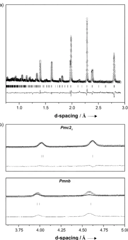
ments of neutron (HRPD, GEM) (Figure 2 a) and
synchro-tron X-ray (ID31) data. The Pmc21 refinement is superior
(Rwp=7.19 % versus 8.25 %), with the non-polarPmnbmodel
unable to satisfactorily fit the (110), (200), and (011) reflections (Figure 2 b).
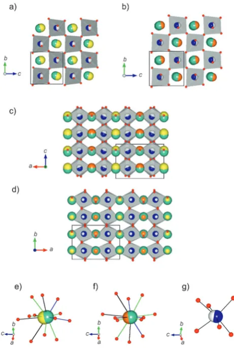
ThePmc21structure of 0.72BFTM–0.28LFO (Section 3.1,
Supporting Information) is adopted at low temperature by the
high-pressure form of the B-site-driven CdTiO3
ferroelec-tric,[9](though more recent neutron diffraction studies have
cast doubt on this[10]), the high field form of NaNbO 3[11]and
sol–gel synthesized NaNbO3.[12]There are one B site and two
A sites in the asymmetric unit, with the Rietveld refinement showing no indication of Bi/La cation ordering. The two A sites are arranged in alternating layers alonga(Figure 3 a and b). Each A site has a ferroelectric displacement with a distinct
amplitude (0.31 A1 and 0.17 A2) along thez ([110]p)
direction (Figure 3 c), and distinct BiO environments
(Fig-ure 3 e,f). The B site (Fig(Fig-ure 3 g) also has a 0.14 ferroelectric displacement along [110]p. There are also small (<0.05 )
antiferrodistortive displacements at both A sites alongbandc and at the B site alonga(Figure 3 d). The ionic polarization calculated[13]from the refined structure is 30.6mC cm2.
Measurement of the synchrotron X-ray and neutron powder diffraction patterns as a function of temperature
reveals a structural phase transition from Pmc21 to Pmnb
above 65058C (Figure S6). This structure (Section 3.2,
Supporting Information) maintains the a+
bbtilt system of
Pmc21. There is only one crystallographically distinct A site,
which is displaced 0.08 antiferrodistortively along [110]p
and no B-site displacement.
The atomic displacements for the polar Pmc21 BLFTM
structure and the high-temperature (HT)Pmnbphase can be
[image:2.595.313.533.56.466.2]understood in terms of distortion modes derived from the
Figure 1. a) Phase diagram of the Bi(Fe2/8Ti3/8Mg3/8)O3–LaFeO3–
La(Mg1/2Ti1/2)O3BLFTM system showing the four distinct categories of
phase assemblage found in the system (&Pmnb;~Pmc2 1;*
[image:2.595.59.284.56.431.2]two-phase mixture;~R3c) and b) evolution of the reduced lattice parameters along the BFTM–LFO line expressed as the composition of BFTM. Filled and open symbols correspond to materials shown to be centric and non-centric, respectively, by second harmonic generation measurements.
Figure 2. Rietveld refinement of a) neutron diffraction data (HRPD) for
0.72BFTM–0.28 LFO in space groupPmc21. b) Comparison of the fits
inPmc21(top) andPmnb(bottom) for the (110), (200), and (011)
reflections in 0.72BFTM–0.28LFO from the GEM neutron diffraction data. The circles represent the observed data, the thick line represents the model and the difference can be seen below.
Angewandte
Pm3m aparistotype cell, evaluated with the Isodisplace[14]and
Amplimodes[15] programs (for further details and mode
amplitudes see Section 3.3, Supporting Information).Pmnb
(basis={(2,0,0),(0,1,1)(0,1,1)}, origin=(0,0,0)) is produced by the R4
+
(Figure 4 b) antiphase a0b
b and in-phase M3
+
(Figure S8a) a+
b0b0 octahedral tilts which are the most
significant modes. The associated antiferrodistortive A-site
displacements along c, 0.08 from the centroids of their
coordinating oxygens, are from the X5
+
mode[16](Figure 4 c),
giving the observed single A-site structure. ThePmc21phase
(basis={(2,0,0),(0,1,1)(0,1,1)}, origin=(1=
2,1=2,0)) is driven
by the onset of the dominantG4
polar displacement at the A
and B sites (Figure 4 a). This ferroelectric displacement is along [110]p, as in theAmm2 (O) phase of BaTiO3[17]and the
high-field form of PbZrO3.
[18]In-phase combination of this ca.
0.22 magnitude polar displacement with the 0.08 anti-ferrodistortive displacement (X5
+
mode) present in thePmnb
precursor affords the 0.31 displacement at the A1 site, while the out-of-phase combination gives the 0.14 polar
displacement at the A2 site along the [110]pdirection. The
small A-site antiferrodisplacive R5
+
mode (Figure S8b) along bis unchanged betweenPmnbandPmc21. There is a single B
site inPmc21with theG4
-driven polar displacement alongc
accompanied by a smaller antiferroelectric displacement
along a from the X3 mode (Figure 4 d). Only one B site
results because the ferroelectric and antiferroelectric dis-placement directions are perpendicular.
Electrical properties of BLFTM were measured on
97+% dense ceramics, with dielectric loss reduced by the
addition of 0.2 wt % MnO2,[19]which lowers tandfrom 0.036
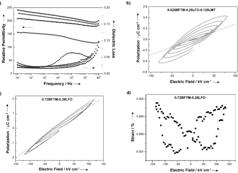
to 0.025 at 1 kHz and from 0.589 to 0.034 at 1 Hz for 0.72BFTM–0.28 LFO. The low-frequency loss (Figure 5 a) is comparable to other shared A-site Bi-based ferroelectrics for example, Na0.5Bi0.5TiO3 (>0.05 at 1 kHz).[20] 0.625BFTM–
0.25LFO–0.125LMT has the lowest tand, suggesting that
LMT is particularly effective in reducing the loss. All the Pmc21 [110]p displaced materials have higher permittivities
than [111]p displaced rhombohedral BFTM, and the broad
[image:3.595.304.540.57.274.2]step-like decrease in permittivity for BFTM above 1 kHz, suggestive of a relaxation phenomenon, is not observed in the new polar phase. The magnitude of the relative permittivity rules out the possibility of contributions from extrinsic charge carriers at grain boundaries or electrode–sample interfaces.[21]
Figure 3. Pmc21room temperature structure of 0.72BFTM–0.28LFO.
A-site cations represented in green, B-site cations blue, and oxygen atoms in red. The centroids of the oxide anions coordinating the A1 site are shown in yellow, A2 centroids orange, B centroids white. Viewed along theadirection, with a) the A1 layer on top and b) the A2 layer on top. c) Viewed alongbshowing the FE displacements of A1, A2, and B along thecdirection. d) Viewed alongcshowing the A1 and A2 AFE displacements alongband the B-site AFE displacements along
[image:3.595.55.286.58.401.2]a. e) Coordination environment of the A1 cation. There are four short BiO contacts (blue) four intermediate (green) and four long bonds (black). Displacement components (0,0.09 , 0.31 ) in the unit cell reference frame. f) Coordination environment of the A2 cation. This site has three short contacts (blue) and nine which are less distinctly separated than for A1, divided here into six bonds between 2.6 and 3 (green) and three bonds longer than 3 (black). Displacement components (0,0.03 , 0.17 ). g) B-site octahedral environment. Displacement components: (0.06 , 0.009 , 0.14 ).
Figure 4. Important displacement modes in thePmc21andPmnb
structures of BLFTM a)G4
ferroelectric displacement mode inPmc21,
b) R4+out-of-phase tilting mode (both structures), c) the X5+mode
which is responsible for A-site antiferrodistortive displacements along
cin both structures, and d) the X3
mode with antiferrodistortive B-site displacements alongainPmc21. A-site cations represented in white,
B-site cations black, and oxygen atoms in gray.
.
Angewandte
The polarity shown in the structure and SHG measure-ments was confirmed by measuremeasure-ments of piezoelectric
behavior. Strain-field measurement on Pmc21 0.72BFTM–
0.28LFO (Figure 5 d) shows a butterfly loop, with a negative strain component. This negative strain is related to domain back-switching during the bipolar cycles and demonstrates typical ferroelectric behavior.[22]The coercive field, calculated
from the minimum in the strain field plot, is equal to 62 kV cm1. The calculated strain is 0.003 % and the high-field
d33 value obtained from the strain-field measurements is
1.68 pC N1. The measured piezoelectric coefficient is
0.25 pC N1.
It was not possible to obtain a saturatedP(E) (P= polar-ization, E=electric field) hysteresis loop before dielectric
breakdown, which is a common problem in BiFeO3
ceram-ics.[23]This can be attributed to a high Curie temperature and
coercive field. The best P(E) loop came from the Pmc21
structure composition 0.625BFTM–0.25LFO–0.125LMT (Fig-ure 5 b). Although the loop is not saturated, electrical polar-ization does not evolve as a linear function of the driving-field amplitude indicating nonlinearity (a necessity for
ferroelec-trics) and therefore domain wall motion.[24] P(E) for
0.72BFTM–0.28LFO (Figure 5 c) is not saturated but shows
non-linearity, indicating the presence of domain wall motion, consistent with the strain-field measurement on this compo-sition.
Figure 6 represents the A-site displacements in polar structures derived from the ideal perovskite, with the effect of octahedral tilting in systems containing smaller A cations than Pb2+evident. The O’Pmc2
1structure found here corresponds
to the polarization direction changing from [111]pin the R’
parent phase BFTM to [110]p, driven by the substitution of
La3+
onto the A site, because of the tilts and displacements in this direction in LaFeO3. La
3+substitution into R’BiFeO
3also
induces [110]pA- and B-site displacements, but in this case the
displacements are coupled antiferrodistortively to produce
the antiferroelectric PbZrO3structure (Figure 6; OA’denotes
a tilted antiferroelectric structure).[25]The striking difference
in the coupling of the [110]p displacements in the present
BLFTM case may arise from the presence of Mg2+
and particularly Ti4+
on the B site in the BFTM parent, as Ti4+
produces ferroelectric [110]pdisplacements in O BaTiO3.[17]
The O’ structure features two A sites with distinct
polar-izations because of the competition between La-driven [110]p
antiferrodisplacive motions and the dominant ferroelectric
[image:4.595.60.541.58.407.2]displacements along the same direction driven by Bi3+ and
Figure 5. a) Room temperature permittivity and loss as a function of frequency of BFTM (!), 0.72BFTM–0.28LFO (*), 0.625BFTM–0.25LFO–
0.125LMT (&), and 0.58BFTM–0.42LFO (~). b)P(E) loop for 0.625BFTM–0.25LFO–0.125LMT, c)P(E) loop for 0.72BFTM–0.28LFO corresponding
to d) the strain-field loop of the same composition. The dotted line in (b) and (c) represent the slope of theP(E) loop at the lowest voltage and is used to demonstrate nonlinearity.
Angewandte
Ti4+, reflecting structural frustration between the bonding
preferences of the two A-site cations. In the present BLFTM
system, the O’ structure is separated by two-phase regions
involving non-perovskite impurities from the R’ structure,
and bridging this phase gap is important in the search for enhanced functionality associated with potential phase boun-daries differing in polarization direction.
Received: May 20, 2012
Published online: September 28, 2012
.
Keywords: bismuth · diffraction techniques · ferroelectricity · perovskites · polar structures[1] Y. Saito, H. Takai, T. Tani, T. Nonoyama, K. Takatori, T. Homma, T. Nagaya, M. Nakamur,Nature2004,432, 84. [2] a) T. Yamamoto,Jpn. J. Appl. Phys.1996,35, 5104; b) R. Guo,
L. E. Cross, S. E. Park, B. Noheda, D. E. Cox, G. Shirane,Phys. Rev. Lett.2000,84, 5423.
[3] J. Rçdel, W. Jo, K. T. P. Seifert, E.-M. Anton, T. Granzow, D. Damjanovic,J. Am. Ceram. Soc.2009,92, 1153.
[4] G. Catalan, J. Scott,Adv. Mater.2009,21, 2463.
[5] H. Hughes, M. Allix, C. A. Bridges, J. B. Claridge, X. Kuang, H. Niu, S. Taylor, W. Song, M. J. Rosseinsky,J. Am. Chem. Soc. 2005,127, 13790.
[6] C. A. Bridges, M. Allix, M. R. Suchomel, X. Kuang, I. Sterianou, D. C. Sinclair, M. J. Rosseinsky,Angew. Chem.2007,119, 8941;
Angew. Chem. Int. Ed.2007,46, 8785.
[7] a) A. N. Salak, O. Prokhnenko, V. M. Ferreira,J. Phys. Condens. Matter2008,20, 085210; b) D.-Y. Lee, S.-J. Yoon, J. H. Yeo, S. Nahm, J. H. Paik, K.-C. Whang, B.-G. Ahn,J. Mater. Sci. Lett. 2000,19, 131.
[8] K. M. Ok, E. O. Chi, P. S. Halasyamani,Chem. Soc. Rev.2006,
35, 710.
[9] Y. J. Shan, H. Mori, K. Tezuka, H. Imoto, M. Itoh,Ferroelectrics 2003,284, 107.
[10] B. J. Kennedy, Q. Zhou, M. Avdeev,J. Solid State Chem.2011,
184, 2987.
[11] V. A. Shuvaeva, M. Y. Antipin, S. V. Lindeman, O. E. Fesenko, V. G. Smotrakov, Y. T. Struchkob,Ferroelectrics1993,141, 307. [12] K. E. Johnston, C. C. Tang, J. E. Parker, K. S. Knight, P.
Light-foot, S. E. Ashbrook,J. Am. Chem. Soc.2010,132, 8732. [13] S. C. Abrahams,Acta Crystallogr. Sect. B2002,58, 34. [14] B. J. Campbell, H. T. Stokes, D. E. Tanner, D. M. Hatch,J. Appl.
[image:5.595.95.505.54.416.2]Crystallogr.2006,39, 607.
Figure 6.Examples of perovskites with A-site ferroelectric displacements along the [001]p, [110]p, and [111]pdirections in relation to the ideal
cubic perovskiteapcell. The tilted T’structure of BiInO3is only accessible at high pressure:[26]only the FE displacements are shown as the
bismuth ion has an AFE component as well. The polar O’structure observed for BLFTM in the present study contrasts with the antiferrodistortive coupling of [110]pdisplacements in the PbZrO3structure of La-substituted R’BiFeO3. The arrow representing the displacements in M-PZT
indicates a Pb2+displacement mainly along [100]
p, but with a significant component along [110]p.
.
Angewandte
[15] a) D. Orobengoa, C. Capillas, M. I. Aroyo, J. M. Perez-Mato,
Appl. Crystallogr. 2009, 42, 820; b) J. M. Perez-Mato, D. Orobengoa, M. I. Aroyo,Acta Crystallogr. Sect. A2010,66, 820. [16] R. B. Macquart, B. J. Kennedy, M. Avdeev,J. Solid State Chem.
2010,183, 2400.
[17] G. Shirane, H. Danner, R. Pepinsky,Phys. Rev.1957,105, 856. [18] B. A. Scott, G. Burns,J. Am. Ceram. Soc.1972,55, 331. [19] S. O. Leontsev, R. E. Eitel,J. Am. Ceram. Soc.2009,92, 2957. [20] T. Wada, K. Toyoike, Y. Imanaka, Y. Matsuo,Jpn. J. Appl. Phys.
2001,40, 5703.
[21] V. Bobnar, A. Levstik, C. Huang, Q. M. Zhang,Phys. Rev. B 2005,71, 041202.
[22] a) C. W. Ullah, A. Ahn, A. Hussain, S. Y. Lee, W. Kim,J. Am. Ceram. Soc. 2011, 94, 3915; b) T. P. Comyn, T. Chakraborty, R. E. Miles, S. J. Milne,Appl. Phys. Lett.2008,93, 052909.
[23] a) W.-M. Zhu, H.-Y. Guo, Z.-G. Yea,J. Mater. Res.2007,22, 21362143; b) J. Wei, R. Haumont, R. Jarrier, Berhtet, Dkhil,
Appl. Phys. Lett.2010,96, 102509.
[24] S. Li, W. Cao, L. Cross,J. Appl. Phys.1991,69, 7219.
[25] a) S. Karimi, I. M. Reaney, Y. Han, J. Pokorny, I. Sterianou,J. Mater. Sci.2009,44, 5102; b) I. Levin, S. Karimi, V. Provenzano, C. L. Dennis, H. Wu, T. P. Comyn, T. J. Stevenson, R. I. Smith, I. M. Reaney,Phys. Rev. B2010,81, 020103; c) D. A. Rusakov, A. M. Abakumov, K. Yamaura, A. A. Belik, G. Van Tendeloo, K. Takayama-Muromachi,Chem. Mater.2011,23, 285. [26] A. A. Belik, S. Y. Stefanovich, B. I. Lazoryak, E.
Takayama-Muromachi,Chem. Mater.2006,18, 1964.
![Figure 6. Examples of perovskites with A-site ferroelectric displacements along the [001]p, [110]p, and [111]p directions in relation to the idealcubic perovskite ap cell](https://thumb-us.123doks.com/thumbv2/123dok_us/7989026.204920/5.595.95.505.54.416/examples-perovskites-ferroelectric-displacements-directions-relation-idealcubic-perovskite.webp)
