This is a repository copy of Finite Element Analysis of Progressive Degradation versus
Failure Stress Criteria on Composite Damage Mechanics.
White Rose Research Online URL for this paper:
http://eprints.whiterose.ac.uk/94874/
Version: Accepted Version
Book Section:
Curiel Sosa, J.L. (2011) Finite Element Analysis of Progressive Degradation versus Failure
Stress Criteria on Composite Damage Mechanics. In: Attaf, B., (ed.) Advances in
Composite Materials - Ecodesign and Analysis. INTECH . ISBN 978-953-307-150-3
https://doi.org/10.5772/13886
eprints@whiterose.ac.uk
https://eprints.whiterose.ac.uk/
Reuse
Unless indicated otherwise, fulltext items are protected by copyright with all rights reserved. The copyright
exception in section 29 of the Copyright, Designs and Patents Act 1988 allows the making of a single copy
solely for the purpose of non-commercial research or private study within the limits of fair dealing. The
publisher or other rights-holder may allow further reproduction and re-use of this version - refer to the White
Rose Research Online record for this item. Where records identify the publisher as the copyright holder,
users can verify any specific terms of use on the publisher’s website.
Takedown
If you consider content in White Rose Research Online to be in breach of UK law, please notify us by
0
Finite Element Analysis of Progressive
Degradation versus Failure Stress Criteria on
Composite Damage Mechanics
J.L. Curiel Sosa
Materials and Engineering Research Institute, Sheffield Hallam University United Kingdom
1.Introduction
It is well known that the engineering applications using composite materials is in constant growth, mainly because of the large strength/weight ratio that they provide. The modelling of these materials has been of interest for a long time, due to the experimental costs that can be saved by means of computer simulations. However, the mixed mode of failure in composite materials makes it a complicated task to deal with, resulting often in sophisticated damage models.
computational techniques for modelling damage progressively were developed to adapt to the finite element methodology. The progressive damage causes the degradation of the stiffness in the damaged zone. Thus, a damaged finite element does not lose completely its loading bearing capacity but the latter is decreased inversely proportional to the degree of damage. The progressive damage models derive from the thermodynamical approaches proposed by Kachanov (1958) initially and, most famously acknowledged by Lemaitre (1992); Lemaitre and Chaboche (1990) and Chaboche (1981). Proposals in this field by Matzenmiller et al. (1995), Maimi et al. (2007a;b), Barbero & De Vivo (2001) or Schipperen (2001) have contributed to extend the number of techniques available for damage evolution on composite materials.
The progressive damage models are attractive as they are readily implemented either in major codes or in-house finite element programs. Nevertheless, these models have the uncertainty on when the onset of damage is reproduced. Some authors coupled it to stress criteria as initiation criteria for developing damage to solve this drawback. For instance, Lapczyk & Hurtado (2007) combined a progressive damage model with the stress criteria proposed by Hashin (1980) as a damage initiation criteria. The formulation is based on the fracture energy for representation of fibre failure and matrix failure. Hufenbach et al. (2004) have successfully shown how interactive criteria –combining progression and failure criteria– may be applied for the prediction of failure in textile reinforced composites assuming that they are formed by unidirectional layers. However, Cuntze & Freund (2004) state that the conditions of initiation of failure are not as relevant as the evolution of the stiffness degradation, due to the fact that its influence is decreasing with the damage progression. This is in agreement with other theories that defend the inelastic behaviour of a range of composite materials, (Barbero & Lonetti, 2002). Chow and Yang (1998) developed an inelastic model for the description of damage in composite laminates and its implementation into an incremental displacement-based Finite Element Method(FEM). The stress strain relationship is incorporated into a modified Newton-Raphson iterative method. More recently, Zobeiry et al. (Camanho et al., 2008) presented a progressive damage model with special attention to the nonlocal regularisation of the damage computations. A significant number of these last approaches are limited to plane stress models, such as those by, for example, Allen et al. (1987); Edlun and Volgers (2004); Harris et al. (1995); Hochard et al. (2001); Talreja (1987); Tan (1991) and McCartney (2003). In the best of knowledge, pioneering works on nonlinear behaviour of composites were developed by Chang and Chang (1987) and by Shahid and Chang (1995). Both works are dedicated to the analysis of composite plates. Lessard and Shokrieh (1995) state that two-dimensional analysis may produce sensibly different results as a consequence of the anisotropy induced by distinct modes of damage in the originally orthotropic composite. Nowadays, three dimensional models for laminates are readily implemented in computational techniques due to advances in computer power and programming facilities.
of having excessive refinement of the mesh in the proximities of the crack tip which is also an advantage for computational saving. VCCT has the problem, like progressive damage models based in thermodynamical theory, of not having an initiation criteria for propagation of the fracture. The use of cohesive elements has been recently boosted. An excellent works by Camanho & Mathews (1999); Camanho et al. (2003) or Iannucci and Willows (2006) show a damage progression scheme combined with interface elements to couple the damage evolution with the mechanics of the fracture. An excellent review of these technique is provided by Wisnom (2010). Cohesive models are preferred to VCCT technique for a growing number of authors, such as Dugdale (1960), Xie & Waas (2006), Turon et al. (2007)), Tvergaard & Hutchinson (1996), Allen & Searcy (2000), or Cox & Yang (2006). Camanho et al. (2008) and also Hallet (1997) have used interface elements for the prediction of delamination on laminates.
In this chapter, finite element analysis is applied to laminates, and the formulation of the model is developed at lamina scale. The laminate is a stack of laminae of different, in general, fibre orientations. An explicit integration strategy for the finite element analysis is used due to the simplicity and robust convergence that provide1. The model is adapted in order to
be included into an explicitFEM (see explicit formulation in Curiel Sosa et al. (2006) for implementation details) whereby the transient response may be conveniently simulated. This chapter is outlined as follows: firstly, a general discussion over damage modes is performed; secondly, the main theoretical aspects of the model are shown; thirdly, the computational algorithm, for implementation of the damage model as an individual module into an in-house
FEMprogram as well as in major commercial software packages such as Abaqus or Ansys, is provided; and finally, a set of numerical examples including the low velocity impact on a composite laminate[0, 90]a.
2. Composite damage modes
The damage in composites is generally represented by several modes: matrix cracking, matrix crushing, fibre kinking, fibre rupture or breakage. From a modelling point of view, one may find in the literature different choices of mixed modes of damage in composites. Hashin (1980) considered in his stress criteria four modes:
• matrix failure in tension and compression represented by a criterion that includes transverse-to-fibres stress and a combination of shear stresses.
• fibre-matrix disbonding as a function of the longitudinal stress and shear stresses.
• fibre failure in compression or tension, depending upon the limit values of the axial stresses.
• delamination.
Similar mixed modes criteria were used by Chang and Lessard (1991) which were coded by Ambur et al. (2004) as anAbaqus user subroutine for the reader interested in this type of computer implementations. They modelled the progression of the damage modes proposed by Hashin (1980) and applied it to the simulation of composite shells. No implementations to 3D solid elements were shown. Some authors, for example Curiel Sosa et al. (2008a); Curiel Sosa (2008b); Matzenmiller et al. (1995), take into account the following damage modes for modelling:
• fibre rupture.
• fibre kinking.
• matrix cracking.
• matrix crushing.
In the progressive damage model presented in Section3a three dimensional element is used rather than shells and, hence, a general description of the modes is more appropriate under these premises. Delamination is in an upper material scale and is implicitly implemented in the general flow of the procedure as matrix cracking may eventually result in delamination. In this manner, inelasticity is integrated straightforward within the model. It is well-known from experimental evidence that the idealisation of composite behaviour as linear elastic is inadequate (Chang and Lessard, 1991; Xu, 1994) as inelastic deformations evolve not only due to micro-cracks at the micro-scale but also due to complex damage modes occurring at the macroscale, leading, eventually, to the total failure. Contrary to purely brittle materials, the fibre-reinforced composite material exhibits at some extent a softening behaviour preceding the total failure. This phenomenon, from a strictly thermodynamical point of view, is related to the dissipative (irreversible) process that rearranges the distribution of material properties due to the presence of damage.
3. Progressive damage modelling (PDM)
In this section, a progressive damage model for composites (PDM) is presented (Curiel Sosa et al., 2008a; Curiel Sosa, 2008b), the results of this model are then compared with the outcome of some stress failure criteria. The formulation concerning the implementation of the damage model is also presented below. In PDM, it is assumed that different damage modes develop simultaneously on the failed composite structure and that they can interact directly influencing each other. The approach presented may be framed within the continuum damage mechanics field. The damage variables represent the state of damage at any stage of deterioration. They are implicitly defined for what they may be considered internal state variables that can provide a quantifiable magnitude of the degradation of the composite material. In PDM, damage variables are referred to damage modes via superposition. Thus, a damage mode is represented for one or more than one damage variables with distinct weights as explained below. The adopted damage modes, generically denoted asγ, are modelled by means of a linear combination of growth functionsΦγ
and damage directorsvγ
(Curiel Sosa et al., 2008a). In summary, PDM admits the modelling of different damage modes that can be integrated directly in the description of damage through Equation (6)which is explained on Section (4).
Thus, the damage state may be defined by a series of internal variablesωkj, filling the diagonal damage tensorD(see Equation (1)) that represents the state of damage in the composite.
ˆ
σ = D·σ (1)
where σT = [σ
11,σ22,σ33,σ12,σ23,σ31] is an array formed by the stress components and
ˆ
σ is the so-called effective stress array (Chaboche, 1981). The definition of tensors and
in the longitudinal direction to the fibres whereas the other two axes, i.e. 2 and 3, are in perpendicular direction to fibres.
The damage tensor is built as a diagonal tensor and contains the damage internal variables
ωkj, see Equation (2). These are responsible for the degradation of the stiffness components.
diag(D) =
·
1 1−ω11
, 1 1−ω22
, 1 1−ω33
, 1 1−ω12
, 1 1−ω23
, 1 1−ω31
¸
(2)
The effective stresses ˆσare assumed to fulfil the strain equivalence principle (Lemaitre and
Chaboche, 1990) resulting, eventually, in Equation (3).
ˆ
σ = C0·ε (3)
Inverting the damage tensorDand substituting Equation (1) into Equation (3), renders the
stress-strain constitutive law, Equation (4).
σ = D−1·C
0·ε = C(ω)·ε (4)
whereC0is the stiffness matrix. It should be noticed that the introduction of the degradation
internal variablesωijyields a non-symmetric tensorC(ω)(see Equation (5)). The matricesA
andB, defined in a local system of reference, are introduced in order to read Cin a more
compact manner.
A(ω) =
(1−ω11)(1−ν23ν32) E22E33∆
(1−ω11)(ν12+ν32ν13) E11E33∆
(1−ω11)(ν13+ν12ν23) E11E22∆
(1−ω22)(ν12+ν32ν13) E11E33∆
(1−ω22)(1−ν13ν31) E11E33∆
(1−ω22)(ν23+ν21ν13) E11E22∆
(1−ω33)(ν13+ν12ν23) E11E22∆
(1−ω33)(ν23+ν21ν13) E11E22∆
(1−ω33)(1−ν12ν21) E11E22∆
where∆is a determinant that depends upon the elastic properties,
∆ = (1−ν12ν21−ν23ν32−ν31ν13−2ν21ν32ν13)
E11E22E33
B(ω) =
(1−ω12)G12 0 0
0 (1−ω23)G23 0
0 0 (1−ω31)G31
Note that the’damaged’stiffness tensorC∈ R6×6is built as follows,
C(ω) =
·A
(ω) O O B(ω)
¸
(5)
whereO∈ R3×3is a matrix filled with zeros.
4. Definition of damage internal variables
The time variation of damage internal variables is defined as a linear combination of theΦγ
growth functions and the damage directors (Equation (6)).
˙
ω=
nmodes
∑
γ=1 Φγvγ
In the above,γdenotes a mode of damage andnmodesdenotes the total number of failure modes. The growth functions for each damage modeγare computed through Equation (7).
Φγ
=<∇εgγ
, ˙ε>+ (7)
where∇εis the strain gradient ∂
∂εand ˙εthe strain rate.<·>+denotes the non-negative inner
product accounting for the trespassing on the damage surface. The subscript+indicates that the inner product vanishes for negative values. This ensures that there is no growth of damage if the damage surface is not reached. If the strain increment vector is pointing to the interior of the surface (for a generic damage modeγ) there is no progression of that particular damage mode. So a simple way to effectively computing this is to perform the nonnegative scalar product as represented in equation (7). In Equation (8),gγ
are the evolving damage surfaces in the strain space.
gγ = εT·Gγ·ε−
cγ
(8) where cγ is an empirical parameter defining the damage surface. The variations of these
surfaces on the strain space result in Equation (9). It should be noticed thatcγare not needed
in the numerical scheme as Equation (9) is the one necessary for the computational procedure. In this manner, the number of experimental data, which are difficult, or even impossible with the current techniques to obtain, are sensibly reduced.
∇εg
γ=εT·(GγT+Gγ)
(9)
After some algebra, Gγ
second-order tensors are derived from Equation (3) and from the equivalence of the quadratic forms in stress and strain spaces given by Equation (10) (Curiel Sosa et al., 2008a).
σT·Fγ·σ = εT·Gγ·ε
(10)
Ffl
are second-order tensors are derived from damage surfaces defined on the stress space. The modelling of the unitary damage directorsvγis based upon the stiffness components that are
degraded when a particular mode of damage occurs. For instance, fibre rupturev(1)affects to
the stiffness degradation in(11),(12)and(31)directions,
v(1) = hλ(1) 11 0 0λ
(1) 12 0λ
(1) 31
iT
The weightsλγ
ijmay be estimated from experimental observations in a qualitative manner for
the corresponding damage mode. This technique is still being researched to provide a more straightforward computational strategy that allows to update vγ
at every time step of the numerical procedure. Techniques such asInverse ModellingorOptimizationare also possible for a more efficient modelling ofvγ
. However, at present, no attempt of using these techniques is being made.
5. PDM algorithm
The PDM algorithm has been implemented into an in-houseFEM. Additionally, it was coded within AbaqusTM as avumat subroutine. It is adapted for the majority of the commercial
at each quadrature point. This is gathered in step (I) below. The computational algorithm is briefly outlined as follows,
I. Loop over damage modes, forγ=1 toγ=nmodesdo:
i. Compute the’damaged’stiffness tensor:C(ω).
ii. GenerateFγ. Note that theγsuperscript may be treated as a third index which may
provide clarity to the code.
iii. Calculate:Gγ = CT·Fγ·C. Eachγgives place to a distinct damage surface in the
strain spacegγ
, i.e. one for every damage mode (see Equation (8)). Calculation ofgγ
is not required asGγ
is the only entity needed for the following steps.
iv. Strain gradient of damage in strain space:∇εg
γ=εT·(GγT+Gγ)
.
v. Growth of damageγ:Φγ=<∇
εgγ, ˙ε>+
vi. Directional damage vector:vγ
II. For current gauss point, compute the damage internal variables array as a linear combination of damage directors and damage mode growth: ˙ω=∑nmodesk=1 Φγvγ.
6. Numerical examples
6.1 Tension and compression tests
In this section, tension and compression tests on a fibre reinforced composite are presented using the PDM algorithm. The lamina is formed by longitudinal glass fibres embedded firmly within an epoxy matrix. The material parameters for the tests are: Youngt’s modulus
E1=126GPa,E2=E3=11GPa, Poisson ratiosν12=ν13 =0.28,ν23 =ν32 =0.4,ν21 =ν31=0.024
normal strengthsX11=1950MPa,X22=X33=48MPa, and shear strengthsS12=S31=79MPa.
The load is a distributed force applied incrementally in parallel direction to the fibres up to complete failure, i.e. until the lamina can not withstand the load any longer. The load is applied over one of the sides of dimension 1m×0.1m, whilst the opposite side is constrained
in motion.
Charts represent the evolution of variables and parameters at the interior central point, i.e. centre of mass. Figure (1) displays the stress vs. strain relationship from the numerical simulation and comparison with the experimental data for the tension test. A misplacement can be observed in the slope corresponding to the linear elastic behaviour. However, this is not sensibly affecting the overall response and , in particular, the softening response in the nonlinear inelastic regime in which the proposed model is focused. A numerical quantification of each damage mode are the internal variables Φγwhich represent the evolution of each
damage mode. In other words, the evolution ofΦγis a numerical quantifiable representation
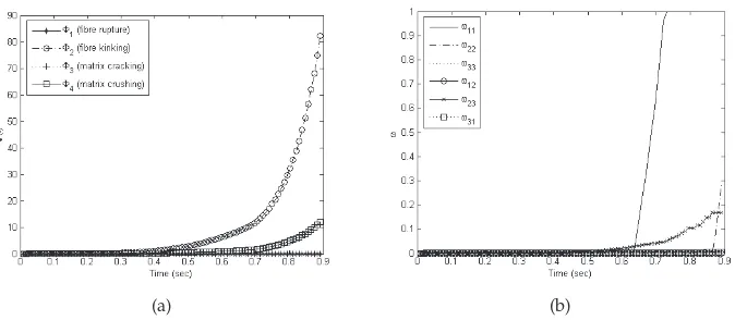
of the damage mode γallowing to know what are the magnitude of a particular damage mode and its relation to the remaining damage mode evolutions to be determined. It should be expected that the damage modes in tension would be fibre rupture and matrix cracking and, on the contrary, the damage modes that should evolve in compression would be fibre kinking and matrix crushing. This is what PDM detects efficiently as proved in Figure (2) for the tension test and, in Figure (3) for the compression test. This is an excellent characteristic of PDM as it permits the detection of the correct damage mode depending upon the stress state in corresponding region or domain. Thus, for example, Φ2 corresponding to fibre kinking
Fig. 1. Stress vs strain relationship in fibre direction for the tension test.
(a) (b)
[image:9.482.77.414.392.539.2](a) (b)
Fig. 3. Compression test –longitudinal direction to the fibres:(a) Evolution of each damage mode growth parameter. (b) Damage internal variables time evolution.
rupture or breakage and matrix cracking are the only modes expected in a tension test. This is in agreement with the computational model output, see Figure (2a). Also, the internal variablesωijshows how the different damage modes affect the degradation of the stiffness
components (see Equation (4)). In Figure (2b), it is observed, as expected, thatω11increases
in an exponential manner. Eventually, it reached the maximum of 1 which is equivalent to complete failure.
In the compression test, the modes of damage obtained are fibre kinking and matrix crushing. This is in agreement with the mechanics of the composite as no other sort of damage should be observed in the centre of the sample in this test. As the failure is significantly affecting the longitudinal direction, again, the internal variable subjected to a higher rate of increment is
ω11, see Figure (3b).
6.2 Impact on[0/90]alaminate
In this section, the proposed model is tested by means of a well known three-dimensional example with clear matrix crushing and matrix cracking damage developments. This test consists of a low velocity impact –7.08ms−1– on a laminate [0/90]
a formed by 21 alternate
laminae, see Figure4, made of carbon fibres and epoxy resin. The composite obtained is a transversally isotropic fibre reinforced composite material with a volume fraction of 60%. Experimental tests were conducted by Hallet (1997) using a Hopkinson bar apparatus, see (Hou et al., 2000) for more details of the set-up of this experiment. Basically, the projectile is a titanium alloy rod with a diameter of 9.55mmand a total length of 500mmand its head is rounded in order to damp the vibrations. The mass of the projectile was calibrated to 260gto strictly replicate the experiment.
The dimensions of the laminate were 2.6x85x85mm3and it is supported by a steel ring with an
projectile
laminate
support
(a)
laminate
support
[image:11.482.126.399.69.199.2](b)
Fig. 4. Initial setup: (a) A quarter of the real configuration is used in the numerical tests thanks to the symmetry. (b) A closer snapshot of the laminate and the support.
well as in the numerical tests conducted by Hou et al. (2000), a matrix crushing zone was observed just beneath the contact region, i.e. in the through-thickness compression region under the projectile. The numerical result for matrix crushing region from the proposed model is depicted in Figure5. It may be observed that the matrix crushing zones are located in agreement with the experimental results by Hallet (1997); Hou et al. (2000). The progressive development of those regions is more realistic than the result obtained using just stress failure criteria as depicted in Figure (6) which provides Boolean values for the damage variables without considering any progression of the damage. In the computational results using PDM, neither fibre rupture nor fibre kinking were developed as expected with that impact velocity. To turn off the damage modes according to physical reality is an excellent characteristic of PDM.
7. Conclusion
This chapter has provided an overview of the different techniques used for modelling damage in composites briefly showing the current state-of-art of the topic. Basically, from a computational point of view, there are two main trends:
• failure criteria which generally use a stress quadratic form.
• a progressive evolution of the damage.
(Ave. Crit.: 75%) SDV2 +0.000e+00 +9.460e-05 +1.892e-04 +2.838e-04 +3.784e-04 +4.730e-04 +5.676e-04 +6.622e-04 +7.568e-04 +8.514e-04 +9.460e-04 +1.041e-03 +1.135e-03 (a)
(Ave. Crit.: 75%) SDV2 +0.000e+00 +1.658e-04 +3.315e-04 +4.973e-04 +6.631e-04 +8.289e-04 +9.946e-04 +1.160e-03 +1.326e-03 +1.492e-03 +1.658e-03 +1.823e-03 +1.989e-03 (b)
(Ave. Crit.: 75%) SDV2 +0.000e+00 +2.317e-04 +4.634e-04 +6.951e-04 +9.268e-04 +1.159e-03 +1.390e-03 +1.622e-03 +1.854e-03 +2.085e-03 +2.317e-03 +2.549e-03 +2.780e-03 (c)
(Ave. Crit.: 75%) SDV2 +0.000e+00 +2.804e-04 +5.608e-04 +8.411e-04 +1.122e-03 +1.402e-03 +1.682e-03 +1.963e-03 +2.243e-03 +2.523e-03 +2.804e-03 +3.084e-03 +3.365e-03 (d)
(Ave. Crit.: 75%) SDV2 +0.000e+00 +6.125e-04 +1.225e-03 +1.838e-03 +2.450e-03 +3.063e-03 +3.675e-03 +4.288e-03 +4.900e-03 +5.513e-03 +6.125e-03 +6.738e-03 +7.350e-03 (e)
[image:12.482.62.432.65.464.2](Ave. Crit.: 75%) SDV2 +0.000e+00 +9.863e-04 +1.973e-03 +2.959e-03 +3.945e-03 +4.931e-03 +5.918e-03 +6.904e-03 +7.890e-03 +8.877e-03 +9.863e-03 +1.085e-02 +1.184e-02 (f)
Fig. 5. Development of matrix crushing damaged zone and grades in the laminate when impacted at 7.08m s−1.
Fig. 6. Matrix cracking pattern using a classical failure criterium based on stress components. The elements in red fulfilled the criterium which means that they are not withstanding loads any longer.
[image:13.482.58.426.249.540.2]8. References
Allen, D.H., Harris, C., & Groves, S.E. (1987). A thermomechanical constitutive theory for elastic composites with distributed damage. Part I: theoretical development.Int. J. Solids Struct.Vol.23(No. 9):1301-1318.
Allen, D.H. & Searcy, C.R. (2000). Numerical aspects of a micromechanical model of a cohesive zone.Journal of Reinforced Plastics and Composites,Vol.19(No. 3):240–248.
Ambur, D.R., Jaunky, N., Hilburger M. & Dávila C.G. (2004). Progressive failure analyses of compression-loaded composite curved panels with and whithout cutouts.Composite StructuresVol.65:143-155.
Barbero, E.J. & De Vivo, L. (2001). Constitutive model for elastic damage in fiber-reinforced pmc laminae.International Journal of Damage Mechanics,Vol.10(No. 1):73–93.
Barbero, E.J. & Lonetti, P. (2002) An inelastic damage model for fiber reinforced laminates.
Journal of Composite Materials,Vol.36(No. 8):941–962.
Boso, D., Pellegrino, C., Galvaneto, U. & Schrefler, B.A. (2000). Macroscopic damage in periodic composite materials.Commun. Numer. Meth. Engng.Vol.16:615-623.
Camanho, P.P. & Mathews, F.L. (1999). A progressive damage model for mechanically fastened joints in composite laminates.J. Composite Mater.Vol.33(24):2248-2280.
Camanho, P.P., Dávila, C.G. & de Moura, M.F. (2003) Numerical simulation of mixed-modes progressive delamination in composite materials. J. Composite Mater.Vol. 37 (No.
16):1415-1438.
Camanho, P.P., Dávila, C.G., Pinho, S.T. & Remmers, J.J.C. (2008). Mechanical Response of Composites: Preliminary Entry 10 (Computational Methods in Applied Sciences). Springer. Cox, B. & Yang, Q. (2006). In quest of virtual tests for structural composites. Science,Vol.314
(No. 5802):1102–1107, 2006.
Chaboche, J-L. (1981). Continuous Damage Mechanics–a tool to describe phenomena before crack initiation.Nucl. Engng. Des.Vol.64:233-247.
Chang, F-K. & Chang, K.Y. (1987). A progressive damage model for laminated composites containing stress concentration.J. Composite Mater.Vol.21:834-855.
Chang F.K.& Lessard L.B. (1991). Damage Tolerance of Laminated Composites Containing an Open Hole and Subjected to Compressive Loadings: 1 Analysis.J. Composite Mater.
Vol.25:2-43.
Chow C.L. & Yang F. (1998). Inelastic finite element analysis of fibre-reinforced composite laminates with damage.Proc Instn Mech Engrs Part CVol.212:717-729.
Cuntze, R.G. & Freund, A. (2004). The predictive capability of failure mode concept-based strength criteria for multidirectional laminates. Composites Science and Technology,
Vol.64(3-4):343–377.
Curiel Sosa, J.L., de Souza Neto, E.A. & Owen D.R.J. (2006). A combined implicit-explicit algorithm in time for non-linear finite element analysis. Commun. Numer. Meth. Engng.Vol.22:63-75.
Curiel Sosa, J.L., Petrinic, N. & Wiegand, J. (2008). A three-dimensional progressive damage model for fibre-composite materials.Mechanics Research CommunicationsVol.35 (No.
4):219-221.
Daniel, I.M. (2007). Failure of composite materials.StrainVol.43:4-12.
Dugdale, D.S. (1960). Yielding of steel sheets containing slits. Journal of the Mechanics and Physics of Solids,Vol.8(No. 2):100–104.
Edlund, U. & Volgers, P. (2004). A composite ply failure model based on continuum damage mechanics.Composite StructuresVol.65:347-355.
Hallet, S.R. (1997). Small specimen impact testing and modelling of car- bon fibre T300/914. PhD thesis, University of Oxford.
Harris, C.E., Coats, T.W., Allen, D.H. & Lo, D.C. (1995). A progressive damage model and analysis methodology for predicting the residual strength of composite laminates.J. Compos. Technol. Res.Vol.29:926-981.
Hashin, Z. (1980). Failure criteria for unidirectional fiber composites. J. App. Mech. Vol.
47:329-334.
Hibbit, Karlsson, & Sorensen (2007). Abaqus.User Manual.
Hinton, M.J. & Soden, P.D. (1998). Predicting failure in composite laminates: the background to the exercise.Compos. Sci. Technol.Vol.58:1001-1010.
Hinton, K.J., Kaddour, A.S. & Soden, P.D. (2004) A further assessment of the predictive capabilities of current failure theories for composite laminates: Comparison with experimental evidence.Compos. Sci. Technol.Vol.64 (No. 3-4):549-588.
Hochard, C., Auburg, P.A. & Charles, J.P. (2001). Modelling of the mechanical behaviour of woven fabric CFRP laminates up to failure.Compos. Sci. Technol.Vol.61:221-230, 2001.
Hoffman, O. (1967). The brittle strength of orthotropic materials.Journal of Composite Materials,
Vol.1(No. 2):200–206.
Hou, J.P., Petrinic, N., Ruiz, C. & Hallet, S.R. (2000). Prediction of impact damage in composite plates.Compos. Sci. Technol.Vol.60:273-281.
Hufenbach, W., Bohm, R., Kroll, L. & Langkamp, A. (2004). Theoretical and experimental investigation of anisotropic damage in textile-reinforced composite structures.Mechs. Compos. Mater.Vol.40(6):519-532.
Iannucci, L. & Willows, M.L. (2006). An energy based damage mechanics approach to modelling impact onto woven composite materials. Part I: Numerical models.
Composites: Part AVol.37:2041-2056.
Irwin G.R. (1948).Fracture dynamics, fracturing of metals,Vol.8:147–66.
Kachanov L.M. (1958). Time of the rupture process under creep conditions. Izv. Akad. Nauk. SSR,Vol.8(No. 8):26–31.
Lapczyk, I. & Hurtado, J.A. (2007). Progressive damage modeling in fiber-reinforced materials.
Composites Part A: Applied Science and Manufacturing,Vol.38(No. 11):2333–2341.
Lemaitre J. (1992).A Course on Damage Mechanics.
Lemaitre J, Chaboche J-L. 1990.Mechanics of Solids Materials.Cambridge University Press. Leski, A. (2007). Implementation of the virtual crack closure technique in engineering fe
calculations.Finite Elements in Analysis and Design,Vol.43(No. 3):261–268.
Lessard, L.B. & Shokrieh, M.M. (1995). 2-D modelling of composite pinned-joint failure.J. Composite Mater.Vol.29(No. 5):671-697.
McCartney, L.N. (2003). Physically based damage models for laminated composites. Proc. Instn. Mech. Engrs. – J. Mater. Design and AplicationVol.217 (No. L3):163-199.
Maimi, P., Camanho, P.P., Mayugo, J.A. & Dávila, C.G. (2007a). A continuum damage model for composite laminates: Part i - constitutive model. Mechanics of Materials,Vol.39
Maimi, P., Camanho, P.P., Mayugo, J.A. & Dávila, C.G. (2007b). A continuum damage model for composite laminates: Part ii - computational implementation and validation.
Mechanics of Materials,Vol.39(10):909–919.
Matzenmiller, A., Lubliner, J. & Taylor, R.L. (1995). A constitutive model for anisotropic damage in fiber-composites.Mechs. Mater.Vol.20:125-152.
Puck, A. & Schurmann, H. (1998). Failure analysis of FRP laminates by means of physically based phenomenological models.Compos. Sci. Technol.Vol.58:1045-1067.
Rybicki, E.F. & Kanninen, M.F. (1977). A finite element calculation of stress intensity factors by a modified crack closure integral. Engineering Fracture Mechanics,Vol.9(No. 4):
931–938.
Rybicki, E.F., Schmueser, D.W. & Fox, J. (1977). Energy release rate approach for stable crack growth in the free-edge delamination problem.Journal of Composite Materials,Vol.11:
470–487, 1977.
Shahid, I. & Chang, F-K.(1995). An acumulative damage model for tensile and shear failure of laminated composite plate.J. Compos. Mater.Vol.29:926-981.
Schipperen J.H.A. (2001). An anistropic damage model for the description of transversematrix cracking in a graphite-epoxy laminate.Composite Structures,Vol.53(No. 3):295–299.
Soden, P.D., Hinton, M.J. & Kaddour, A.S. (1998a). A comparison of the predictive capabilities of current failure theories for composite laminates.Compos. Sci. Technol.Vol.58 (No.
7):1225-1254.
Soden, P.D., Hinton, M.J. & Kaddour, A.S. (1998b). Lamina properties, lay-up configurations and loading conditions for a range of fibre-reinforced composite laminates.Compos. Sci. Technol.Vol.58 (7):1011-1022.
Swanson, J. (2007). Ansys.User Manual.
Talreja, R. (1987). Modelling of damage development in composites using internal variables concepts.Proceedings of the ASME, Damage Mechanics in Composites, ADVol.12:11-16.
Tan, S.C. (1991). A progressive failure model for composite laminates containing openings.J. Composite Mater.Vol.25 (No. 5):556-577.
Tsai, S.W. & Wu, E.M. (1971). General theory of strength for anisotropic materials. Journal of Composite Materials,Vol.5:58–80.
Turon, A., Davila, C.G., Camanho, P.P. & Costa, J. (2007). An engineering solution for mesh size effects in the simulation of delamination using cohesive zone models. Engineering Fracture Mechanics,Vol.74(No. 10):1665–1682.
Tvergaard, V. & Hutchinson, J.W. (1996). Effect of strain-dependent cohesive zone model on predictions of crack growth resistance. International Journal of Solids and Structures,
Vol.33(No. 20-22):3297–3308.
Wisnom, M.R. (2010). Modelling discrete failures in composites with interface elements.
Composites Part A: Applied Science and Manufacturing,Vol.41(7):795–805.
Xie, D. & Biggers Jr, S.B. (2006). Progressive crack growth analysis using interface element based on the virtual crack closure technique. Finite Elements in Analysis and Design
Vol.42(No. 11):977–984.
Xie, D. & Waas, A.M. (2006). Discrete cohesive zone model for mixed-mode fracture using finite element analysis.Engineering Fracture MechanicsVol.73(13):1783–1796.
Xu, L.Y. (1994). Interaction between matrix cracking and delamination in composite laminates.
Yamada, S.E. & Sun, C.T. (1978). Analysis of laminate strength and its distribution. Journal of Composite MaterialsVol.12:275–284.