University of Southern Queensland
Faculty of Engineering & Surveying
Development of an Unmanned Aerial Vehicle for Use
During Disaster Situations
A dissertation submitted by
Bede Wilson
in fulfilment of the requirements of
ENG4112 Research Project
towards the degree of
Bachelor of Engineering (Mechatronics)
Abstract
The rise in natural disasters, combined with a decrease in the cost of miniaturised avionics has resulted in a significant interest in the use of Unmanned Aerial Vehicles (UAV’s) within the disaster management field. This project seeks to serve as a first step towards developing a fully autonomous UAV targeted at this application. A com-prehensive literature review was undertaken to assess the current state of the art in small UAV research and establish the context for this project. Legislation and stan-dards related to the development and operation of small UAV’s in Australia was also reviewed.
On completion of the review, an existing remote controlled aeroplane was purchased to be used as the parent vehicle and the control system hardware and software designed. The goal of this stage was to develop a UAV stabilisation system as a step towards fully autonomous flight. Some future work is required to rectify some problems that were encountered but significant progress was made. A fly-by-wire or co-pilot mode was also developed to facilitate easy manual control of the aircraft and lead in to the integration of a navigation module.
University of Southern Queensland
Faculty of Engineering and Surveying
ENG4111/2 Research Project
Limitations of Use
The Council of the University of Southern Queensland, its Faculty of Engineering and Surveying, and the staff of the University of Southern Queensland, do not accept any responsibility for the truth, accuracy or completeness of material contained within or associated with this dissertation.
Persons using all or any part of this material do so at their own risk, and not at the risk of the Council of the University of Southern Queensland, its Faculty of Engineering and Surveying or the staff of the University of Southern Queensland.
This dissertation reports an educational exercise and has no purpose or validity beyond this exercise. The sole purpose of the course pair entitled “Research Project” is to contribute to the overall education within the student’s chosen degree program. This document, the associated hardware, software, drawings, and other material set out in the associated appendices should not be used for any other purpose: if they are so used, it is entirely at the risk of the user.
Prof F Bullen
Dean
Certification of Dissertation
I certify that the ideas, designs and experimental work, results, analyses and conclusions set out in this dissertation are entirely my own effort, except where otherwise indicated and acknowledged.
I further certify that the work is original and has not been previously submitted for assessment in any other course or institution, except where specifically stated.
Bede Wilson
0050048951
Signature
Acknowledgments
I must begin by thanking my supervisor Mark Phythian. Mark’s expert guidance and assistance has been crucial in helping me to complete this project. Thanks also to USQ technical staff Terry and Brett and colleagues Dan and Brett for making their remote control aircraft and UAV experience available.
Finally, special thanks must go to my girlfriend Cass and my family and friends. With-out their support this project would not have been possible.
Bede Wilson
Contents
Abstract i
Limitations of Use ii
Certification of Dissertation iii
Acknowledgments iv
List of Figures xi
List of Tables xiv
Chapter 1 Introduction 1
1.1 Introduction . . . 1
1.2 Problem definition and research objectives . . . 2
1.3 Outline . . . 5
CONTENTS vi
Chapter 2 Background 7
2.1 Introduction . . . 7
2.2 Flight Dynamics . . . 7
2.2.1 Definition of symbols . . . 7
2.2.2 Flight axis control . . . 9
2.2.3 Equations of motion . . . 11
2.2.4 Significant aerodynamic effects . . . 12
2.3 Method of Sensing . . . 14
2.3.1 Infrared horizon detection . . . 14
2.3.2 Inertial measurement . . . 17
2.3.3 Navigation . . . 18
2.4 Servo Motor Control . . . 19
2.5 Control Methodology . . . 21
2.6 Conclusion . . . 24
Chapter 3 Legislation and Standards 25 3.1 Introduction . . . 25
3.2 Civil Aviation Safety Regulations . . . 25
CONTENTS vii
3.4 UAV Specific Standards . . . 28
3.4.1 Monash UAV Operations Flight Manual . . . 28
3.4.2 UAV Outback Challenge 2010 . . . 30
3.5 Conclusion . . . 31
Chapter 4 Methodology and Prototype System Design 33 4.1 Introduction . . . 33
4.2 Methodology . . . 33
4.3 System Topology . . . 34
4.4 Parent Vehicle Selection . . . 35
4.4.1 Selection criteria . . . 37
4.4.2 Aircraft details . . . 39
4.4.3 Additional components . . . 40
4.5 Development Platform . . . 43
4.6 Microcontroller Selection . . . 45
4.7 Conclusion . . . 48
Chapter 5 Detailed Design 50 5.1 Introduction . . . 50
CONTENTS viii
5.2.1 Sensor interface . . . 51
5.2.2 Control input . . . 52
5.2.3 Failsafe control handover . . . 53
5.2.4 Attitude controller . . . 53
5.2.5 Microcontroller Support Hardware . . . 54
5.3 Control System Software . . . 54
5.3.1 Control system design . . . 55
5.3.2 Attitude detection . . . 57
5.3.3 Control decoding . . . 58
5.3.4 Stabilisation controller . . . 59
5.3.5 Servo control output . . . 59
5.4 Conclusion . . . 60
Chapter 6 Evaluation and Testing 61 6.1 Introduction . . . 61
6.2 Attitude measurement . . . 61
6.3 Control input and output . . . 62
6.4 Failsafe control handover . . . 63
CONTENTS ix
6.6 Other considerations . . . 68
6.7 Conclusion . . . 70
Chapter 7 Conclusion 71 7.1 Introduction . . . 71
7.2 Recommendations for Further Work . . . 71
7.3 Future Directions . . . 72
7.4 Achievement of Project Objectives . . . 73
7.5 Conclusion . . . 74
References 75 Appendix A Project Specification 78 Appendix B Schematics 80 Appendix C Code Listing 83 C.1 Stabilisation Control Mode . . . 84
C.2 Fly By Wire Control Mode . . . 87
Appendix D Extracts From PIC16F887 Datasheet 90 D.1 Key Features . . . 90
CONTENTS x
List of Figures
2.1 Definition of flight axes and variables (Cook 1997) . . . 8
2.2 Control surfaces of a four axis aircraft (Cook 1997) . . . 9
2.3 3-axis ultralight aircraft (Wiebe 2010) . . . 10
2.4 Pitching moment model (Cook 1997) . . . 11
2.5 Dihedral angle Γ (Cook 1997) . . . 13
2.6 Thermopile sensor configuration for detecting the roll angle of an aircraft (Taylor, Bil, Watkins & Egan 2003) . . . 15
2.7 Revised model of temperature relative to roll angle for infrared ther-mopile sensors (Egan & Taylor 2007) . . . 16
2.8 Servo motor control signal pulse (Endurance RC 2010) . . . 19
2.9 Using Pulse Position Modulation (PPM) to multiplex the servo control signals (Endurance RC 2010) . . . 20
LIST OF FIGURES xii
2.11 Comparison of control loop topologies left (Iscold, Torres & Leonardo
2010), and right (Taylor et al. 2003) . . . 22
4.1 UAV system topology . . . 36
4.2 Multiplex EasyStar remote control foam glider (shown with control sys-tem fitted) . . . 40
4.3 Spektrum DX6i remote control transmitter and receiver set . . . 41
4.4 Turnigy Power Systems 3 cell 2200 mAh High Discharge Li-Po Battery . 42 4.5 HiTec HS-81 servo motor . . . 44
4.6 MikroElektronika EasyPIC5 Development Board . . . 45
4.7 PIC16F887 internal block diagram (Verle 2008) . . . 46
4.8 PIC16F887 pin out diagram (Verle 2008) . . . 47
5.1 Hardware system block diagram . . . 51
5.2 Infra-red thermopile sensor boards . . . 52
5.3 EasyPIC5 development board and UAV hardware prototype . . . 54
5.4 Control system block diagram (stabilisation mode) . . . 56
5.5 Control system block diagram (fly-by-wire mode) . . . 57
6.1 Revised control handover process using the 74LS157 multiplexer . . . . 64
LIST OF FIGURES xiii
List of Tables
2.1 Ziegler-Nichols tuning coefficient calculation (Nise 2008) . . . 23
Chapter 1
Introduction
1.1
Introduction
The rise in natural disasters, combined with a decrease in the cost of miniaturised avionics has resulted in a significant interest in the use of UAV’s. The response and recovery phases of the emergency management cycle often require some air support. On high fire danger days, aircraft are mobilised to spot fires before they get out of control. Once fires break out water bombing aircraft are used to combat them. Aircraft are also used after flood and storm events for damage assessment and to provide supplies and access to isolated areas. Smaller scale events such as searches also use air support, using both trained air observers and sophisticated imaging technology to assist in locating missing people.
1.2 Problem definition and research objectives 2
There are already a number of UAV’s commercially available or in development that are capable of performing these functions. Companies such as Boeing, Lockheed Mar-tin, Aerosonde and AeroVironment have all developed small UAV platforms. Research organisations such as the CSIRO are actively engaged in developing UAV’s, both as an exercise in its self and as a platform for further research in areas such as machine vision. Many universities are researching UAV’s, also for these reasons. Finally, signif-icant work has been undertaken by hobbyists particularly in the development of cheap, disposable UAV’s. Competitions such as the UAV Outback Challenge and SparkFun Electronics Autonomous Vehicle Competition as well as the DIY Drones on line com-munity showcase the results.
In response to the activity in the civil UAV sector the Civil Aviation Safety Authority (CASA) has developed legislation governing the operation of UAV’s. Although there are a number of restrictions relevant to this project, the overall legislative framework is considered to be conducive to further research without jeopardising public safety and is not likely to have a significant impact on this project.
The clear space for improvements in emergency air operations, combined with an ac-tive UAV research and development community and decreasing costs of miniaturised avionics means that the development of a stable UAV platform is a reasonable and very achievable objective.
1.2
Problem definition and research objectives
1.2 Problem definition and research objectives 3
was discounted. Rather, it was considered important that a functional UAV be built considering the intended use of the aircraft. This would allow for the UAV to form the base of any project wishing to consider the specific applications of UAV’s to disaster situations. It is in this light that the overall aim of the project was developed.
• This project seeks to develop an unmanned aerial vehicle that could be used to obtain footage or photographs of areas affected by natural disasters.
In defining the specific research objectives a number of factors had to be considered. This primarily concerned the balancing of the vision for a finished product, a UAV capable of fully autonomous flight and navigation, and the time and resources available to achieve that. It was immediately clear that it would not be possible to design and build a fully functional UAV within the time constraints of this research project. Consideration then fell to which elements could be completed that would best support further research and development of the UAV.
Of high importance was the investigation of the legislative and regulatory framework as applicable to the UAV. In order to facilitate UAV research, the ability to fly and test the aircraft is crucial. This led to the first key objective which is:
• Research legislation and standards relating to the use of Unmanned Aerial Vehi-cles (UAV’s) in Australia.
After evaluating the legislation and establishing the viability of the research, a compre-hensive study of the existing literature would have to be completed. Hence the second key objective of the project is:
1.2 Problem definition and research objectives 4
After deciding on a control methodology, a parent vehicle needs to be selected in order to test the prototype design. Given the limitations regarding time and budget, this parent vehicle would be purchased in a kit or ready-to-fly state in order to eliminate the airframe design stage. This allows for the development and testing of a solid control system. If the requirements of the project develop such that a custom made airframe is required, this can be considered in any future work. As such the third objective is:
• Select an existing kit (fixed wing or rotary) for use as a parent vehicle.
With the initial stages of the project complete, the primary task then becomes the design an implementation of a control system capable of flying the aircraft. Again, available time became an important factor in determining the level of autonomy to be achieved by the control system. The most fundamental component of autonomous flight was considered to be some form of attitude stabilisation and so this became the primary goal of the control system. Extra levels of control would be added to the UAV if time permits.
• Design an electronic control system (hardware and software) capable of main-taining stable, horizontal flight and verify its operation external to the parent vehicle.
On completion of all of the above objectives, the final step in the process must be to adapt the fully functioning control system to the parent vehicle in order to complete tuning of the control system and extensive flight trials.
• Adapt the electronic control system for use in the chosen parent vehicle and verify its operation.
1.3 Outline 5
• Integrate GPS way-point navigation into the control system to allow for fully
autonomous flight.
OR
• Adapt the control system to allow fully autonomous take off and landing.
These project objectives were documented at the beginning of the project and have been included in appendix A for reference.
1.3
Outline
This chapter seeks to present a background to the project, looking at the reasons for beginning the project in the first place and providing some vision as to what the end goal may be, not just for this project but, hopefully, anyone who continues this work in the future. As this is a research project the specific objectives to be tackled are also defined.
Chapter 2 will look at the available literature regarding UAV control and present the key elements as they relate to this project. Background on key points that are not specific to UAV’s is also included to ensure that the reader is aware of the important underlying theory as well as the terminology that will be used throughout.
Chapter 3 looks at the legislation and standards relevant to UAV operations in Aus-tralia. This includes an examination of operating standards, particularly with regard to safety, that are currently in use in the UAV research arena.
1.4 Conclusion 6
Chapter 5 discusses the design of the UAV in detail. In this chapter, important elements of the design are exposed. Full schematics of the final system as well as software listings are presented in the appendices.
Chapter 6 then seeks to evaluate the design through both qualitative and quantita-tive methods and outline any important testing that was undertaken as part of the project. Where time permitted, solutions to any problems encountered have been de-veloped and presented. Any changes that were not completed have been included as recommendations for future work.
Chapter 7 serves to summarise the achievements of the project and relate these both to the specific goals of this research project as well as the broader context of a completed UAV for use in natural disasters. Any problems highlighted in chapter 6 have also been included as recommendations for further work.
1.4
Conclusion
Chapter 2
Background
2.1
Introduction
This chapter serves to inform the reader of the key concepts related to the design of a small UAV. To do this, a review of the available literature has been conducted and its application to the current research problem discussed. This literature is related to a range of key concepts such as an introduction to flight dynamics and its applicability to aircraft control, sensing methods employed on UAV’s and common UAV control methods. Legislation and standards relevant to the UAV project are not outlined here and are instead discussed in detail in chapter 3.
2.2
Flight Dynamics
2.2.1 Definition of symbols
2.2 Flight Dynamics 8
[image:23.595.122.519.162.360.2]aerodynamic considerations related to the UAV design. Throughout this dissertation, the directions left and right with reference to the aircraft are taken facing the aircraft’s direction of travel, in the same way that port and starboard are defined for a ship.
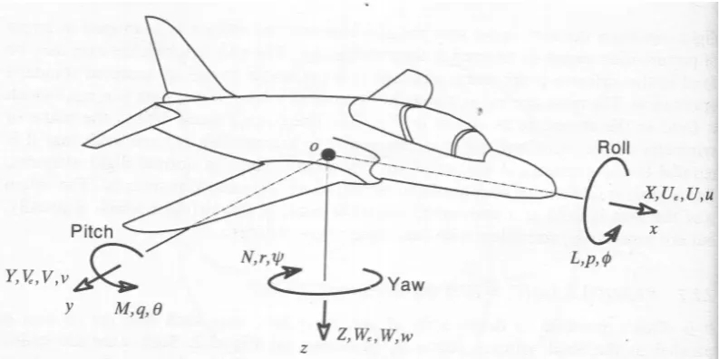
Figure 2.1: Definition of flight axes and variables (Cook 1997)
Cook (1997) denotes the axes and control surface deflections as follows (see figure 2.1). The roll orxaxis can be seen passing from the centre of gravity through the nose of the aircraft. Rotation about this axis will cause one wing of the aircraft to move upwards and the other downwards. The angle of the wings is expressed as the roll angleφ, with a positive roll being to the right. The corresponding roll rate is expressed as the value
p.
The pitch or y axis is the one passing from the centre of gravity through the right hand wing tip. Positive rotation about this axis will result in the nose of the aircraft pointing upwards and the tail of the aircraft downwards. This pitch angle is assigned the variableθ and pitch rate q.
2.2 Flight Dynamics 9
side of the aircraft.
2.2.2 Flight axis control
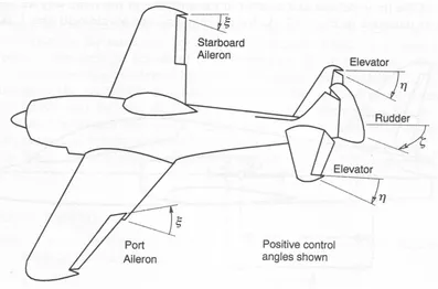
[image:24.595.122.519.256.518.2]In a four axis aircraft, these flight axes are controlled by ailerons, elevators and a rudder. The fourth axis refers to the forward motion from the motor and propeller. A four axis aircraft with these control surfaces labelled is shown in figure 2.2.
Figure 2.2: Control surfaces of a four axis aircraft (Cook 1997)
Note that a positive displacement ξ on the ailerons means the left aileron will move upwards and the right aileron downwards. This will effect a negative roll rate p and hence a negative roll angleφ.
Similarly, a positive elevator deflection η pushes the elevator towards the ground, re-sulting in a negative pitch rateq and hence negative pitchθ.
2.2 Flight Dynamics 10
[image:25.595.120.520.344.622.2]It is possible to control the aircraft using only three control axes. In this case the ailerons are removed or left fixed, leaving the elevator, rudder and throttle as the three control axes. The pitch axis control operates in the same manner as that for four axis control. The yaw and roll axes however are both controlled by the rudder. Although the rudder primarily controls yaw, it also affects the roll of the aircraft. For example, consider the application of some negative rudder. The aircraft will turn about the yaw axis at a positive rateq. This will make the left wing of the aircraft move through the air faster that the right wing. This increase in air speed will result in an increased lift on the left wing and hence a positive roll moment. This control method, although less elegant and aggressive that four axis control is more than suitable for the control of small aircraft. Indeed, many ultralight aircraft also use this method for control.
2.2 Flight Dynamics 11
2.2.3 Equations of motion
In order to undertake a numerical analysis of the flight dynamics, Cook (1997) outlines the derivation of the equations of flight for a standard four axis aircraft. These equations are formulated by considering Newton’s second law. In terms of force this is expressed as F = ma and in terms of moment or torque, M = Idωdt. That is, the sum of all forces acting on the aircraft F is equal to its massm multiplied by its acceleration a
and the sum of all moments acting on the aircraftM is equal to its moment of inertia
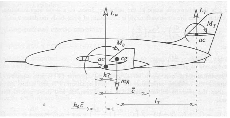
[image:26.595.122.523.389.595.2]I multiplied by its angular acceleration dωdt. With the mass and moment of inertia of the aircraft known1, for a given applied force and moment the linear and angular acceleration of the aircraft can be determined. Integrating these values of acceleration will yield the relevant velocities and displacements. An image of the pitching moment model is presented in figure 2.4.
Figure 2.4: Pitching moment model (Cook 1997)
Without wishing to go into too much detail, the equations for force and moment can be derived based on the aerodynamic properties of the aircraft and combined with the equations of motion to give a set of differential equations describing the dynamics of the aircraft. These equations can also be linearised to simplify their solution.
1
2.2 Flight Dynamics 12
The difficulty with this approach lies in a couple of areas. Firstly, determining the aerodynamic characteristics of an airframe in order to calculate applied forces and mo-ments is not a trivial task. A significant amount of analysis, using a wind tunnel or Computational Fluid Dynamics (CFD) techniques would be required to obtain realis-tic aerodynamic coefficients. Secondly, the flight dynamics of an aircraft are inherently non-linear. As such the linearised equations of motion can only provide realistic re-sults for small perturbations around the steady state. Indeed Cook (1997) refers to the equations as the ‘small perturbation equations of motion’. Given the very large dis-placements the UAV is likely to be subjected to given its small weight and low airspeed, this detailed analysis approach is unlikely to warrant the effort required to pursue it. Nevertheless, the linearised flight equations do provide insight into the flight charac-teristics of an aircraft and at the very least may be used to inform some less detailed or qualitative analysis of the UAV.
2.2.4 Significant aerodynamic effects
Although numerical analysis of the aerodynamics of the airframe will not be undertaken, consideration must be given to the major aerodynamic effects that will be encountered in flight.
Stability
While Cook (1997) outlines a vast array of static and dynamic stability issues, only two key concepts will be considered here. These are classified broadly as lateral stability issues, or stability about the roll axis, and longitudinal stability, or stability about the pitch axis. Specifically this will consider the ability of the airframe to ‘self-right‘ when subjected to atmospheric disturbances or other destabilising forces.
2.2 Flight Dynamics 13
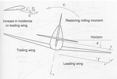
2.5. Dihedral refers to the angle of the wing above the horizontal. Consider an aircraft subjected to a small upwards draught on its left hand wing. The aircraft will roll to the right. In this position the lift on the right hand wing will act purely in the upwards direction, whereas the lift on the left hand wing will push the aircraft both upwards
[image:28.595.121.519.275.544.2]and to the right. This effect is called sideslip. As the aircraft is pushed sideways, the aircraft will yaw slightly, the angle of attack of the right hand wing will be increased and a rolling moment against the disturbance will result. In this manner the dihedral angle contributes to the ability of the aircraft to self-stabilise in the lateral axis.
Figure 2.5: Dihedral angle Γ (Cook 1997)
2.3 Method of Sensing 14
Coupling of flight axes
One case of the coupling of flight axes has already been examined in section 2.2.2 regarding three-axis control of an aircraft. That is, the tendency of the aircraft to roll due to the yawing motion of the aircraft. In a similar vein, this effect will occur in reverse; an aircraft that is in roll will tend to yaw as well. This yaw is caused by the sideslip effect already discussed in section 2.2.4. This yawing effect will be considered later as a method of detecting an error in the attitude detection system.
2.3
Method of Sensing
2.3.1 Infrared horizon detection
2.3 Method of Sensing 15
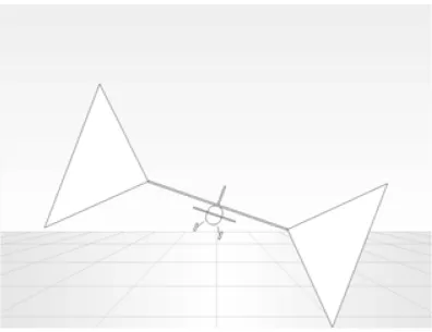
[image:30.595.122.519.112.417.2]weight savings as well as simpler hardware than other methods as advantages.
Figure 2.6: Thermopile sensor configuration for detecting the roll angle of an aircraft (Taylor et al. 2003)
The effectiveness of this approach relies on some assumptions. Egan & Taylor (2007) discusses in detail some of the characteristics of infrared thermopile sensors pertaining to their use in UAV control systems. One critical assumption used in Taylor et al. (2003) is that the sensor window is a square shape and so the angle of the aircraft can be calculated directly from the average temperature across the sensor. This is evident in the formula presented for the calculation of an absolute roll angle.
Tavg =
θsky×Tsky+θground×Tground
θtotal
(2.1)
Knowing the average temperature over the sensorTavg and knowing thatθsky+θground =
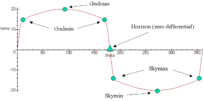
2.3 Method of Sensing 16
[image:31.595.127.483.143.320.2](2007) found that the temperature/angle was not linear and could be better modelled by a modified sine curve. This improved model is illustrated in figure 2.7.
Figure 2.7: Revised model of temperature relative to roll angle for infrared thermopile sensors (Egan & Taylor 2007)
Although this revised model does provide a better estimation of attitude, the results of Taylor et al. (2003) do indicate that the simplified approach is more than adequate for aircraft control.
2.3 Method of Sensing 17
or flag to the operator that manual control is required to fly the aircraft out of the cloudy conditions. It should be noted that flying into the cloud in the first place would be a breach of the Civil Aviation Safety Regulations. The offence regarding the flight into cloud or in non VMC conditions is one of ‘strict liability’ meaning that regardless of the intent of the operator, changes in conditions or other factors,any unauthorised flight into cloud is an offence and must be prevented by adequate flight planning and procedures in the first instance.
Note that the actual performance of the control system outside of VMC cannot be determined as non VMC flights of UAV’s have been prohibited (CASA 2003).
2.3.2 Inertial measurement
An alternative approach to determine the UAV’s attitude is by using a combination of gyroscopes, magnetometers and accelerometers. These components are combined to form an Inertial Measurement Unit (IMU) responsible for detecting the attitude and heading of the aircraft. These systems are available as proprietary modules (Iscold et al. 2010, Mendelow, Muir, Boshielo & Robertson 2007) or custom built designs (Adiprawita et al. 2007a). Egan & Taylor (2006) contends that although an inertial measurement approach has previously been the default option for flight control, it is not necessarily an appropriate solution for small UAV’s. The low mass of small UAV’s means that they are particularly vulnerable to turbulence. Importantly, “[if] for any reason the aircraft adopts a vertical flight attitude, computational singularities can lead to computed pitch/roll angles which are 180◦ in error” (Egan & Taylor 2006).
2.3 Method of Sensing 18
susceptibility of the sensors to noise is also greater than that of the thermopiles and as such a more comprehensive and robust filtering approach is required. Finally, the challenge of combining information from a range of different sensors requires more complex computations, typically in the form of a Kalman filter, and hence greater processing capability on board.
2.3.3 Navigation
All of the publications previously discussed use a GPS receiver to determine the latitude and longitude of the UAV. The GPS receiver is also used to detect the heading of the aircraft by comparing its current position with its position in previous updates. This data is fed into the UAV’s navigation system to determine flight paths. It is important to note that the reliance on this differential approach means that when the aircraft is not moving, such as prior to take off, the direction it is facing can not be determined. This is also an inherent difficulty in rotary wing platforms that, during hover, will not be moving relative to the earth.
Typical refresh times for small GPS receivers are in the order of 1 to 5 Hz, inadequate for firm control of the UAV. To combat this, the yaw gyroscope already installed to detect attitude reading errors can be co opted to provide extrapolated headings between updates (Egan & Cooper 2006).
2.4 Servo Motor Control 19
2.4
Servo Motor Control
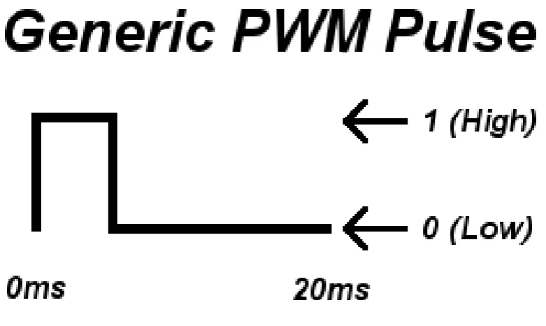
Although there are a range of methods for controlling servo motors, only one method will be considered here. This method is known as Pulse Position Modulation, or PPM. In actual fact, both pulse position and pulse width affect the control of the servo. Endurance RC (2010) gives an introduction to this process as it applies to remote control servo motors.
[image:34.595.125.516.386.619.2]Each servo will have a neutral position, typically labelled as its 0◦ position. Sending a 1.5 mS pulse to the servo control line will command the servo to hold this neutral position. This pulse is typically applied to the control line every 20 mS, a consideration that will be examined in more detail later. This is typical of all analogue servo motors in the remote control arena.
Figure 2.8: Servo motor control signal pulse (Endurance RC 2010)
2.4 Servo Motor Control 20
(nominal). The true duration of these pulse widths is dependent on the manufacturer of the servo motor. For example the minimum pulse width is as low as 0.5 mS on some common brands of remote control servo motor. This component of the signal is known as Pulse Width Modulation (PWM) i.e., the servo position is encoded as a function of the pulse width of the signal.
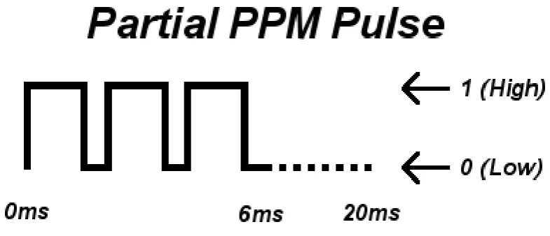
As has already been mentioned, the time between pulses for a single servo is 20 mS. This value is also only nominal and is not particularly important to the operation of the servo. Endurance RC (2010) indicates that being anywhere within a few milliseconds of this value is precise enough. The reason for this delay is a crucial one. One radio signal is required to control a number of servos. For a standard four-axis aircraft, four servo control signals are required. Any additional features added to the aircraft could increase the required number of signals to six or even eight channels. Figure
[image:35.595.123.516.498.667.2]?? illustrates how this signal can be expanded to control a number of servos. In this example, the first pulse width corresponds to the first servo channel, the second pulse width to the second servo and so on. With a nominal time between pulses of 20 mS per servo, up to ten 2 mS pulses can be delivered via this PPM scheme. As such, 10 channels is the nominal channel limit for this method of servo control.
Figure 2.9: Using Pulse Position Modulation (PPM) to multiplex the servo control signals (Endurance RC 2010)
partic-2.5 Control Methodology 21
ularly to the fly-by-wire control mode of the UAV.
2.5
Control Methodology
All of the literature discussed to this point uses PID loops to facilitate flight control. Neural networks and fuzzy control methods such as those described in Puttige & Ana-vatti (2008) and Kurnaz, Kaynak & Konako˘glu (2007) have been discounted due the the significant processing overheads and the time required to develop and train a functional controller.
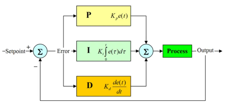
Nise (2008) gives a good explanation of the fundamental principles of PID control. PID stands for Proportional, Integral and Derivative, giving some indication as to the operation of this control method. A diagram of a typical PID loop is shown in figure 2.10. The summing junction in the control loop calculates the instantaneous error as given by the difference between the current output subtracted from the desired output. This error signal is then fed into the PID element of the loop which calculates the required intervention to achieve the desired output. The proportional element of the controller effects a response that is proportional to the error i.e., a larger error results in a larger response. In the time domain,g(t) =KP·e(t), whereKP is the proportional gain term. The derivative term delivers a response proportional to the rate of change of the error. That is, g(t) = KD· de(t)dt . Finally, the integral term delivers a response proportional to the sum of all previous errors, or g(t) = KI ·
Rt
0 e(t)dt. When all of these feedback terms are combined, the mathematical representation of the controller is as shown in equation 2.2.
g(t) =KP ·e(t) +KI·
Z t
0
e(t)dt+KD·
de(t)
dt (2.2)
2.5 Control Methodology 22
Figure 2.10: Basic PID control loop structure (SilverStar 2006)
in the way these have been implemented. Control systems can consist of a basic PID structure (Taylor et al. 2003) or include an array of feed forward paths to ensure appropriate control is applied during all flight conditions (Iscold et al. 2010). Figure 2.11 shows a comparison of the two different approaches.
[image:37.595.140.411.438.677.2]2.5 Control Methodology 23
Regardless of the detailed design of the control loops, no solution will be functional without appropriate tuning. Although detailed simulations and system identification can be undertaken (Johnson & Fontaine 2001), Egan, Cooper & Taylor (2004) advocates the use of in flight auto tuning using the Ziegler-Nichols method. The primary reason given is that the behaviour of small aircraft is particularly difficult to simulate reliably. Note that this relies on the aircraft using electric powered propulsion so that the mass of the UAV does not change with fuel consumption (Egan et al. 2004). If the UAV is to be powered by an internal combustion engine and the fuel tank is sufficiently removed from the aircraft’s centre of mass the moments acting in the longitudinal flight axis could change significantly. This effect can be mitigated by the integral control term in the control system but this could result in the UAV having less capacity to respond to disturbances of flight.
Nise (2008) also gives a more detailed explanation of the Ziegler-Nichols tuning ap-proach. The first step is to set all gains to zero and then increaseKP until the output begins to oscillate. The gain at which the output oscillates is calledKU or the ultimate gain, and the period of the oscillationTU. The values forKP,KI andKD can then be calculated according to table 2.1.
KP KI KD
[image:38.595.197.442.501.544.2]PID Coefficients 0.65·KU 0.5·TU 0.12·TU
Table 2.1: Ziegler-Nichols tuning coefficient calculation (Nise 2008)
2.6 Conclusion 24
2.6
Conclusion
Chapter 3
Legislation and Standards
3.1
Introduction
This chapter seeks to identify and examine any legislation applicable to UAV operations within Australia. Consideration is also given to any standards or common industry practises to identify any safety improvements that could be achieved in addition to complying with legislative requirements.
3.2
Civil Aviation Safety Regulations
Civil Aviation Safety Regulations (CASR) 1998 is the governing piece of federal legisla-tion for all civil avialegisla-tion activities. Part 101 Unmanned aircraft and rocket operations
3.2 Civil Aviation Safety Regulations 26
applying for the relevant exemptions and approvals from CASA, this is not considered necessary at this stage of the project. Note also that this is only a summary. Part 101
must be read as a whole by any person considering undertaking UAV operations of any sort.
Area of operation
With regard to the area the UAV may be operated, a number of considerations are relevant. This area must be:
• Outside of any prohibited or restricted area (subject to Airspace Regulations
2007)
• Outside of controlled airspace
• Below 400ft Above Ground Level (AGL)
• Not over a populous area
• In an area such that aircraft are not obstructed from approaching or landing at an aerodrome
Weather and time of day
The UAV must not be operated in the following conditions:
• In or into cloud
• At night
3.3 Other Legislation 27
Aircraft specific regulations
InSubpart 101.F UAVs, CASA makes clear the difference between a small UAV and a model aircraft. That is:
There is no practicable distinction between a small UAV and a model air-craft except that of use - model airair-craft are flown only for the sport of flying them.
Given that the express purpose of this aircraft is for research and although the parent vehicle is in fact a model aircraft, this system must be considered a ‘UAV’ as defined inPart 101 and hence is subject to all of the regulations of Subpart 101.F UAVs. As such the relevant considerations are:
• The UAV must be an aeroplane of less than 150 kg in weight or a rotary wing
aircraft of less that 100 kg in weight1
• The UAV stays more that 30m away from people not directly associated with its operation
Most of the rest ofPart 101 deals with certification and other requirements not required for a small, non-commercial UAV and as such will not be detailed in this dissertation.
3.3
Other Legislation
National parks or other reserves may also pose some restriction to flight activities and these must be assessed on a case by case basis as required. At this point no
1
It is presumed that the UAV will exceed 100g in weight and hence is not exempt from these
3.4 UAV Specific Standards 28
other legislative requirements have been identified that would apply specifically to UAV operations.
3.4
UAV Specific Standards
Some research organisations have also developed rules in addition to the requirements of the CASR. Once such example is given in Taylor & Egan (2006). This is a com-prehensive flight manual for UAV operations at Monash University. It covers many potential safety issues not directly legislated for in theCASRand should be considered prior to any extensive in-flight testing at USQ. Another example is the rules for the 2010 UAV Outback Challenge (UAV Outback Challenge 2010).
3.4.1 Monash UAV Operations Flight Manual
The Monash regulations require any UAV operator to be members of the Model Aero-nautical Association of Australia (MAAA). This has a number of advantages. Firstly, the MAAA is an approved aviation administration organisation and is responsible for controlling a number of regulations that apply to model aircraft. For example, Part 101 stipulates that:
A person may operate a model aircraft at night only in accordance with the written procedures of an approved aviation administration organisation.
Being a member of the MAAA allows for the use of the UAV under these regulations, allowing for a wider range of test conditions than would otherwise be available when flying under thePart 101 UAV regulations.
3.4 UAV Specific Standards 29
and reduces the need to find land outside of populous areas to conduct flight testing.
Taylor & Egan (2006) also outlines a range of Occupational Health and Safety (OHS) regulations specific to Monash university. While these considerations are not directly relevant, USQ does have equivalent Workplace Health and Safety policies and proce-dures and these must be considered at all times.
The operations manual also imposes a range of additional requirements. These include the fitting of a Flight Termination System (FTS) allowing a flight to be manually ended. Egan et al. (2004) describes this FTS in more detail. If the radio control signal is lost for a duration of 2.5 s, the aircraft will release a parachute. This parachute deployment also physically breaks the power connection to the motor, preventing the UAV from ‘running away’. Egan et al. (2004) also discusses potential future developments for the FTS. For example, on long range flights the UAV will move out of the range of the standard remote control. For this reason a ‘low power VHF beacon’ will be developed to provide the dead-man signal to the aircraft and it will be the loss of this VHF signal that will result in the FTS deploying. Crucially, the FTS is not designed to protect the aircraft from damage and deployment of the FTS is likely to result in significant damage to the UAV.
Some of the other requirements include restrictions on weight additional to those out-lined inPart 101 and specific limitations on propulsion methods.
3.4 UAV Specific Standards 30
Safety Officer
The safety officer is responsible for ensuring that appropriate safety equipment such as fire extinguishers, a first aid kit, mobile telephone etc. are available on site. The safety officer is also responsible for ensuring compliance with a range of regulations regarding issues such as site layout, and Personal Protective Equipment (PPE). The safety officer is also responsible for formal reporting of safety breaches and incidents.
Duty Pilot
The duty pilot is responsible for controlling all flight operations. The duty pilots re-sponsibilities include spectrum management to ensure that there is no radio interference between UAV’s. They also control the timing and sequence of flights and are respon-sible for a range of record keeping requirements imposed by the Monash UAV research group.
3.4.2 UAV Outback Challenge 2010
UAV Outback Challenge (2010) also requires pilots to be ‘MAAA gold-wing standard or equivalent’. Equivalency is determined by a number of proficiency tests for those participants who are not MAAA members.
Prior to taking part in the UAV Outback Challenge a number of safety checks are required. These include an inspection and demonstration of operation of all critical components in the aircraft, followed by a demonstration flight.
3.5 Conclusion 31
the UAV must operate on different frequencies. A UAV operating with a 900 MHz data link, 5.8 GHz video link and 2.4 GHz radio control link is given as an example of an acceptable solution for use in the competition.
There are a range of rules concerning the handling of in flight failures and emergencies. Firstly, it must be possible for the UAV operator to override the UAV control system if required. Some further action must be taken in the event that any one of a number of failure conditions are met. These conditions include the aircraft moving outside of the mission boundary, losing data or GPS connections or if the judges deem the aircraft to be ‘out of control’. If GPS, radio or data connections are lost, two options for flight termination are available. The first is for the aircraft to automatically return to a ‘comms hold’ rally point in order to regain communication. In the event that communication is not regained the aircraft can return to the airfield in a further attempt to regain the communication link. Continued failure to regain communications means that the operator is then required to terminate the flight. A number of other failure conditions and their associated control procedures are included but they are primarily variations of the return to way point method already described. If all safety systems ultimately fail or the aircraft breaches the mission boundary, the aircraft must enter the flight termination mode and return to the ground. This can be via a parachute as already described or by deliberately ‘ditching’ the aircraft.
3.5
Conclusion
3.5 Conclusion 32
Chapter 4
Methodology and Prototype
System Design
4.1
Introduction
This chapter will outline the methodology used throughout the project including the processes used for the system design, detailed design, evaluation and testing. The system design process will then be examined in more detail, looking at the criteria for major components and how they were selected. The major components considered are the parent vehicle, including supporting components such as the remote control, and the microcontroller and associated development system.
4.2
Methodology
4.3 System Topology 34
were also defined in this step in order to assist in the evaluation and testing stage.
The detailed design phase primarily considered the control system as no significant modifications to the parent vehicle were required. The control system includes both the hardware and the software required to control the aircraft. Having already selected the microprocessor for the control system in the system design stage, hardware design was related primarily to the supporting circuitry required for the control handover process as well as the method of interfacing the remote control receiver, attitude sensors and servo motors. Once this hardware was designed and constructed the final step in the process was to write the software.
During the evaluation and testing stage of the project, a number of distinct elements are under inspection. Firstly, it must be established that the element being tested performs as it was designed to. Secondly, in must be ensured that the element under inspection interacts appropriately with other subsystems in the UAV. Finally, it must be confirmed that the design concept is appropriate to the UAV. In other words, is the chosen approach a suitable way of addressing the problem at hand or are there more appropriate methods of performing the same task. Following this process will ensure that the UAV solution addresses the ultimate design intent as well as simply being free of bugs or errors.
Once all of the conceptual and design issues are addressed extensive flight testing can commence, with the intent of both tuning the control system for autonomous flight and further evaluating the performance of the UAV.
4.3
System Topology
4.4 Parent Vehicle Selection 35
These are the parent vehicle and the control system. Future development of the UAV beyond this project will see this expand as payloads such as imaging modules would be added at this level.
The parent vehicle subsystem consists of a number of major components. These are the airframe itself, the motor, speed controller and propeller, the remote control system, servo motors and batteries. All of these components will be purchased off the shelf if available and suited to the UAV application.
The other main element to the UAV is the control system. Broadly speaking this can be separated into hardware and software subsystems. The hardware elements will in-clude the microcontroller(s) and any required supporting hardware, sensors, interfacing and handover control. The software components will overlap these areas. Important modules will be the reading of remote control signals, control of servo motors, handover control, reading of sensors and the control loop itself.
This system is depicted as a flowchart in figure 4.1.
4.4
Parent Vehicle Selection
4.4 Parent Vehicle Selection 36
Figure 4.1: UAV system topology
horizontal space to achieve a reasonable height to urban obstacles such as trees and buildings. Due to this it was decided to use a fixed wing aircraft for the development of the UAV.
To aid in selecting the parent vehicle a set of selection criteria was developed. Each candidate aircraft was then assessed according to these criteria and given a ranking which ultimately determined the vehicle chosen.
4.4 Parent Vehicle Selection 37
a fast and relatively cheap solution.
4.4.1 Selection criteria
Stability
The stability of the parent vehicle was of prime concern. Having an aircraft that is stable in flight decreases the workload on the flight controller, requiring less interventions to correct aircraft attitude. Also, having some degree of self correction such as that provided by the dihedral angle means that the control system is not required to make harsh corrections as it is given some assistance by the airframe itself.
Propulsion
Consideration of the aircraft’s propulsion system involved two major components. Firstly, whether the aircraft is powered by an electric motor or internal combustion engine and secondly, the configuration of the propeller.
Although an internal combustion engine allows for greater flight times, the use of fuel brings the added complexity of having the mass of the aircraft change throughout the flight as it is consumed. This in turn affects the tuning of the control system and some compensation may be necessary. On the other hand use of an electric motor resolves this issue but the batteries used for power do have a lower energy density that fuel based systems.
4.4 Parent Vehicle Selection 38
Gliding characteristics
The ability of the parent aircraft to glide was considered to be an important charac-teristic in terms of the selection process. This gliding ability allows for the reduction of throttle during flight to extend aircraft range. Importantly, it also suggests that the aircraft is less likely to plummet to the ground in the event of a loss of power or other similar event.
Payload capacity
Although important, the payload capacity was not considered as a critical factor in the selection process. The expected weight of any flight stabilisation controller is minimal and at this stage no cameras or other heavy equipment were to be fitted to the aircraft. Information regarding the payload capacity of the aircraft was also particularly difficult to find and hence a qualitative assessment of the payload capacities was undertaken after speaking with experienced model aircraft pilots.
Payload capacity also included a consideration of the space available to install extra electronics, batteries and any other components that may be required.
Ease of control
4.4 Parent Vehicle Selection 39
Ease of modification
Although significant modifications to the airframe were not expected to be required, the ability to easily fit control circuitry and sensors to the aircraft was important.
Durability
The durability of the aircraft was a key factor in the selection process. Although failure resulting in a crash landing was not considered to be likely, even a hard landing could result in significant damage to the aircraft and added components. The primary con-struction methods for off the shelf aircraft were a ply/balsa combination or Expanded Poly-Propylene (EPP) foam. EPP foam is far more resistant to damage and as such is favoured over the ply/balsa combination.
Cost
The cost of the aircraft system was not used as part of the ranking process as such. Rather, the focus was on selecting the ‘right’ system in terms of the other selection criteria, with the condition that the parent vehicle and all supporting components such as remote controls, batteries etc. should be under $1000.
4.4.2 Aircraft details
4.4 Parent Vehicle Selection 40
[image:55.595.120.520.137.380.2]On considering all of the criteria already discussed, the Multiplex EasyStar is the preferred option and hence has been chosen as the parent vehicle for the UAV.
Figure 4.2: Multiplex EasyStar remote control foam glider (shown with control system fitted)
4.4.3 Additional components
After selecting the parent vehicle a range of additional components needed to be chosen. The Multiplex EasyStar kit includes a number of these including the motor, propeller and speed controller. Other components that were not included were the remote control system, batteries and servo motors.
Remote control
4.4 Parent Vehicle Selection 41
The aircraft itself requires three channels for control of the rudder, elevator and throttle. An extra channel is required to switch control from manual to stabilisation mode.
After considering a number of available remote controls, the Spektrum DX6i was chosen. This is a 6 channel remote control system, allowing for control of a four-axis aircraft with a control hand over switch and one auxiliary channel. As the EasyStar glider only requires three channels for manual control, any input from the aileron stick can simply be ignored.
[image:56.595.121.520.350.677.2]A further advantage of the chosen remote control is that receivers can be bound to a specific transmitter, meaning that in situations where a number of aircraft may be in operation, remote control signals should not interfere with each other.
4.4 Parent Vehicle Selection 42
Batteries
[image:57.595.121.524.321.677.2]Having chosen an electric motor as the propulsion system for the UAV, a battery or batteries must also be selected. The most common types of battery for remote control aircraft are Nickle Metal Hydride (NiMH), Nickle Cadmium (NiCd) and Lithium Polymer (LiPo). Of the three, Lithium Polymer batteries provide the greatest energy density and as such were chosen for use in this UAV. The actual model of battery chosen was a Turnigy Power Systems 3 cell 2200 mAh High Discharge Li-Po Battery. This battery is of the appropriate voltage for the Multiplex motor and at 2200 mAh should allow for reasonable flight times.
4.5 Development Platform 43
Servo Motors
The selection of servo motors was primarily dictated by the available space in the EasyStar glider. Two HiTec HS-81 servo motors were selected. These motors weight 16 g, which is the size of the general class of servo motors that the EasyStar glider was intended to be fitted with. The pulse width required to control these servos is 0.6 mS to 2.4 mS, significantly wider than the nominal 1 mS to 2 mS standard. Although a device called a servo stretcher can be fitted to allow these servos to interface with standard control signals, the customised nature of the control system means that this can be allowed for in software instead.
4.5
Development Platform
At the outset of the project the MikroElektronika EasyPIC5 development platform was made available by USQ for the purposes of this project. This development platform is made up of two components. Firstly, the EasyPIC5, which is the hardware compo-nent of the development system. The EasyPIC5 board contains all of the supporting hardware required to run the PIC Processor itself. This includes the power supply and oscillator. The development board also has a number of extra features useful for the testing and development of PIC software. This includes an in-circuit programmer and debugger, LED’s for displaying port outputs, switches for generating inputs, poten-tiometers connected to analogue to digital converter pins, alpha-numeric and graphical LCD displays and expansion headers for connecting other hardware. A range of add on modules are also available to expand the already extensive capabilities of the devel-opment system. This wide range of functionality makes the EasyPIC5 board a good choice for development of the UAV system.
4.5 Development Platform 44
Figure 4.5: HiTec HS-81 servo motor
4.6 Microcontroller Selection 45
Figure 4.6: MikroElektronika EasyPIC5 Development Board
4.6
Microcontroller Selection
4.6 Microcontroller Selection 46
[image:61.595.121.520.104.394.2]PIC processor.
Figure 4.7: PIC16F887 internal block diagram (Verle 2008)
Some of the key features of the PIC16F887 processor are:
• Clock Speed The maximum clock speed of the processor is 20 MHz, towards
the upper end of processors in this range. This will allow for fast computation of the control loops ensuring that servo signals can be updated within 20 mS.
• IO Pins35 Input/Output pins are available on the chip (although some of these pins serve multiple purposes), allowing for plenty of expansion of the UAV hard-ware. This will be particularly useful during further development of the UAV when the integration of electronic payloads may be necessary.
• Analogue Inputs Analogue inputs are required for most of the UAV sensors.
4.6 Microcontroller Selection 47
• Timer ModulesThe availability of timers is crucial to the decoding and
encod-ing of PPM/PWM signals as well as to the operation of the control loop.
• Serial CommunicationsSerial communications is not likely to be required for this phase of the project but will allow for communication between the processor and external modules via the I2C or SPI bus.
[image:62.595.121.521.308.613.2]• In-Circuit Serial Programming The ability to program the processor in-circuit means that modifications can be made to the software throughout the development and testing process with ease.
4.7 Conclusion 48
4.7
Conclusion
Chapter 5
Detailed Design
5.1
Introduction
This chapter will outline the detailed design of the UAV project. As the parent vehicle has been constructed using purely off-the-shelf components, consideration is only given to the control system. Firstly the hardware design is examined, looking primarily at the methods of interfacing with key subsystems and the approach to handling the switch of control from manual to automatic mode. Secondly the design of the control system software is considered, looking at the key routines within the software and how these are integrated to form both the stabilisation mode and fly-by-wire mode software.
5.2
Control System Hardware
5.2 Control System Hardware 51
[image:66.595.147.499.161.343.2]detail below. Schematics of the entire system are included for reference in appendix B.
Figure 5.1: Hardware system block diagram
5.2.1 Sensor interface
5.2 Control System Hardware 52
Figure 5.2: Infra-red thermopile sensor boards
5.2.2 Control input
5.2 Control System Hardware 53
5.2.3 Failsafe control handover
The failsafe control handover sub-system is centred around a 4016 CMOS bi-lateral switch. During manual operation the switches in the 4016 IC are turned on by the handover signal from the remote control. In this state, the servo control signals are passed directly through the 4016 to the servos themselves. Once the handover signal changes the switches are all turned off, stopping any signals reaching the servos directly from the receiver.
As well as switching the 4016 IC, the handover signal alerts the PIC processor that it is now in control of the aircraft and it begins processing sensor information and sending the calculated control signals to the servos. This signal arrives at the PIC via the pin RB2.
Importantly, the PIC processor is not controlling the handover process itself so control can be regained in the event of a processor brown out or other fault causing the processor to fail.
5.2.4 Attitude controller
The attitude controller itself is based around the PIC16F887 microprocessor. For the development of the control system, the EasyPIC5 development board from Mikroelek-tronika has been used, containing all supporting hardware required for the operation of the PIC. Other hardware was built on a veroboard and connected to the EasyPIC development system via ribbon cables, as shown in figure 5.3.
5.3 Control System Software 54
Figure 5.3: EasyPIC5 development board and UAV hardware prototype
5.2.5 Microcontroller Support Hardware
The support hardware required for the microcontroller is actually located on the EasyPIC5 board. This includes the power supply, reset circuit and oscillator. These components have been included on the schematic as they will ultimately have to be replicated in hardware once the control system is implemented as a Printed Circuit Board (PCB). The design for these components has been adapted from the PIC data sheet to suit the requirements of the UAV.
5.3
Control System Software
de-5.3 Control System Software 55
gree of freedom model, describing the rigid body dynamics of the aircraft in terms of aerodynamic conditions. These models are combined with an atmospheric model such that the flight of the aircraft can then be simulated. Using the simulation the PID gains of the aircraft’s control loops can be tuned prior to flight.
The other method of control system development is characterised by the work in Egan et al. (2004). In this method, the control system is designed to give separate control loops in the pitch and roll flight axes. Instead of creating a model for simulation of the aircraft, the control system is implemented in hardware and installed in the aircraft. Tuning of the control loops then occurs in flight. Egan et al. (2004) used the tried and tested Ziegler-Nichols tuning method, implementing this as an in-flight automated tuning function.
On consideration of the two approaches, the latter is favoured for a few reasons. Firstly, the significant overhead required to measure the aerodynamic coefficients used in the aerodynamic model of the aircraft puts this approach out of the reach of this project. Also if this work was to be completed, all results would be specific to the current parent vehicle and any significant changes to the airframe or the installation of the control system in a new aircraft would require all of this work to be re-done. Finally, the flight equations used in the aerodynamic model are linearised and only hold true for small perturbations around the steady state. As such the accuracy (or inaccuracy) of the model means that tuning the PID gains in the simulation is not likely to yield results good enough to warrant the effort.
5.3.1 Control system design
The control system is shown in figure 5.4 and 5.5 in block diagram format. Note that the pitch and roll axes are not coupled and operate independently of each other.
5.3 Control System Software 56
Figure 5.4: Control system block diagram (stabilisation mode)
is for the UAV operating in stabilisation mode. When enabled, the flight controller reads the attitudinal information from the infra-red thermopile sensors and calculates the required servo outputs based on a target attitude of 0◦ (level in both the pitch and the roll axes).
5.3 Control System Software 57
Figure 5.5: Control system block diagram (fly-by-wire mode)
For simplicity, roll angles are set by the aileron axis on the remote control rather than the rudder axis, with pitch set by the elevator axis. The reason for this is that aileron and elevator control both use the same joystick, so full control of the aircraft can be achieved using only one joystick. This greatly simplifies flying the aircraft and means that very little training will be required to control the UAV.
5.3.2 Attitude detection
5.3 Control System Software 58
system will refer to the z-axis sensor to determine the attitude. In co-pilot mode the joystick can be used to demand a difference of up to this maximum value.
In practice the demanded pitch and roll angles will be limited to a value less than this maximum. For example, if the field of vision of each thermopile is 100◦ it is able to measure pitch and roll angles of±50◦. For this reason the maximum demanded pitch and roll angles should be limited to some value less than this. Although the z-axis sensor could be used to fly outside of these limits a more conservative approach is considered to be favourable, particularly during testing.
In the software the calibration function is performed by the calibrate() routine. This reads the value seen by RA2 and stores it as max error. At this stage calibration is only undertaken at the start of each flight but in-flight calibration can be included at a later stage if the duration of the UAV’s flight is extended such that it will fly over an extended part of the day.
5.3.3 Control decoding
Control signals from the remote control receiver arrive at the PIC processor in the form of Pulse Width Modulated (PWM) waveforms. A pulse width of 1.5ms corresponds to the neutral or 90◦position of the servo i.e., no control surface deflection. Decreasing the pulse width to 0.6ms will move the servo to the 0◦ or minimum position, and increasing the pulse width to 2.4ms will move the servo to the 180◦ or maximum position.
5.3 Control System Software 59
one servo pulse will arrive at the processor at a time and so only one timer is required. This greatly simplifies the process of decoding servo signals.
The two variables that store the read control inputs are aileron width and eleva-tor width. Remember that although the aircraft does not have ailerons, the aileron channel is used as it shares the elevator joystick on the remote control. This greatly simplifies the task of the UAV operator.
5.3.4 Stabilisation controller
The stabilisation controller is simply the software implementation of the control loop described in section 5.3.1. The differential signals as measured by the ADC module are used as the error input to the control loop. This error value is offset by the aileron and elevator inputs in the fly-by-wire mode to achieve co-pilot control.
The gains for the PID control routine are set in the software before loading onto the aircraft. Proportional, integral and derivative gains must be set separately for the pitch and roll axes as the control loops are not coupled.
The mathematics used in the stabilisation controller are derived from the digital PID implementation presented in Charais & Lourens (2004). That is:
C(n) =KpE(n) +KiTs n
X
0
E(n) +Kd
E(n)−E(n−1)
Ts
(5.1)
5.3.5 Servo control output
5.4 Conclusion 60
not able to handle variable delay times so an alternative approach had to be found.
Vdelay mscan accept variable delays but only as whole numbers of milliseconds so was unsuitable. Instead theDelay Cyc command was used. This function accepts a value of ‘tens of CPU cycles’ to determine the delay. For this reason the servo out function converts the delay in microseconds to tens of clock cycles. The appropriate output pin is set to 1, the delay function performed and then the output pin reset to 0. This generates the required pulse width for control of the servo motor.
5.4
Conclusion
Chapter 6
Evaluation and Testing
6.1
Introduction
This chapter will outline the process of testing the UAV. Discussion about the appro-priateness of the design as well as simply the operation of the UAV will be presented and improvements suggested where required. These suggestions will be considered for further work in the following chapter.
6.2
Attitude measurement
During initial tests of the attitude measurement system, some problems were encoun-tered measuring the pitch of the aircraft. This was due to the mounting arrangement used for the thermopile sensors. In the current arrangement the rear pitch axis sensor points directly at the electric motor. As such the temperature seen by this sensor when the motor is running is elevated, falsely indicating to the control system that this sensor is pointed more towards the ground than the front pitch axis sensor.
6.3 Control input and output 62
directly at the motor. This does however require some modification to the attitude calculation process. Previously a downwards pitch of the aircraft would result in a decrease in the output of only one axis of the sensor board. In the 45◦ orientation, both axes will exhibit an equal, lower value. Similarly, whereas a roll putting the left-hand wing of the aircraft towards the ground only decreased the value of one axis using the previous configuration, the new orientation will result in the two axes changing by the same amount but in opposite directions. By re-writing the code that calculates the attitude of the aircraft to incorporate this new mixing effect, the problem of heat generated by the motor can be resolved.
6.3
Control input and output
To verify the servo control signal encoding/decoding routines, a modified version of the control system was loaded onto the PIC microcontroller. This modified program simply read and decoded the servo signals, re-encoded the signals and output them to the servo motors. Using this testing software, the aircraft would operate as if it were under direct remote control. For example, a full down on the elevator joystick would be decoded and re-encoded as the same value. This process uncovered some minor bugs in the software program but once the appropriate changes were made, the servos moved through their full range of operation when commanded by the remote control.
6.4 Failsafe control handover 63
purely to handle the servo signal processing functions. This second processor would communicate with the main control processor via SPI or I2C b