University of Southern Queensland
Faculty of Engineering and Surveying
Initial Design of a High-Performance
and Cost-Effective Mountain Bike
A dissertation submitted by
Jiel Case
In fulfilment of the requirements of
Courses ENG4111 and ENG4112 Research Project
towards the degree of
Bachelor of Mechanical Engineering
i
Abstract
Downhill mountain biking is fast becoming popular sport in both Australia and Internationally. From the 1970‟s when people started competed this sport there has been many improvements such as brakes and better suspension designs to increase performance while also decreasing injuries.
As this sport is becoming more and more popular, there are a number of new frames and designs that are being brought out every year. Each of these of designs has their own advantages and disadvantages which will be looked at before the design process begins to design this mountain bike.
The project aims to design a downhill mountain bike that is not only a high-performance but also to be cost effective. As there are not any documents readily available that explain the design process, another aim of this project is to create a document that can be used by future students and amateur bike designers in order to give them a rough idea of where to start and what to do.
The initial design has been completed although there are a number of modifications that can be made in order to improve both the performance and cost-effectiveness. As this is only an initial design due to the fact, there has been limited analysis carried out due to the time consuming design stage. The material selection process has also been completed and aluminium alloy of grade 6061-T6 was found to be the best material for this application.
There are also a number of directions this project could be built on in the future in order to keep improving this design or use this project as a basis to design a new downhill mountain bike.
ii
University of Southern Queensland
Faculty of Engineering and Surveying
ENG4111 Research Project Part 1 &
ENG4112 Research Project Part 2
Limitations of Use
The Council of the University of Southern Queensland, its Faculty of Engineering and Surveying, and the staff of the University of Southern Queensland, do not accept any responsibility for the truth, accuracy or completeness of material contained within or associated with this dissertation.
Persons using all or any part of this material do so at their own risk, and not at the risk of the Council of the University of Southern Queensland, its Faculty of Engineering and Surveying or the staff of the University of Southern Queensland. This dissertation reports an educational exercise and has no purpose or validity beyond this exercise. The sole purpose of the course pair entitled “Research Project” is to contribute to the overall education within the student's chosen degree program. This document, the associated hardware, software, drawings, and other material set out in the associated appendices should not be used for any other purpose: if they are so used, it is entirely at the risk of the user.
Professor Frank Bullen Dean
iii
Certification
I certify that the ideas, designs and experimental work, results, analyses and conclusions set out in this dissertation are entirely my own effort, except where otherwise indicated and acknowledged.
I further certify that the work is original and has not been previously submitted for assessment in any other course or institution, except where specifically stated.
Student Name: Jiel Case Student Number: 0050086494
____________________________ Signature
iv
Acknowledgements
First and foremost I would like to thank my supervisor Mr Steven Goh for his guidance with throughout the year.
Table of Contents
Abstract ... i
Limitations of Use... ii
Certification ... iii
Acknowledgements ... iv
List of Figures ... v
List of Tables ... vi
1 Introduction ... 1
1.1 Project Topic ... 1
1.2 Project Background ... 1
1.3 Research Aims and Objectives ... 1
1.4 Methodology ... 2
1.5 Dissertation Overview ... 3
2 Literature Review... 5
2.1 Introduction ... 5
2.2 Mountain Biking History ... 5
2.3 Existing Mountain Bikes... 6
2.3.1 Current Designs ... 6
2.3.2 Current Materials ... 12
2.3.3 Existing Components ... 14
2.3.4 Design and Manufacture ... 17
3.0 Design and Methodology ... 21
3.1 Introduction ... 21
3.2 Design ... 21
3.2.1 Initial Design ... 21
3.2.2 Component Selection ... 28
3.2.3 Final Design ... 31
4.0 Material Selection ... 59
4.1 Introduction ... 59
4.2 Initial Material Selection... 59
Final Material ... 62
5.0 Results and Discussion ... 67
5.1 Introduction ... 67
5.2 Design Analysis ... 67
6.0 Conclusion ... 70
7.0 Recommendations ... 71
7.1 Future Work ... 71
List of References ... 73
Appendix A: Project Specification ... 76
Appendix B: Detailed Drawings ... 77
Appendix C: Material Selection Charts ... 84
v
List of Figures
Figure 1 Tubing Section Definition ... 6
Figure 2 Single Pivot Design ... 8
Figure 3 Horst Link on a Specialized Bighit ... 9
Figure 4 Lawwill Linkage ... 9
Figure 5 Faux Bar Suspension ... 10
Figure 6 VPP Design by Santa Cruz ... 11
Figure 7 Example of Butted Tubing ... 17
Figure 8 Different Types of Butted Tubing ... 18
Figure 9 Mandrel Press ... 19
Figure 10 Tube Reeling ... 19
Figure 11 Steerer Tube... 29
Figure 12 Section view of Head tube ... 32
Figure 13 Down tube ... 34
Figure 14 Split Seat Tube ... 35
Figure 15 Seat tube ... 37
Figure 16 Top Tube Length ... 38
Figure 17 Top Tube ... 39
Figure 18 Wheel Clearance ... 41
Figure 19 Chain Stay ... 41
Figure 20 Current Axle Path ... 42
Figure 21 Seat stay ... 43
Figure 22 Required Geometry with no load on rear shock ... 44
Figure 23 Linkage Length ... 45
Figure 24 Width of Linkage Plate ... 46
Figure 25 Linkage Plate ... 47
Figure 26 Hanger ... 48
Figure 27 Ball Bearing ... 50
Figure 28 Cable Routing Tab ... 51
Figure 29 Brake Mount ... 53
vi
Figure 31 Brake Mount ... 55
Figure 32 Frame without any compression of the shock ... 56
Figure 33 Frame with full compression ... 57
Figure 34 Linkage system ... 58
Figure 35 Wheel Path... 68
vi
List of Tables
Table 1 Overview of Geometry ... 12
Table 2 Analytical-Hierarchy Process for Suspension Platform ... 23
Table 3 Bearing vs. Bushing Selection ... 49
Table 4 Initial Material Selection ... 61
Table 5 Designations for alloyed wrought and casted aluminium alloys ... 63
1
1 Introduction
This chapter describes the project outline and the research objectives of the project. The primary purpose of this project is to research current mountain bikes and methods of design and then design a high-performance and cost-effective mountain.
1.1 Project Topic
Design of a high-performance and cost-effective mountain bike
1.2 Project Background
Within the last two decades, designing mountain bikes have progressed rapidly in many areas such as better suspension designs, better materials, and also better handling. Preidt (2011) also states that these advancements in technology have decreased mountain biking injuries as they allow the rider to have greater control. However there are problems that arise with these advances such as increased outlays to purchase these products.
The aim of this project is to design a mountain bike which will perform (durability and rideabilty) comparatively with existing high-performance mountain bikes. In addition, the aim of this project is to reduce the cost of manufacture. The product designed is to be cost effective against high-performance mountain bikes currently available on the market.
1.3 Research Aims and Objectives
The aim of this project as stated in the introduction is to research current mountain bike designs and then design a mountain bike to compete with current designs in both performance and cost.
The objectives of the project are outlined below:
1. Research current downhill mountain bikes that are available on the market and the environment they are used in.
2 3. Using the material selection process, decide on which material/s will be
the best for this application.
4. Model the final design and calculate forces that the frame will need to handle and analyse worst case scenarios using ANSYS.
5. Cost-analysis of the final design for materials and also manufacturing. As time permits:
6. Build a prototype and do some physical testing.
1.4 Methodology
To be able to carry out this project effectively and efficiently, a methodology is required for guidance and also to have planned deadlines. The methodology for the project is detailed here.
Review current mountain bike designs and environment
In this initial review, the current designs and materials used will be researched and analysed, while looking to see if there is another material that could be used for this application. Also the environment that the bikes are used in will be researched to better understand the type of application that the frames will be faced with.
Develop Initial Designs of the Frame
A number of initial designs will be created and critiqued using the analytical-hierarchy process to develop the final design that will be further designed.
Design of the Final Product
The design of the final product will be carried out using a 3D modelling program with the worst case scenario tested using ANSYS and calculations will be carried out to support the findings.
Material Selection Process
3
1.5 Dissertation Overview
Chapter 2 – Literature Review
This section starts by looking at the history and also what type of terrain and environment that these mountain bikes are used in. This will give a brief understanding of what type of conditions that will be designed for. From here it looks at the current designs and the advantages of each compared to one another. It will then carry on looking at current materials used and why these materials are used. Existing components that must be able to fit in my frame will be looked at and each of these components will be briefly explained. This chapter will then finish by looking at the manufacturing techniques that are used for these products.
Chapter 3 – Design
This section will first look at all the different designs and then the best design will be chosen using the analytical hierarchy process. Then the final design will be carried out and the material selection will finish this chapter.
Chapter 4- Material Selection
This chapter will look at the material selection criteria used and also go through the steps involved with this material selection. The first step will be to decide what type of material is best suited to this application before deciding what grade is the best option.
Chapter 5- Results and Discussion
This section will look at the design analysis which will be carried out using Linkage and Solidworks.
Chapter 6- Conclusions
4 Chapter 7 – Future work
This section will look at the future work which can be carried out and also suggest projects that future students can carry out in order to make a better design.
5
2 Literature Review
2.1 Introduction
Mountain biking is becoming a mainstream sport as people are realising that it is good for your health, has great social aspects and also brings back memories from when you were a child and go as fast as possible on your bicycle down a hill. After defining what mountain biking and then more specifically downhill mountain biking, current designs, components and materials will be researched.
2.2 Mountain Biking History
Mountain biking has been around for years, just not in the current form of today. Throughout the history of the bicycle there have been pioneers that have used or created a bicycle to achieve something that have not been done before. Breeze (1996) states the first bicycle to be ridden off road was in 1816, however many disagree as this bicycle does not have pedals or a chain. Many other advancements over the next 150 years lead to the current bicycle design, such as pneumatic tires in 1887, first derailleur in 1973.
Breeze (1996), states that the first timed downhill race was conducted at Fairfax, Marin County on October 21, 1976. From this day the sport of Downhill Mountain biking as progressed in small numbers to start with during the rest of the 70‟s and then during the 80‟s saw an impressive growth in numbers due to many reasons. The first production mountain bike in 1978, created the ability for many people to buy a mountain bike and take up the sport. Also quick developments in braking, gears, suspension and handling are also attributed to the progression of the sport during the 80‟s.
6
2.3 Existing Mountain Bikes
2.3.1 Current Designs
There are currently a number of different designs that are being used for downhill mountain bikes, ranging from the simple yet effective single pivot up to more complex systems such as the VPP system. This section will look at the current designs available and look at where each excels and where they don‟t.
Figure 1 shows a simplified version of a bicycle and shows a number of major sections of the frame including the headtube, top tube, down tube, seat tube, seat stays and chain stays. Also the forks are highlighted to show how they integrate with the frame. These sections will be designed in later chapters apart from the fork as an existing fork will be used.
Most downhill mountain bikes these days utilize between seven and ten inches of travel and have very specific set-ups with regards to other types of bikes. There are also many other factors that must be considered when designing a mountain bike such as the head and seat angles, wheelbase and bottom bracket height. According to Brady (2008), as long as the design is within a certain degree or distance, then there should not be any troubles however if the dimensions are outside these standard values then the bike will ride as well as it should.
7 The head angle is the angle between the head tube and the ground. Brady says that downhill mountain bikes should have a slack angle of between 66–69 degrees. The advantage of this slacker angle is better stability in technical sections and corners. The seat angle is similar to the head angle but is the angle between the seat tube and the chain stays and this angle should also be slack for a downhill bike. The slacker this angle the further the weight is over the back wheel and allows technical sections to be taken easier.
Wheel base and bottom bracket height according to Brady are also very important in that they govern how much clearance your bike has. A high bottom bracket will allow more clearance however this will raise the centre of gravity and vice versa for a low bottom bracket. The disadvantage of having a high bottom bracket is the impact on your cornering ability while if it is too low than rocks and other obstacles can easily damage this part of your bike. Wheel base is the distance between your front and rear wheel. A downhill mountain bike also requires great strength while still being light enough for great handling and be able to ride over various terrains.
8
Another type of suspension technology is four-bar linkage system. Scott (2009) states that this design was develop to improve the downfalls of single pivot frames with regards to stiffness however they come with increased weight and extra maintenance is required due to the complexity. There are four main types of four-bar linkage including Horst Link, Lawwill, Faux Bar and VPP. According to Everything Bicycling (n.d.), four-bar linkage systems will have several linkages with a pivot behind the bottom bracket, one near the rear axle and also one at the top of the seat stays.
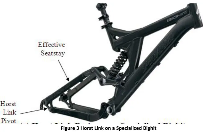
According to Everything Bicycling (n.d.), Horst Link has a pivot point in front of the rear wheel dropout as this allows the linkage components to affect the rear axle path and allow for vertical travel. An example of a four bar linkage with Horst link is shown in figure 3. The axle path for this system is very similar to that of the single pivot frame. Scott (2009) further says that the advantage of this type of frame over the single pivot is less pedal bob and also less detrimental braking effects on the frame. The problem with this type of linkage is that is patented to Specialized. The picture below shows a four-bar frame with Horst Link.
9
[image:19.595.162.490.62.276.2]The next type of four-bar linkage is the Lawwill design shown in figure 4 which according to Scott (2009) is the most advantageous of the four-bar frames in terms of axle path manipulation and brake isolation. Lakshmi (2008) states that the Lawwill design adapted the A-arm suspension design from sports car racing and was the first four bar linkage in mountain biking.
[image:19.595.88.534.417.651.2]Figure 4 Lawwill Linkage
10 Everything Bicycling (n.d) says that the Faux Bar shown in figure 5 is named as it looks similar to a four bar linkage. The Faux bar is actually a single pivot frame where the wheel path is rotated around a single point located near the bottom bracket. The main difference between the Horst linkage and the Faux setup is the location of the rear pivot with Faux bar being located above the dropout instead of in front.
[image:20.595.133.510.209.441.2]Another form of the four suspension linkage is the VPP which is illustrated in figure 6 or virtual pivot point with according Hollow (2004) to the patents currently owned by Santa Cruz bicycles with licences to Intense Cycles. VPP has many advantages over not only a single pivot design but also many of the other four bar suspension technologies. The VPP has the advantage of better pedal efficiency and also better suspension control attained through the way that the linkages work. Biker (2010) states that the VPP suspension has two different linkages rotating in opposite directions and use pedal-induced chain force to extend the suspension and therefore making the rear suspension stiffen up allowing greater pedal efficiency. An example of a VPP style frame can be seen below.
11 The next section will look at the geometry of a number of popular bikes to gather the type of geometry that the bicycle designed will need to have. All specifications will be taken at frame size that suits a person of 5‟8” to 5‟10” as this is roughly the world‟s average height according to Godbole (2010). Brady (2008) says that the important geometry for a bicycle is the head angle, seat angle and the bottom bracket height, so these will be looked along with wheel base, amount of travel and also the type of travel that is used for each individual frame.
According to Linkage (n.d.) there is another major element to the rear suspension and that is the progressivity. They state that there are three main types which are rising (progressive), falling and linear. Rising rate is where lower values of the leverage ratio mean larger travel and this generally causes the suspension to stiffen when being compressed. They further state that falling rate is the opposite and is really plush and is easier to bottom out. Linear is as the name suggests a constant ratio between the leverage ratio and the amount of travel. They say that this last type is the most desirable for downhill mountain bikes as they are repeatedly absorbing rougher terrain.
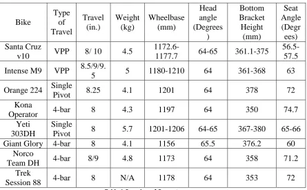
12 Table 1 Overview of Geometry
From table 1, a number of dimensions for geometry can be found to match current frames. The amount of travel that the frame requires is 8-10inches. The wheelbase for the frame is to be somewhere between 1170 and 1210mm. For the three critical dimensions of the head angle, bottom bracket height and seat angle the only one that varies majorly is the seat angle. It can be seen from the above table that head angle needs to be in the vicinity of 64 -65 degrees and the bottom bracket height needs to be at least 355mm while also staying under 375mm. The seat angle however has a wide range of angles that it could be but like Brady (2008) stated, the slacker the seat angle the better it is for downhill mountain biking so a range of between 58-70 degrees will be taken. It can also be seen that the average weight of current frames with shock included is within the five kilograms mark. A nominal shock weight according to the Fox Shox website is about 500g so the frame will need to be roughly four – five kilograms.
2.3.2 Current Materials
There are currently four main materials that are used to manufacture mountain bike frames, being steel, aluminium alloys, composites and titanium. Each has their own advantages and disadvantages with relation to the other materials. From ABC of mountain biking, „lightweight and durable is now the standard of mountain bikes. Anything else is mediocre‟ is just one example of the future of mountain biking.
Bike Type of Travel Travel (in.) Weight (kg) Wheelbase (mm) Head angle (Degrees ) Bottom Bracket Height (mm) Seat Angle (Degr ees) Santa Cruz
v10 VPP 8/ 10 4.5
1172.6-1177.7 64-65 361.1-375
56.5-57.5 Intense M9 VPP 8.5/9/9.
5 5 1180-1210 64 361-368 63
Orange 224 Single
Pivot 8.25 4.1 1201 64 378 72
Kona
Operator 4-bar 8 4.3 1197 64 350 74.7
Yeti 303DH
Single
Pivot 8 5.7 1201-1206 64-65 367-380 65-66
Giant Glory 4-bar 8 4.1 1156 65.5 376.2 60
Norco
Team DH 4-bar 8/9 4.8 1173 64 358 71.2
Trek
13 According to Brady (2008) each type of material has a purpose and also a major advantage over each of the other type of materials. He summarises the materials as follows; „Steel – the old standard, Aluminium – the newish standard, carbon fibre- the future standard and titanium as the steel of gods‟. Man (2004) states the aluminium is currently the most used material of the four listed. Man however, also states that there is no “perfect “material to build a downhill mountain bike from.
Steel
Man and Brady both agree that steel is going out of fashion due mainly due to the fact that it is relatively heavy. Although they both agree on this fact, they both state that steel has the following advantages over other materials; strong, stiff, durable and cheaper than the alternatives although it is also prone to rusting and also is a lot heavier than the other materials. The most common type of steel to be used for the manufacture of downhill mountain bikes is chrome moly as it is very strong however as common with steel, is very heavy.
Aluminium Alloys
Aluminium alloys as stated by Brady is the „newish standard‟ due to many reasons which will be looked at within this section. Man and Rich (2010) both say that aluminium is the most common due to the fact that it is lightweight and fairly affordable. ASM (2007) says that bicycle frames are built from a 6xxx series grade of aluminium in which Rich further elaborates and says that 6061 is the most common type of aluminium used. Brady and Man say that the advantages of aluminium are lightweight, affordable, high resistance to corrosion, great rigidity easy to draw into any shape and also cheap to manufacture. However both state that aluminium has the disadvantage over steel due to its lower strength and also the fact that it is harder to repair than steel. However Man says that the aluminium used must be butted to provide a good ratio between strength and weight. Butted tubing will be talked about within the manufacturing process.
Composites
14 as it would easily get damaged and therefore break and could cause serious injury. However, both Scott (2009) and Brady both say that carbon offers both a light and durable frame and also has the ability to be moulded into any shape therefore allowing manufacturers to achieve whatever look that they desire. But as said earlier, carbon does have disadvantages of being more expensive, although prices are dropping for this type of frame, they are irreparable if damage from a direct impact and also they react negatively to solvents and acids.
Titanium
Titanium as stated by Brady is the „steel of gods‟ due to how expensive the frames are. He further goes onto say, along with Rich, that titanium is a very strong material while also being fairly light. The other advantages as stated by Man of this material are that it is corrosion resistant and also very durable. Brady also states that although this material has many advantages over the other materials used it will never become the most popular due to not only how expensive it is but also the fact that it is very difficult to manufacture consistently to a high standard.
2.3.3 Existing Components
There are many different components that have to be considered when designing a mountain bike frame that must be able to be attached in the correct and proper way. The components that must be considered include:
Forks
Bottom Bracket Derailleur Seat post Rear shock Rear axle Rear brake
There are also many other factors that need to be considered which include: Cable routing
Crank Clearance Rear wheel clearance ISCG mounting
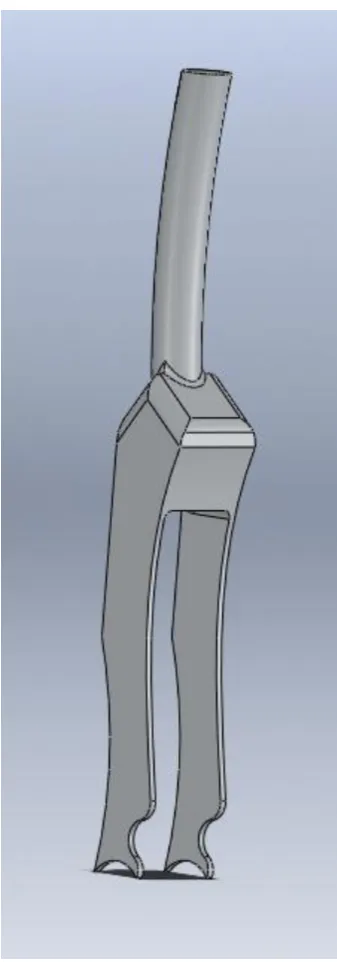
15 Forks
Forks provide the front suspension for the bicycle and are available in either single
crown or triple crown. Triple crown is generally used for downhill providing average suspension of eight inches so will be used for this project and the main limiting factor with regards to the frame design is the steerer tube which is generally 1 1/8 inches thick. Also a suitable head angle which was talked about in chapter 2.2.1 is required for a good handling frame so this must also be calculated.
Bottom Bracket
The bottom bracket is the part that holds the cranks to the frame and simply is just a spindle in a cone. They screw into the frame so this is another factor that has to be thought about in the design process. There are many sizes for this component which will be decided upon in further chapters.
Derailleur
The derailleur is the component that allows the bike to change gears so this is a very
important component. There is a standard hole and thread size for mounting this component to the frame and also another part called the hanger which will be further described in later chapters.
Seat post
The seat post is the tubing that connects the frame to the seat and they are available in many sizes so the size to be used will be chosen during the design process for the greatest strength and best aesthetically pleasing design.
Rear shock
The rear shock is the component that provides the rear suspension and this
component also comes in many different sizes. The most crucial measurements for this component are the eye to eye length and also the stroke length. The eye to eye length is the limiting factor in which shock can fit in which frame as this is the overall length of the shock while the stroke length is the distance in which the shock moves. The rear suspension is roughly about three times this length due to the leverage ratio that will be described in a later chapter.
Rear axle
16 Rear brake
The rear brake is also one of the other major components that need to be designed
for as this provides the braking ability along with the front brake. The common rotor size for a downhill mountain bike is eight inches however nearly all bikes are designed to accommodate a six inch rotor with an adaptor being used to allow an eight rotor to be used.
Cable routing
Cable routing is how the cables leading to the derailleur and rear brake are guided from the handle bars to the respective component. There is both external and internal routing with external using small tabs on the outside of the frame to direct the cables while internal routing involves small tubing running through the frame. Brown (2010) states that internal cable routing has the advantages of protecting the cables from outside debris and it also creates a cleaner looking frame. However he further states that these advantages are outweighed due to the added weight; extra cable friction and also the fact that servicing becomes a lot harder.
Crank Clearance
Cranks are the parts that connect the bottom bracket and drive-train to the pedals
and clearance is needed as to stop the cranks making contact with the frame. Rear wheel clearance
This is needed to allow the rear wheel to spin freely and is needed in both the width
of the tyre and also the diameter of the tyre. ISCG mounting
ISCG is the standard way of mounting a chain guide to the frame. The chain guide stops the chain from slipping off the front chain ring when the bike is being bounced around in rough sections of the track.
Bearings and Bushes
17 system and it does not really matter which one is used as they will both break over time.
Unknown (2008) also states the one of the downsides of bushes are that they can easily be contaminated if not sealed properly which causes trouble with future use. Bearings can stand harsher environments and generally last longer if maintained correctly while bushes wear faster due to the fact they are made of a softer material.
2.3.4 Design and Manufacture
There are many different ways of manufacturing a bicycle frame and this section will look at the different processes.
Brief Overview
The following steps are a very brief overview of the manufacture stages involved in producing a mountain bike. The steps are supplied by Luca (2011).
1. Design and produce AutoCAD drawings for the frame and also the jigs required.
2. Tube jig manufacture 3. Tube processing
4. Frame welding and alignment 5. Heat treatment
6. Painting
Butted tubing
When a bicycle is made from aluminium, titanium or steel, a very popular way of reducing weight while also maintaining the strength required is to butt the tube. This section will look at what butted tubing is and also how it is produced. Reynolds (2011) states that butted tubing is tube that has a constant outside diameter while the wall thickness varies. Figure 7 is an example of butted tubing.
18 The simplest and therefore heaviest type of tubing used to build frames is straight or plain gauge which means that the material has the same thickness along the length of the tube. This is where butted tubing came into existence, to allow the similar strength while reducing the weight in areas where the strength wasn‟t required. According to Bright (2011) there are many variants of butted tubing that are used within the mountain bike industry including single, double and triple butted. Single butted tubing is where the tube is slightly thicker at one end however these are rarely seen in modern day bicycles. Luca (2011), states that double butted tubing is where the tube has thicker wall thicknesses at both ends and this is the most common type of butting used in modern day frames. Triple butting is where there is three different wall thicknesses used to further decrease weight. Figure 8 below shows each of the different types of tubing. Furthermore, according to Reynolds (2011), double butted is generally used for the top tube and down tube while single butted is generally used for the seat tube where the thicker end is at the lower point near the bottom bracket.
This next section will look at the different methods of manufacturing butted tubes. The first way to produce butted tubing according to Reynolds (2011) is to start with a billet of material before heating it to 1000oC and piercing through the centre to create a very thick-walled tube. From this step the wall thickness and diameter are reduced by cold drawing and hot rolling until it is the correct size for the butting process. From here the material is pushed through a die sinking it onto a mandrel as can be seen in figure 9. The die determines the outside diameter and profile of the
19 tubing while the mandrel sets the inside diameter and wall thickness. The mandrel is then removed by after reeling the tube which can be seen in figure 10, which increases the diameter while not affecting the wall thickness. The tubing is then pushed through a die to achieve the required diameter.
Hydroforming
This section will look at what hydroforming is and also the process to develop hydroformed parts and where they are used within mountain bikes. Erath (n.d.) states that hydroforming is a process that uses the force of water or hydraulic fluids to shape a single part. Ellsworth (n.d) states that there are two different types of hydroforming; tube and sheet, however only tube hydroforming will be looked at as sheet hydroforming is not applicable to this situation.
The simple process of tube hydroforming according to Erath is to firstly place a section of cold-rolled tubing into the die. The second step is to close the mould and maintain pressure then the fluid is introduced to the inside of tubing. The pressure from the fluid then pushes the tube into the shape of the die and therefore creating the desired shape.
Figure 9 Mandrel Press
20 According to Ellsworth this practice has many advantages over other techniques of forming the desired shapes for each application. Ellsworth and Erath both agree that these advantages include drawing the material into the mould, part consolidation, weight reduction due to tailoring of the walls, improved structural strength and stiffness, lower tooling costs, fewer secondary operations, tighter dimensional tolerances and reduced scrap. However they both state that it does have the disadvantages of slow cycle time, expensive equipment and the requirement of new welding techniques although the advantages far outweigh the disadvantages.
There are many considerations that have to be regarded when designing a part that is to be hydroformed. According to Erath these considerations include product, tool/dies, equipment, work piece/material and also deformation zone.
CNC Machining
CNC machining is very popular in lots of industries including the bicycle industry. CNC machining as stated by Lynch (2007) stands for Computer Numerical Control and has been a very popular way of manufacturing since the 1970‟s. CNC involves the use of a computer controlled tool that can create a number of simple features such as holes up to more complex shapes such as radii. This process is generally used in the manufacturing of rear linkages for mountain bikes as they can sometimes be a very complex shape.
21
3.0 Design and Methodology
3.1 Introduction
This section looks at the design process taken to decide which type of suspension platform will be used before further going into the design of the final product. First the different designs are looked at and rated using the analytical hierarchy process to see which design(s) will be best suited. After the final design platform has been chosen, the different componentry that must be able to be used will be looked at. From here, the final design will be explained and the steps used to model the frame in Solidworks2011 will be discussed. The final design will then presented.
3.2 Design
3.2.1 Initial Design
Before any design work can be carried out, the type of suspension platform that will be used needs to be decided upon. Once this initial suspension platform has been chosen, the prototype design process can begin to design a high-performance cost effective downhill mountain bike frame.
The different types of suspension design that are to be considered include single pivot, four-bar Horst linkage, Lawwill Linkage, Faux linkage, VPP or a new type of suspension platform. Each design will be rated in a number of key areas including cost, performance, strength, safety and ease of maintenance. Each factor will be rated out of ten using the analytical-hierarchy process with the highest scoring designs being further investigated to decide which type of suspension will be used and then the design stage of the selected suspension platform will begin.
22 Performance will also be based on current frames and also whether the frame designed in this dissertation will be able to achieve the same performance. The performance will be based on handling and rideability and also a comparison between each of the different suspension platforms will be looked at to decide which one is to be used.
The strength is one of the more important characteristics of the frame, as a weak frame will break and lead to injury of the consumer. This factor is closely related with the safety of the bike and will be based on the strength of the current designs using each type of suspension. Research will be carried out to determine which designs are more prone to cracking and which ones seem to have the least amount of trouble in this area and also on personal experience in this area of failure.
Safety will include how safe the frame will be in not only everyday riding, but also how safe it can be when there is a crash and how prone the rider is to receiving an injury from the frame itself. Also the safety will relate to problems within the current designs and how they may impact on safety such as brake jack on a single pivot design which may lead to the rider losing control and causing an accident. Also this will be related to the strength of the frame and how likely a crack is to form and cause the rider to crash.
23 Cost Performance Strength Safety Ease of
Maintenance Total Single
Pivot 9 6 7 7 10 39
Four bar 7 8 8 9 8 40
Lawwill 8 7 7 8 8 38
Faux 8 8 8 8 8 40
VPP 6 9 9 9 7 40
New
[image:33.595.107.532.69.288.2]concept 6 5 6 7 6 30
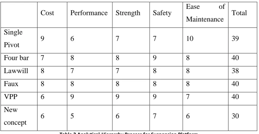
Table 2 Analytical-Hierarchy Process for Suspension Platform
From the above table, it can be seen that the best designs with regards to the criteria used are single pivot, four bar, Faux bar and also VPP. The next section will explain why the scores were given for each suspension platform and then look at further deciding factors in order to decide which type of suspension platform will be used.
Single Pivot
Single pivot scored well in the cost department due to the fact that less individual parts are used compared to other designs therefore less manufacturing cost and also the fact that it only has the one pivot point therefore requiring only one pair of bearings or bushes. Performance for this bike was rated lowest mainly due to the fact that without the use of a floating brake they tend to have a lot more brake jack then other designs. Also this design generally has more pedal bob than that of the other designs.
24 some control and lead to them having an accident and this is a similar case if the frame failed.
However ease of maintenance scored the highest for this design as there are only two bearings to replace and they are easily accessible without removing any other parts of the bike. Also the rear shock is easily accessible to be able to adjust it whenever and there is not any components that are hard to reach due to this design.
Four Bar
The four bar design was one of the highest scoring bikes due to many factors which will be discussed in this section. This design was rated lower in the cost department for a number of reasons including more individual parts and also if the Horst link is used, the usage to the patent must be purchased. The performance of this bike was also very high due to the fact that it reduces brake jack, has great small bump sensitivity and also doesn‟t suffer too badly from pedal bob.
The strength of this suspension platform was one of the highest due to the fact there has not been too many cases of this type of frame failing prematurely. Like the single pivot design the most common place for cracks to appear is around the headtube. However this type of failing at this region cannot be fully blamed on the suspension platform but the strength of the material as many of the bikes are very similar in design in this region with different companies having different ways of gusseting for strength. However this design has been known to fail within the suspension of the frame and therefore this reduced the score slightly. The next criterion that this design was rated for was that of safety and this design rated highly for this section due to many reasons. As stated earlier this suspension design reduces both brake jack and pedal bob which allows the user to be more in control of the bike and therefore increasing safety. Also the rate at which this type of design currently fails is fairly low so this also increases the score for this criterion.
25 the bearings can be hindered by other parts of the suspension design and also other components of the bicycle such as the chain guide.
Lawwill
The Lawwill design was one of the lowest scoring suspension platforms due to a number of reasons including a lower score in performance and strength. The cost for this type of suspension scored relatively high as the number of parts is slightly lower than a four bar design however there are more parts than on a single pivot frame. The performance was rated slightly lower than other frame designs as the way in which the suspension works is not as efficient as some of the other deigns. This is due to a number of reasons such as where the linkages are connected and also the wheel path that the rear wheel follows when the suspension is being used.
The strength for this suspension platform was rated slightly lower than that of the other variants of the four bar linkage as there is a more reports of this frame cracking than other suspension platforms. However, like many of the other frames, this cracking is located at the headtube but there have been cases when the crack has formed in the rear suspension. Once again this is more down to the material and will be looked at in a later chapter. The next area that his suspension platform was rated for was that of safety and this suspension platform rated highly as it doesn‟t have too many hassles with problems such as brake jack and pedal bob. Also there are normally clean frames without any pultrusion that can cause injury to the rider but once again this is more directly rated to the company that builds the frame.
The last criterion that this suspension platform was rated for was ease of maintenance and it scored relatively high as there normally isn‟t any hassles in reaching the bearings and access to the shock is hindered.
Faux
26 The strength of this frame was rated quite high as there have been a few cases of cracking within the parts assisting with the rear suspension but most failures are located at the head tube as is the case with other frames. This is again is due to the material used and whether or not sufficient gusted has been used to achieve the required strength. The next area this bike was assessed in was that of safety and as with the other four bar variants, it was awarded a fairly high score due to the fact that it doesn‟t suffer from too much brake jack and pedal bob. Next it was rated on the ease of maintenance and once again scored lower than the single pivot but not as low as some other designs. This is because the access to the bearings and rear shock is hindered more than that of a single pivot but it is still not overly hard to access.
VPP
This design was one of the higher scoring designs for many reasons but the two areas which really affected it were the cost and also the ease of maintenance which will be talked about shortly. This suspension platform scored fairly low in the cost department due to two reasons including the cost to use the patented designs and the also there are number of extra parts involved with this frame. The extra parts involved are machined to allow the pivot system which is used therefore increases the cost to a figure a lot higher than that of the other designs.
However the performance of this bike was rated very high as many people have stated that this is best suspension platform that they have used due to the fact that there is minimal brake jack and pedal bob. These are eliminated due the way in which the rear suspension works with the virtual pivot point. Due to these reasons this was the highest score bike with regards to performance. As with performance, this bike also scored the highest in the strength department as there have been minimal failures located around the rear suspension and most have been located around the headtube. The main reasons that this design has failed is that the rear swingarm does not have sufficient gusseted in certain areas so this is an easily solved problem.
27 correct rear shock then this is one the best performing and safest platform designs on the market. However there is a drawback with the performance and safety, which is the ease of maintenance which scored lower than other deigns due to how the rear suspension is assembled. There are a number of other components such as the cranks and chain guide which interfere with the access to the bearings. Also due to the way this frame built, it is hard to reach the rear shock properly to adjust it.
New Concept
This was the lowest scoring frame as there would be a lot of design work that would have to be completed to guarantee that the frame worked well with regards to performance. This frame scored the lowest in the cost department due to the unknown cost of materials and also the design and testing of the product. A totally new design needs some in field testing to make sure it works correctly and then needs to be redesigned if it doesn‟t perform correctly. With the time and monetary constraints pertaining to this project, this is not a viable option to choose.
The performance of this bike was also rated fairly low as stated before, there is lot of research and development goes into new designs and this is not financially viable nor will time allow for this option. Strength and safety were also rated low due to fact that these are not known with a new design until it is complete and as stated earlier, time will not allow this option. Ease of maintenance was rated low due to the same reasons.
Selected Design
28 too similar to other designs. Due to these reasons, the faux bar was the suspension platform that was decided to be used for its uniqueness and also the advantages of being fairly lightweight and reduced pedal kickback. While pedal bob and brake jack are the disadvantages, these are going to be reduced as much as possible.
3.2.2 Component Selection
Now that the type of suspension platform to be used has been decided upon, the final design work will be carried out and this section will look at each of the components chosen and why these were chosen and also look at the final design.
The first step in the design is to look at existing components which must be able to be attached to the frame without any modifications to these current products. These products were looked at in chapter 2.3.3 and briefly explained but this section will look at selection of each of components and why they have been selected. Two main components which allow the mountain bike to have the amount of suspension it does are the forks and the rear shock so these will be looked at first as these are some of the more major components.
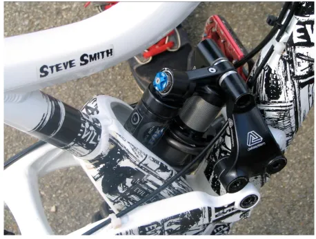
Forks
The forks are a major component for the design of a mountain bike to work properly and assist with handling and also rideability. There are currently two brands of forks which lead the way in this technology and both are very similar in geometry and how they mount to the frame. These two forks are Fox 40‟s and Rock Shox Boxxers and these are required to be able to select the correct geometry on the frame.
29 and the lightness of the 1-1/8” steerer tube called the E2 tapered. The size will be picked in chapter 3.2.3.
Rear shock
The rear shock however is more important than the forks as there are many sizes which will affect the geometry and amount of suspension that the frame has. As can be seen in chapter 2.3.3 there are many different size shocks which are currently available with majority of sizes being in the 8.75”-9.25” eye to eye and 2.75” – 3” stroke length region.
There are a number of frame characteristics that must be chosen now in order for the design to proceed. First the amount of suspension required is to be chosen in order to decide which size shock will be suited best. Tisue (n.d.) states that the optimal amount of rear suspension for a downhill mountain bike is around 7 to 10 inches. For previous experience, it is found that bike with smaller amounts of travel are best suited to less technical tracks and slightly easier to handle while a bike with larger amounts of travel generally is better over rougher terrain. However many longer travel bikes show the same rideability as smaller travel bikes. For this project I have decided to have a frame with about 8.5 -9 inches of travel as that is what I have found is best suited to the trails that are located in Australia.
30
Bottom Bracket
This component has an ISO standard so the only problem that is faced in deciding the shell width. According to Brown (2010), the standard ISO sizing for this component is 34.6-34.9mm outside diameter, 33.6-33.9mm inside diameter with a nominal thread of 1.37” x 24 TPI. There are a number of widths available with include 68mm, 73mm and 83mm with majority of downhill bikes having the 83mm so this will be the size that is used due to the fact that there are a number of components to fit this size.
Seat Post
Seat post is another component that has an unofficial standard for high-quality bikes. Brown (2009) states the standard size for seat posts is 24.2mm. Since this is being designed to be a high-quality bike, this will be the size seat tube that is used and the design will incorporate this size seat post.
Rear brake
The rear brake is another component which has standard sizes of 6, 7 and 8” in diameter. Majority of bikes are designed to be able to fit a 6” rotor with the brae bolted straight to the frame. However through the use of adaptors any frame should be able to use a 7 or 8” inch so once again there is standard size which most mountain bikes follow. As this is the case the rear brake mount will be designed to allow the use of a 6” rotor without any adaptors.
Rear Axle
The rear axle like many other components of the downhill mountain bike has two standard sizes which allow the rear wheel to be built around. The two standard sizes of rear axle are 135mm x 12mm and 150mm x 12mm. There is no evidence to support that one size is better so this component will not be selected yet. The frame will need to be able to fit the 12mm axle so this will be designed for with the width be selected later in the design process.
Derailleur
31 first is that it is made from a weaker aluminium alloy and is designed to break instead of the derailleur as it is a lot cheaper to replace. The average cost of a derailleur from Chain Reaction Cycles is $80-$180 while a hanger is generally around the $20-$30.
From the above reasons, it has been decided to use a hanger which will create a little bit more work to design this part to integrate with the frame. Hopefully, this option will work at cheaper in the long run for the end user as they will only need to buy a cheap hanger instead of an expensive derailleur.
3.2.3 Final Design
Now that the components that will be used have been selected, the actual design process can begin. Each part will be looked at in the order in which it was designed or decided upon in to provide a future guideline for the design of a downhill mountain bike.
Bottom Bracket Shell
There is one part on the frame that can be modelled straight away without too much design work as it has an ISO standard size. This is the bottom bracket shell, which as stated in chapter 3.2.2 will have a size of 83mm width with a 33.9mm and 34.9mm inside and outside diameter respectively.
Head Tube
The second component that does not require a great deal of design work is the head tube as there are standard sizes for this component. The three sizes as stated in chapter 3.2.2 are 1-1/8”, 1.5” and E2 tapered. Each of the different sizes have their own disadvantages with the 1-1/8” being lighter but weaker, 15.5” is stronger but heavier and the E2 tapered having the added strength of the 1.5” without the same amount of weight added. The 1.5” and E2 tapered both have the advantage that they can be used with a 1.5” steerer tube with the use of spacers to make the required diameter.
32 reduce the head tube diameter to 1-1/8”. The E2 tapered looks to be the best option due to the fact that it had the added strength and also not as heavy as the 1.5” option. The added strength and stiffness of this option will outweigh the extra weight which will be added from the extra material and the spacers that will be required on the bottom of the head tube.
33
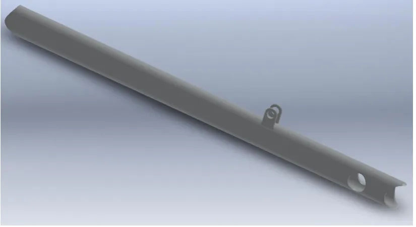
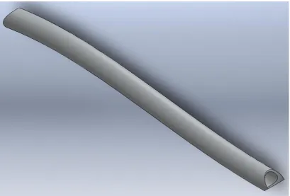
Down tube
The down tube is shown in figure 1 and is a very important part in the mountain bike frame. It is the main section that carries the load between the front of the bike to the rear and vice versa. The selection of this component is very crucial as a component which doesn‟t provide enough strength will break and if it is too thick it will add too much weight to the bike which will reduce the handling and rideability. This part of the frame must also be able to withstand impact from rocks, sticks and whatever else may flick up from the tyres.
There are a number of key factors that concern the design of this section of the frame including thickness, length and also the diameter. The length of this section is proportional to the wheelbase and head angle as there must be a certain amount of clearance for the rear wheel and the head angle also affects the wheelbase. As can be seen from table 1, head angle needs to be between 64 and 67o while the wheelbase must be somewhere between 1150 and 1210mm. Head angle must be within this range as a steeper or slacker head angle will result in a decrease in handling and a longer wheelbase will make the bike too hard to control in tighter corners and any shorter will cause the bike to lose stability in faster sections.
For this design, the rear wheel clearance is to be between 18-20mm to avoid the rear wheel seizing due to mud and other debris when used in a wet environment. With this measurement and measuring an existing tyre for the outside diameter which is 675mm it can be seen the minimum distance between the frame and centre of wheel is:
With the above measurement, and the requirement for the frame to have the mentioned head angel and wheelbase,
34 snuggly around the bottom bracket and head tube before being joined and therefore the diameter of this section cannot be too large or too small. As the diameter of the head tube and bottom bracket shell are 45mm and 34.9mm respectively, the length of the down tube can be found to be 649mm. This tube will also need to be machined in to order to connect with the bottom bracket and headtube which will need to circular shapes at the dimensions stated above.
There must also be a mount for the rear shock to connect to in order for the rear suspension to work effectively. As the rear shock size has been decided to be a 9.25” eye to eye x 2.75” stroke, the mounts will need to be a distance of around 200mm for the bottom bracket in order to achieve the correct leverage ratio. This dimension will need to be finalised at a later stage once the rest of the frame has been designed and slight modifications can be made in order to meet the requirements.
[image:44.595.113.526.508.733.2]This part will be made from butted tubing with an outside diameter of 45mm while the wall thickness will be 3mm at both ends and will reduce to a thickness of 2mm in the middle of the tube. Figure 13 shows the down tube while the detailed drawing is attached in appendix B. As can be seen from figure 13, the ends have been rounded off to allow a better contact area for the weld. This part will also have a bush welded into the located near the bottom bracket which will house the bearings and shaft for this pivot. This bush has been shown in the exploded view in appendix B.
35
Seat tube
The seat tube is used for a number of different reasons but the main two are to connect the down tube/bottom bracket to the top tube and also to allow the seat post to be inserted in order to be able to have a seat.
Due to the location of the shock, the seat tube will not be able to be of the conventional shape as shown in figure 1. As the shock is going where the seat tube would normally connect with the bottom bracket, an alternative seta tube configuration must be found. Figure 12 shows a design that has the rear shock in a similar location and how this problem can be solved. This is known as a split seat tube due to as can be seen in the figure below the tube is welded to a machined section which splits around the rear shock.
[image:45.595.108.567.370.716.2]
Figure 14 Split Seat Tube
36 The seat tube will be manufactured as two separate parts and then welded together in a similar way to the above figure. The top part of the seat tube will be hydroformed so to the unique shape that it has while the bottom part that separates out around the rear shock will be CNC machined.
The total length of this part needs to be roughly 465mm in order to achieve the required size for the frame. Due to the location of the shock, the bottom machined part will need to have a clearance of at least 220mm in order to avoid the rear shock being interfered by this part. The width between the two outer plates needs to be at least 50mm in order to allow the rear shock to fit while it also cannot be wider than 60mm as it will than protrude past the width of the bottom bracket. So from here it can be seen once the thicker machined part has been factor in the length of the hydroformed pipe needs to be 163mm.
37
Top tube
[image:47.595.230.399.88.570.2]The top tube provides extra stiffness for the frame and therefore is another very important part to the frame and also connects the top part of the seat tube to the headtube. Now that the rest of the parts that this section of the frame joins to have been designed this part is simple to design. There are only decisions that really need to be made such the diameter of the tube used, wall thickness and the manufacturing process. Once again this tube will be hydroformed due to the curve in this part. This
38 curve is just for cosmetic looks and does not serve a purpose other than that. Also the tubing will be the same concept as the butted tube with thicker ends and a thinner wall towards the middle where there isn‟t as much stress on the part.
[image:48.595.111.529.340.542.2]The length of this part needs to be roughly 480mm as can be seen in figure 16. Once again this part will have the machined ends in order to allow a better weld bead to be formed therefore increasing the strength of the frame. The outside diameter for this tube was decided to be 30mm as it doesn‟t need to be as strong and therefore to keep the weight to a minimum, this diameter was chosen. Also the wall thickness was decided to be 3mm at the ends and 2mm in the middle section of this part to keep consistent with the rest of the frame.
Figure 16 Top Tube Length
39 Figure 17 Top Tube
Chain stay
The chain stay for the type of design chosen will carry the majority of the load when the rear suspension is compressed. This is because this is the main bar that the suspension pivots on while the seat stay just alters the wheel path as the bike uses its suspension. This can be seen in figure 22 where it can easily been seen that the chain stay is the main link between the rear wheel and the front triangle.
40 The first step is to determine how long this part must be in order to achieve the rideability required. The length from the main pivot point to the required centre of the wheel is 435mm. The next step from here is to determine where the rear wheel will be passing this part in order to allow as much clearance as possible. Common tyre sizes for this type of mountain biking are between 2.3 and 2.5 inches so this gives an indication of how wide this section needs to be. The pedal clearance must also be kept in mind here so the width does not become too large and interfere with pedalling. Another factor that must be kept in mind is the fact that the rear axle must also be able to fit in the design so the rear of this part cannot be too wide. The rear axle size that has been decided upon is the 135mm x 12mm option. Also if the whole part is kept at a wider width, this would cause more stress on this section of the bike which would not be suitable therefore the best way to avoid this is to have a part that is bent to meet the requirements.
41 Figure 18 Wheel Clearance
[image:51.595.152.494.495.753.2]Figure 19 shows the full part while the detailed drawing is attached in appendix B.
42
Seat Stay
The seat stay as stated in the previous section is used to stiffen the rear triangle while also manipulating the travel into a friendly axle path in association with the linkage plate will be designed next. This part is also used in order to limit and modulate the amount of suspension that the frame has in order to achieve the required amount. If this part was not present, then the frame would have too much suspension and there would be too much force on the shock. This part also determines whether the rear suspension is either rising, falling or linear suspension which was discussed in 2.3.1.
[image:52.595.115.520.382.637.2]The axle path is very important for the rideability and handling of the bike. The most common axle path that is currently implemented by companies is the one shown in figure 20. There are other wheel paths used such as ones that only shorten or lengthen the wheel base however these are not as common as according to Young (2011) do not give the same rideability and handling.
Figure 20 Current Axle Path
43 The design for this part is relatively straight forward as it needs to mount towards the rear axle and also to the linkage plate which is designed in the next section. The length of this part was decided to be roughly 350mm however this may need to be slightly changed once other components have been designed and the suspension needs some slight tweaking. This part will also be required to have a few slight bends in order to allow the required
[image:53.595.117.519.340.657.2]Once the linkage plate had been designed there was a slight modification to make to the length of this part which there gave the required amount of suspension and wheel path. The final part is shown in figure 21 and the detailed drawing is attached in appendix B.
Figure 21 Seat stay
44
Linkage Plate
The linkage plays a major role in the design of this frame as this is the moving part that is attached to the rear shock and can be the deciding factor in whether the suspension will be effective or not.
As this linkage will be a more complex shape it will machined rather than other options to be able to achieve the required geometry. It will be started from a billet of material which will be specified in chapter 4.3 once the material selection has been completed and the initial dimensions of this billet will be specified within the next two paragraphs.
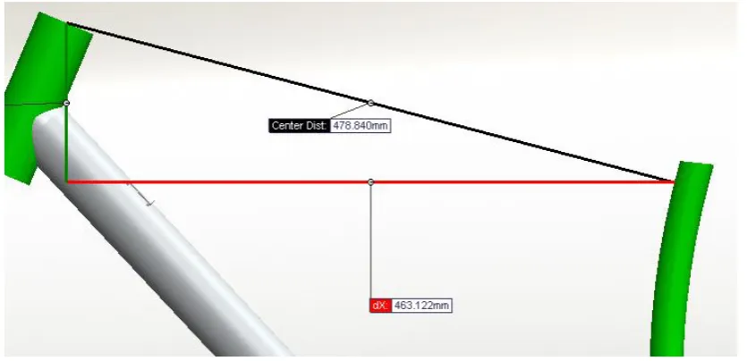
Now that all the other major structural parts have been designed and the geometry required has been decided this part will need to be designed in order to make the rest of bike conform to the required geometry. The required geometry with the shock fully extended and before the linkage plate is designed is shown in figure 22. The vertical distance which is shown by the green is at this height to achieve a bottom bracket height of 370mm which is slightly towards the higher end of the current designs but this was chosen as according to Moulten (2007), it will allow more ground clearance in rougher terrain and should be safer for the user in these parts of the track.
Figure 22 Required Geometry with no load on rear shock
45 wasted material. From figure 23, it can be seen that this part will need to take a complex shape to be able to fit around the seat tube without and interference and also to be able to be mounted in the correct positions. The next step in creating this part is to machine it in order for it to fit around existing parts of the frame. The first step is to cut the middle of the billet down to the dimensions shown in the detailed drawing in appendix B before cutting the ends in order to reduce unnecessary weight. From here the holes for where the pivots are going to be located need to be drilled to a size of 12mm in order to allow the shaft that the linkages will pivot on to be inserted and allow this to rotate freely.
46 Figure 24 Width of Linkage Plate