UNIVERSITI TEKNIKAL MALAYSIA MELAKA
IMPROVING MECHANICAL PROPERTIES OF FUSED
DEPOSITION MODELING PRINTED PART WITH
OPTIMIZED PARAMETER
This report is submitted in with the requirement of the Universiti Teknikal Malaysia Melaka (UTeM) for the Bachelor’s Degree in Manufacturing Engineering
Technology (Product Design) with Honours.
by
NOOR KHAIRUL NISA BINTI MOHD ALI B071410796
UNIVERSITI TEKNIKAL MALAYSIA
BORANG PENGESAHAN STATUS LAPORAN PROJEK SARJANA MUDA
TAJUK: Improving Mechanical Properties of Fused Deposition Modeling Printed Part with Optimized Parameter.
SESI PENGAJIAN: 2016/17 Semester 2
Saya NOOR KHAIRUL NISA BINTI MOHD ALI
mengaku membenarkan Laporan PSM ini disimpan di Perpustakaan Universiti Teknikal Malaysia Melaka (UTeM) dengan syarat-syarat kegunaan seperti berikut: 1. Laporan PSM adalah hak milik Universiti Teknikal Malaysia Melaka dan penulis. 2. Perpustakaan Universiti Teknikal Malaysia Melaka dibenarkan membuat salinan
untuk tujuan pengajian sahaja dengan izin penulis.
3. Perpustakaan dibenarkan membuat salinan laporan PSM ini sebagai bahan pertukaran antara institusi pengajian tinggi.
4. **Sila tandakan ( )
SULIT
TERHAD
TIDAK TERHAD
(Mengandungi maklumat yang berdarjah keselamatan atau kepentingan Malaysia sebagaimana yang termaktub dalam AKTA RAHSIA RASMI 1972)
(Mengandungi maklumat TERHAD yang telah ditentukan oleh organisasi/badan di mana penyelidikan dijalankan)
Alamat Tetap: No. 1 Lot 2406
Rumah Awam Sungai Sumun
Disahkanoleh:
DECLARATION
I hereby, declared this report entitled “Improving Mechanical Properties of Fused Deposition Modeling Printed Part with Optimized Parameter” is the results of my
own research except as cited in references.
Signature : ………..………
Author’s Name : NOOR KHAIRULNISA BINTI MOHD ALI
APPROVAL
This report is submitted to the Faculty of Engineering Technology of UTeM as a partial fulfillment of the requirements for the degree of the Bachelor’s Degree in Manufacturing Engineering Technology (Product Design) with Honours. The member of the supervisory is as follow:
………
(MADAM NURULAIN BINTI MAIDIN)
ABSTRAK
ABSTRACT
DEDICATION
To my beloved parents
MOHD ALI BIN PAGON AZIZAH BINTI SAED
Special dedicated to my supervisor
ACKNOWLEDGEMENT
TABLE OF CONTENT
Abstrak i
Abstract ii
Dedication iii
Acknowledgement iv
Table of Content v-vii
List of Tables viii
List of Figures ix-x
List Abbreviations, Symbols and Nomenclatures xi
CHAPTER 1 1
1.1 Background of the Project 1-2
1.2 Problem Statement 2
1.3 Objective 2
1.4 Scope of Study 3
CHAPTER 2 4
2.1 Rapid Prototyping Process 4
2.2 3D Printing 5
2.2.1 UP Plus 2 Machine 6-7
2.3 Fused Deposition Modeling 8-9
2.4 Optimized Parameter 9-10
2.4.1 Taguchi Method 10-11
2.5 Mechanical Properties 11
2.5.1 Tensile Strength Testing 12-14
2.5.2 Surface Roughness Testing 14- 15
CHAPTER 3 18
3.1 Project Planning 18
3.1.1 Gantt Chart 19-20
3.2 Research Methodology 21
3.2.1 Project Title 22
3.2.2 Gather the Information 22
3.2.3 Define the Dimension of Dog Bone 23
3.2.4 Material Selection 24
3.2.5 Study About of Method Used To Improvise the 25 Mechanical Properties
3.2.5.1 Taguchi Method 25-26
3.2.6 Parameter Setting 28
3.2.7 Taguchi Method Analysis 28-31
3.2.8 Design of Experiment (DOE) Analysis 32
3.2.9 Design Project 32-33
3.2.10 Fabrication of the Dog Bone 34-35
3.2.11 Analyze and Testing 35
3.2.11.1Testing Tensile Strength 35-36 3.2.11.2Testing Surface Roughness 37-38 3.2.12 Collect the Result and Data 39-41
CHAPTER 4 42
4.1 Result 42
4.2 Taguchi Method Analyses 45
4.2.1 Tensile Strength 45-48
4.2.2 Surface Roughness 49-51
4.3 Optimized Parameter Setting 52-53
CHAPTER 5 56
5.1 Conclusion 56-57
5.2 Recommendation 57
REFERENCES 58-59
LIST OF TABLES
2.1 Printer Physical Characteristics 7
2.2 Printer Specification 7
2.3 Printer Environment Specification 7
2.4 Parameter Setting 10
2.5 Example of Flat Test Specimen in Dimension and Tolerances per Standard ASTM E8
12
2.6 Example of Round Test Specimen in Dimension and Tolerances per Standard ASTM E8
13
3.1 Gantt Chart for Project Planning- PSM1 20
3.2 Dimension for Dog Bone 24
3.3 Design of Parameter and Levels 28
3.4 Signal to Noise Ratio Formula 29
3.5 Signal to Noise Ratio Formula in Table 30
3.6 Taguchi Method Arrangement 31
3.7 The Characteristic of the Mitutoyo SJ-410 38 3.8 Result and Data for Tensile Strength Testing 40 3.9 Result and Data for Surface Roughness Testing 41
4.1 Equation of Average 43
4.2 Design of Parameter and Levels in Minitab Software 43 4.3 Experiment Factor and Level Parameter 43
4.4 Result Tensile Strength 45
LIST OF FIGURES
2.1 Process of 3D Printing 5
2.2 UP Plus 2 Machines 6
2.3 Fused Deposition Modeling Printed Part 9 2.4 Formula of S/N Ratio ( small is better) 11
2.5 Universal Testing Machine 13
2.6 Standard Tensile Test Specimen 14
2.7 Example of Surface Roughness Graph 15
2.8 ABS Plastic Raw Material 16
2.9 Example of ABS Plastic Raw Material 17
3.1 3.2 3.3 3.4 3.5 3.6 3.7 3.8 3.9 3.10 3.11 3.12 3.13 3.14 3.15 3.16
Major Step in Methodology Flow Chart of Project – PSM1 Drawing the Part
Drawing for Dog Bone ASTM D638 Type IV Formula of S/N Ratio
Flow Chart of Project
Selected Taguchi Design in Orthogonal Array Design the Dog Bone in SolidWorks Software
Conversion the Part into Stereolithography (STL) file UP Plus 2 3D Printers Machine
Fabrication of the Dog Bone Universal Testing Machine (UTM) Specimen of Tensile Tests
Mitutoyo Model SJ- 410 Testing Surface Roughness
Typical Way to Obtain Surface Roughness
4.1 4.2 4.3 4.4
Main Effect Plot for Means(Tensile Strength) Main Effect Plot for S/N Ratios(Tensile Strength) Main Effect Plot for Mean(Surface Roughness) Main Effect Plot for S/N Ratios(Surface Roughness)
LIST OF ABBREVIATIONS, SYMBOLS, AND
NOMENCLATURE
FDM - Fused Deposition Modeling RP - Rapid Prototyping
CAD - Computer Aided Design 3D - Three Dimensional STL - Stereolithography File SLS - Selective Laser Sintering S/N - Signal to Noise
DOE - Design of Experiment UTM - Universal Testing Machine ASTM - Standard Test Methods BVI - Bulk Volume Irreducible BET - Brunauer–Emmett–Teller ABS - Acrylonitrile Butadiene Styrene Ra - Roughness Average
INTRODUCTION
CHAPTER 1
This chapter describes the background of the project and briefly explains the problem statement in this research and objectives of the study. This chapter also includes the scope of study for analysis the mechanical properties of fused deposition modeling (FDM). Besides that, this chapter will be also discussing for improving the mechanical properties of Fused Deposition Modeling (FDM).
1.1 Background of the Project
mechanical properties of Fused Deposition Modeling (FDM) such as the tensile strength and surface roughness. However, the result obtained for tensile strength and surface roughness are not a good result. So, need to find a suitable method to improve the mechanical properties in terms of tensile strength and surface roughness. Therefore, in Fused Deposition Modeling (FDM) are also have some type of 3d printer which is high end and an open-source. For this project, a machine used to produce the prototypes is 3d printer machine known as Up plus 2 which an open-source fused deposition modeling 3d printer. Besides that, it is small, reasonably priced 3D printer that offers an out-of-the-box printing solution.
1.2 Problem Statement
Nowadays, 3D printing via Fused Deposition Modeling (FDM) has developed to the probably most common rapid prototyping technology due to its ease of use and a broad range of available materials. However, the fluctuations of temperature during production will affect the mechanical properties such as tensile strength and surface roughness. Therefore, the main problem of this project is how to improve the mechanical properties of Fused Deposition Modeling (FDM) printed part by using the optimized parameter setting.
1.3 Objectives
The objective of this project is to improving mechanical properties of fused deposition modeling printed part with an optimized parameter. The objectives of these projects are:
1. To study and test mechanical properties (tensile strength and surface roughness) of the Fused Deposition Modeling (FDM) printed part. 2. To propose the best value for mechanical properties (tensile strength
1.4 Scope of Study
This chapter describes the material and process in this project. Then, explains about type of machine used in this project. Besides that, it also describes about mechanical properties of Fused Deposition Modeling (FDM) such as tensile strength and surface roughness from the previous journal and according the website. After that, the optimized parameter that used to improving the mechanical properties from the previous journal was also explained in this chapter.
2.1 Rapid Prototyping Process
Rapid Prototyping (RP) can be defined as a group of techniques used to quickly fabricate a fabricate prototype or assembly using three-dimensional Computer Aided Design (CAD) data. Rapid Prototyping is fast and low cost manufacturing a small series of component directly from the component geometry parameterization stored in a 3-dimensional CAD model Kotlinski (2014).
In addition to providing 3-D visualization for digitally rendered items, rapid prototyping can be used to test the efficiency of a part or product design before it is manufactured in larger quantities. Testing may have more to do with the shape or size of a design, rather than its strength or durability, because the prototype may not be made of the same material as the final product. Rapid Prototyping has also been referred to as solid free-form manufacturing; computer automated manufacturing, and layered manufacturing. In addition, Rapid Prototyping models can be used for
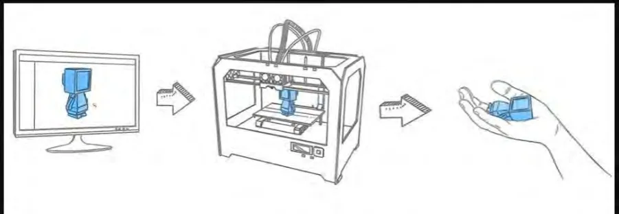
2.2 3D Printing
[image:20.595.115.566.356.512.2]3D printing is a processes and equipment used in the synthesis of a three-dimensional object. 3D printing is also known as additive manufacturing. Therefore, the numerous available 3D printing processes tend to be additive in nature with a few key differences. The main areas in which these processes differ are the technologies used in the process and the materials. Then, 3D printing signals the beginning of a third industrial revolution succeeding the production line assembly that dominated manufacturing starting in the late 19th century. Some methods use melting or softening material to produce the layers. Selective Laser Sintering (SLS) and Fused Deposition Modeling (FDM) are the most common technologies using this way of 3D printing.
Figure 2.1:Process of 3D Printing
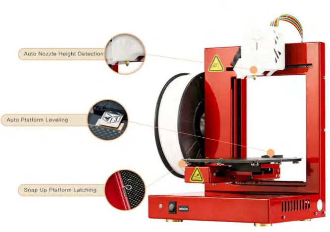
2.2.1 UP Plus 2 Machine
[image:21.595.172.506.356.590.2]The UP Plus 2 is an original standard bearer in great 3D printing at an affordable price, the UP Plus 2 has been employed for prototyping and final product creation in a wide array of industries including aerospace, medical, dental, science, architecture, industrial and mechanical engineering, scale model creation and more. Besides that, the UP Plus 2 have need groundbreaking and time-saving feature and was the first 3D printer in its class with an automatic platform calibration system. A probe’s sensor checks nine different points on the build surface for irregularities. Furthermore, the UP Plus 2 also have there is variation from one point to another and then has compensation settings is automatically entered into UP Studio. Not only does the Plus 2 automatically calibrate platform level, it also automatically calibrates nozzle height.
Figure 2.2:UP Plus 2 Machines
Table 2.1: Printer Physical Characteristics(‘UP Plus 2 3D Printer User Manual UP Plus 2 3D Printer User Manual’, 2013)
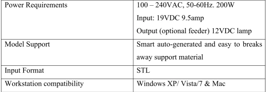
Table 2.2: Printer Specification(‘UP Plus 2 3D Printer User Manual UP Plus 2 3D Printer User Manual’, 2013)
Power Requirements 100 – 240VAC, 50-60Hz. 200W Input: 19VDC 9.5amp
Output (optional feeder) 12VDC lamp Model Support Smart auto-generated and easy to breaks
away support material
Input Format STL
Workstation compatibility Windows XP/ Vista/7 & Mac
Table 2.3: Printer Environment Specification(‘UP Plus 2 3D Printer User Manual UP Plus 2 3D Printer User Manual’, 2013)
Ambient temperature 15oC – 30oC
Relative humidity 20% - 50%
Printing Material ABS or PLA
Material Colour White
Layer Thickness 0.15mm-0.40mm
Print Speed (fine)10 – (fast) 100cm3/h
Print Bed Size 140mm x 140mm x 135mm
Printer Weight 5KG (11 1b)
Printer Size 245mm x 260mm x 350mm
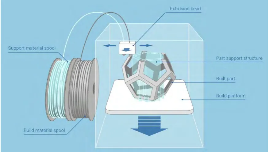
[image:22.595.106.531.382.529.2]2.3 Fused Deposition Modeling
Fused Deposition Modeling (FDM) is an additive manufacturing technology commonly used for modeling, prototyping, and production applications. It is one of the techniques used for 3D printing. The technology was developed by S. Scott Crump in the late 1980s and was commercialized in 1990 (Rayegani and Onwubolu, 2014). FDM begins with a software process which processes an STL file (Stereolithography file format), mathematically slicing and orienting the model for the build process. If required, support structures may be generated. The machine may dispense multiple materials to achieve different goals: For example, one may use one material to build up the model and use another as a soluble support structure or one could use multiple colors of the same type of thermoplastic on the same model.
Figure 2.3: Fused Deposition Modeling Printed Part
(Source: < https://www.additively.com/en/learn-about/fused-deposition-modeling> 20 APRIL 2017)
2.4 Optimized Parameter