SINTEF, Trondheim, Norway 17-19 June 2014
CFD 2014
1
MULTI-SCALE PROCESS MODELS TO ENABLE THE EMBEDDING OF CFD
DERIVED FUNCTIONS: CURTAIN DRAG IN FLIGHTED ROTARY DRYERS
Andrew LEE2, Madoc SHEEHAN1 , Phil SCHNEIDER1 1
James Cook University, 4812 Townsville, AUSTRALIA 2
University of Melbourne, 3010 Melbourne, AUSTRALIA
Email: [email protected]
ABSTRACT
Flighted rotary dryers are large industrial devices which are commonly used to dry mineral ores and mineral concentrates, as well as other valuable commodity products. They are high capital cost units as well as large consumers of energy. Solids movement and energy exchanges within these devices occurs via a range of complex mechanisms that involve rolling and bouncing in a dense bed of solids, as well as the falling through a cross-flowing gas stream in lean particle curtains. Although a fundamental approach is attractive, full CFD simulations of such devices would be prohibitively expensive. The complexity of such a model would preclude its use for design and control applications, which are the most prevalent concerns to industry. Pseudo-physical compartment modelling is a powerful alternative technique that can be used to reproduce, in a physically meaningful way, the important characteristics of dryers such as residence time distributions and loading states. This scalable modelling approach also provides a convenient multi-scale structure that facilitates the representation of a system (in this case a flighted rotary dryer) as a series of smaller, distinctive, interacting phases. It is these smaller phase structures, such as the air-borne phase, that are suitable for modelling with either CFD or DEM type approaches. In this paper CFD modelling of single particle curtains and multiple side-by-side particle curtains is presented, with particular emphasis on quantifying gas induced drag and gas penetration into the curtain phase. The results are discussed in terms of their suitability to integrate CFD derived phase information within the broad process model. The simulations described in this paper provide valuable insights into the dryer design considerations such as flight serrations and axial flight staggering. The methodology presented in this paper provides an example that could be adapted to enable the evaporation, convection and radiation heat transfer in curtains to be accounted for.
Keywords: CFD, compartment model, particle curtain, drag, multi-scale, dryers
INTRODUCTION
Flighted rotary dryers (FRD's) are used extensively in a range of industries for control of the temperature and moisture content of free flowing, particulate solids, such as grains, sugar, and mineral ores as shown in Fig.1. FRDs range from small bench scale apparatus in pharmaceutical manufacturing, to 30m long, 6m diameter, industrial ore dryers. FRDs offer simplicity, low operating costs, and handle a wide range of throughputs and feed-stocks. Due to their size, rotary dryers often represent a significant capital expense. Thus it is necessary to have a good understanding of dryer operations and design features to ensure that the unit meets desired operational requirements.
2
falling particles, causing dispersion of the solids within the dryer. The rolling solids also interact with the drying gasses, but to a lesser extent.Whilst flighted rotary dryers are widely used and have been widely studied, their complex solids transport behaviour and the difficulty in integrating solids transport and heat and mass transfer phenomena have proved to be significant stumbling blocks. As a rotary dryer and the behaviour of its contents are three-dimensional, a comprehensive model of a dryer would need to be three-dimensional in order to capture the full detail of the solids transport. Furthermore, both granular flow (flight and kilning solids) and pneumatic flow (curtaining solids) occur within these devices and particle numbers in a full scale unit are enormous. Clearly, a rigorous fluid dynamic or discrete element model of the entire dryer is not feasible. Unfortunately, simple empirical models have been shown to be unable to predict the full behaviour of the system (Cao and Langrish (1999), Lee et al. (2009)).
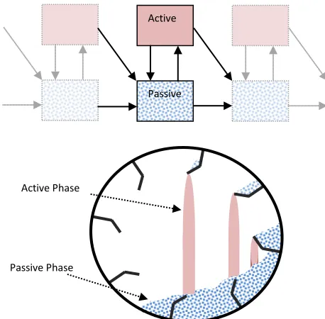
Figure 1. Cross section of an operating flighted rotary dryer (below) and the corresponding pseudo-physical compartment model (above). The light-shaded solids are the airborne solids (curtains) and the patterned solids are the flight and drum borne solids.
Early semi-empirical applications of compartment modelling of FRD's by both Matchett and Baker (1987) and Duchesne et al (1996) led to the development of more realistic representations of dryers. The model structures were capable of reproducing typical dryer experimental observations such as residence time distributions. The important model features developed in these works were the use of a twin tanks in series model structure, where one tank represented the flight and drum borne solids and
the other tank represented the airborne solids (see Figure 1). Sheehan et al. (2005) and Britton et al. (2006) extended this work by developing a multi-scale flighted rotary dryer model, integrating physically-derived model parameters into the compartment model structure, in an approach they called pseudo-physical compartment modelling (PPCM). In this approach, scalable dynamic models were derived and the effects of internal geometry, operating conditions and solids flow properties on dryer performance could be accurately predicted. Each well-mixed tank was defined by its corresponding dynamic mass and energy conservation equations, as well as geometric capacity constraints. A separate unloading flight geometry model was used to generate model parameters controlling the flows in and out of each tank or phase. The PPCM is an adaptable model framework, and it has been successfully used to model a full-scale zinc concentrate dryer with both flighted and unflighted sections (Ajayi, 2011) and a fluidised drum granulator (Rojas et al., 2010).
In the discussion that follows, we describe aspects of the process model in sufficient detail as to make obvious the potential to utilise CFD simulation to generate model parameters within the PPCM. In particular, we emphasise model parameters (such as the airborne solids residence time) that are responsible for moderating the flow and quantity of solids that enter the airborne phase.
The movement of solids between different phases is primarily due to the action of the flights lifting and discharging solids within the dryer. Cascading solids will be transported axially to the neighbouring dryer elements (i.e. tank) due to dryer inclination as well as gas-drag. Solids also roll or kiln along the drum base due to dryer inclination. Lee and Sheehan (2010) showed that for a free flowing material which discharges continuously from the flights, the discharging behaviour of a flight as it travels around the circumference of the dryer can be calculated solely from the geometry of the flight and drum, the amount of solids present in the flight, and the solids dynamic angle of repose. Thus, an unloading profile of the flight (mass flow versus time) can be calculated.
In previous examples of the PPCM, the geometric unloading profile was linked to a single particle model (SPM), which is used as an approximation for bulk curtain behaviour. Using the trajectory of an average particle, Newtons equations of motion are solved to obtain average properties that are then used to approximate the curtain behaviour. In particular, approximate air-borne and flight-borne residence times are used directly as the inter-phase transport
Active
Passive
Active Phase
[image:2.612.73.302.320.545.2]3
coefficients. For example, the solids flow rates out of each compartment in the model are calculated using the formF
i=
m t
i i whereF
i is the flow rate ofsolids leaving compartment
i
andm
i andt
i are thesolids holdup and residence time in compartment
i
, respectively. We propose that CFD simulation of particle curtains could be used instead of the SPM to determine more realistic values fort
i . Additionally, the SPM is used to calculate the axial advance for the average particle experiencing drag from cross flowing gas. Which is used within the PPCM to constrain tank lengths and to apportion flows to the surrounding tanks (Britton et al., 2006). CFD could be utilised in this context as well. Referring back to the broad PPCM framework, because smaller distinctive zones are defined within the larger unit model, it facilitates the integration of more sophisticated modelling (using CFD or DEM for example) of the individual phases.In this paper we use the case study of a flighted rotary dryer as context for describing new CFD modelling of drag within particle curtains. We describe the CFD modelling of a single cascading curtain as well as multiple cascading curtains and also discuss the potential for embedding CFD derived information within multi-scale process compartment models.
CFD curtain modelling
A number of researchers have studied the effects of the gas-solids interactions in the active phase on the solids transport operations within a rotary dryer. Obviously, the moving stream of drying gasses will result in a displacement of the falling solids due to drag effects. Previous research has demonstrated that the gas-solids interactions within a rotary dryer are complicated. Simplifications of the system, such as the extremes of assuming isolated spherical particles (maximum drag) or flat-plate behaviour (minimum drag) (Baker, 1992), are generally insufficient. However, modelling the gas-solids interactions within a single curtain of falling solids is well within the capabilities of current CFD packages.
In order to model the gas-solids interactions influencing the active phase, a multi-phase CFD approach was implemented in Ansys CFX® 5.7.1. Due to the large number of solid particles present a Lagrangian method was not feasible, whilst the solid curtain was not considered dense enough to warrant the use of a granular model for the solids. Thus an Eulerian-Eulerian approach was used with a full buoyancy model and a k-ε model for turbulence. Although the k-ε model remains the industry standard, and has been widely used to model
gas-solid systems (Du et al. (2006) for example), it's accuracy has been noted to depend on the use of sufficiently fine mesh and time step (Fletcher et al. (2006)). Uncertainty in the choice of turbulence modelling emphasizes the importance of experimental data to validate model predictions. In this work we draw confidence in our model choices and the resulting simulation results, from prior studies comparing experimental (isothermal) curtain profiles to the simulated curtain profiles that were determined using the same model approach, but for a scaled-down system. In those wind tunnel studies (Wardjiman et al. (2008, 2009)), both free falling curtains in still air and free falling curtains exposed to cross flowing gas were examined. Good agreement between the experimental and simulated results was obtained under both scenarios. Wardjiman et al. (2008, 2009) found that a cutoff solids volume fraction of 5.6x10⁻⁴ corresponded well with the experimentally observed curtain boundaries, and a similar threshold of 4.3x10⁻⁴ has been used in this work.However, to ensure complete confidence in the results presented in this paper, a comprehensive set of experimental data for curtain profiles would be required.
Gas-solids interactions occurring within a full rotary dryer are complex, with multiple flights unloading solids at different locations. Each of these individual curtains will have different mass flow rates, particle velocities and solids volume fractions, and the presence of the curtains will affect the flow of gas through the dryer. In this work, two series of simulations were conducted. The first studied a single curtain of solids falling perpendicular to a moving gas stream (i.e. a single curtain in isolation) and the second examined multiple parallel curtains to determine whether the presence of multiple curtains affected the displacement of solids and extent of gas penetration.
Single Curtain Studies
4
zone for the gas stream. Turbulence was modelled using the k-ε model and a full buoyancy model was used. Drag forces were modelled using the Schiller-Naumann (Schiller and Schiller-Naumann, 1935) equation assuming a particle size of 850 µm.The numerical domain was discretised with a 9 mm tetrahedral mesh applied to the region occupied by the particle curtain and extended for a minimum of 50 mm beyond the expected curtain boundaries. The remainder of the tunnel was discretised using a maximum mesh size of 35mm, resulting in a total mesh of 136,000 nodes. The system was solved using the inbuilt Automatic Timescale calculator in CFX 5.7.1 (Ansys CFX (2006)) until all residuals were less than 10-4, or 100 iterations had been performed. The gas velocity at the inlet to the duct was specified at the experimental conditions and at the solids inlet, the mass flow rate, velocity and initial solids volume fraction were specified. The inlet solids volume fraction of solids,
r
p0 , was calculated based onexperimental data using the following equation
0
0
p p
p
M
r
U A
ρ
=
, whereM
p is the mass flow rate ofsolids entering the system, U0 is the initial velocity of
the solids entering the duct, and
A
is the cross-sectional area of the solids inlet. At the downstream end of the duct, the boundary was defined as an outlet boundary, such that material can only exit the systemthrough this boundary. In the absence of experimental data, the gas and solids inlets were given a turbulence intensity of 5% (Ansys CFX (2006)). The remaining boundary conditions were governed by the no-slip condition.
In order to test the influence of gas velocity on the curtain displacement, simulations were conducted with a curtain length of 0.5m, and gas velocities of 0.5 m/s (slow), 1 m/s (normal gas velocity for rotary dryers) and 2 m/s (fast). Although not presented here, simulations were also conducted with 5 different curtain lengths (i.e. axial distances) to study how far the moving gas stream penetrated the falling curtain, and how solids displacement varied with curtain length.
[image:4.612.143.477.423.639.2]Figure shows the simulated results for the curtain profile measured at the centreline of the tunnel, for a 0.5 m long curtain at different gas velocities. It can be clearly seen that the gas velocity has a significant effect on the leading edge of the curtain, with increasing gas velocities causing greater displacement of the solids. At the trailing edge however, the profile is very similar at both 0.5 m/s and 1 m/s, with the solids falling almost vertically under these conditions. It is only with a gas velocity of 2 m/s that the gas is able to fully penetrate and the trailing edge of the curtain is displaced.
Figure 2. Solids curtain profile at different gas velocities (0.5 - 2m/s).
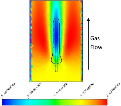
Figure shows a colour map of the horizontal component of the gas velocity for the 1 m/s simulation. These measurements were taken in the
horizontal plane at a height of 1 m above the tunnel floor (arbitrarily chosen to illustrate the behaviour of the system), with the gas being introduced from the
Leading Edge
5
bottom of the figure. The black line indicates the edge of the particle curtain (defined as a solids volume fraction of 0.43×10⁻³). Figure clearly shows the gas being channelled around the solids curtain, with increases of up to 25% in the gas velocity being observed around the curtain. It can also be seen that the moving gas only penetrates a short distance into the solid curtain, producing an area of negligible horizontal velocity throughout large portions of the curtain. Figure shows the same measurement as Figure for an initial gas velocity of 2 m/s, and again gas velocities up to 25% greater than the initial velocity can be observed. Clearly, the increased gas velocity has a significant impact on the leading edge of the curtain, causing appreciable curtain displacement and compression. It can also be seen that the moving gas penetrates deeper into the curtain than in the 1 m/s simulation, however there is still an area of negligible horizontal gas velocity throughout large portions of the curtain. Given that flights are often staggered to maximise gas-solid interactions, these results provide useful guides to appropriate spacing. In industry flights are typically staggered at around 1-2 m intervals, yet this study suggests that staggering of between 10 and 20 cm would be more effective in promoting gas penetration.Figure 3. Horizontal gas velocity colour map at 1 m above tunnel floor (1 m/s initial gas velocity, 0.5 m inlet, 5.18 kg/m.s solids flow rate). Units are m/s.
Figure 4. Horizontal gas velocity colour map at 1 m above tunnel floor (2 m/s initial gas velocity, 0.5 m inlet, 5.18 kg/m.s solids flow rate). Units are m/s.
From the results of these simulations, it is possible to assess curtain displacement resulting from changes in gas velocity. Figure shows the trend in the displacement of the curtains leading edge over a fall of 2 metres at the gas velocities studied. The curtain displacement is well represented by a second order polynomial, which reconciles with fact that drag is proportional to velocity squared.
Simulations such as this provide an example whereby CFD can be used to generate correlations to use in up-scaled process models such as an industrial FRD, modelled using the PPCM framework. In this case, PPCM parameters (e.g. curtain displacement) could be derived as functions of operating variables such as gas velocity. Extensions would include the effects of variations in solids flow rates and particle size into these CFD derived correlations. Furthermore, using averaged CFD curtain properties such as the fall time (i.e. mean residence times in the active phase), can be used to replace SPM predictions. This would be advantageous because it is well known that drag in curtains is different to that experienced by isolated single particles (Hurby et al. (1988)).
The predicted displacement of the solids due to gas-solids interactions appears small in comparison to those reported by Baker (1992), which is likely due to and different initial conditions of the curtain. In these simulations, the initial conditions were taken using experimental data from a flight unloading apparatus with an un-serrated flight (Lee and Sheehan, 2010). However, most industrial dryer use serrated flights, which create a broader, less dense curtain. This reduced density allows greater gas-solids interaction and thus greater displacement of solids. Another possible factor affecting the results is the interactions between curtains. In a system with
Gas
Flow
[image:5.612.75.286.366.555.2]6
multiple curtains there will not be as much space available for channelling around the curtains, which [image:6.612.134.481.88.300.2]may cause greater interactions between the gas and solids.
Figure 5. Simulated single curtain displacement over 2 metres at different gas velocities.
Multiple Curtain Studies
The phenomenon of channelling of the gas flow around the falling curtains in a rotary dryer was first considered by Baker (1992) as part of his studies into the gas-solids interactions. In a system with multiple curtains, the gas flow should channel between curtains, resulting in channels of high gas velocity that may influence solid particles at the curtain edges. In order to understand channelling behaviour, a series of simulations were conducted using multiple curtains with different spacing between curtains.
CFD simulations were conducted using the average particle curtain properties used for the single curtain simulations for all curtains, which is a reasonable approximation for the middle of the unloading profile where the unloading rate is reasonably constant. The simulations were conducted using a tunnel 500 mm high, 340 mm across and 800 mm long. A smaller system geometry (compared to the single curtain simulations) was used due to the greater mesh requirements to resolve the gas-solids interactions for the multiple curtains. Solids were introduced along the top of the tunnel starting 100 mm from the gas inlet, and allowing 200 mm between the end of the inlet and the end of the tunnel. The tunnel was discretised with an 8.4 mm tetrahedral mesh across the entire tunnel, resulting in 368,780 nodes. Four simulations were run with curtain spacing varying between 50 mm and 80mm. Curtains were equally spaced across the tunnel, with the two outermost curtains extended to reach the wall to prevent gas for being channelled along the wall without affecting the curtain. Due to the fixed size of the tunnel, the
constant curtain spacing meant that the number of curtains present in the simulations also varied with curtain spacing, making extrapolations based on total curtain numbers difficult.
7
Figure 6. Solids volume fraction colour map at 0.25 mabove tunnel floor with 50 mm curtain spacing.
Figure 7. Solids volume fraction colour map at 0.25 m above tunnel floor with 80 mm curtain spacing.
[image:7.612.328.538.58.183.2]This means that at low curtain spacing, where the curtains have merged into a single uniform phase, the gas flow through the curtain should also be uniform, as there are no regions of reduced solids volume fraction through which the gas will channel. As the curtain spacing increases, and individual curtains become distinct, and the regions of lower solids volume fraction between the curtains will allow for the gas to be channelled. This effect is seen in Figures 8 and 9, which show the gas velocity profile through the same cross-section of the tunnel. The thick black line indicates the contour of a solids volume fraction of 4.3x10⁻³.
[image:7.612.74.288.216.343.2]Figure 8. Horizontal gas velocity colour map at 0.25 m above tunnel floor with 50 mm curtain spacing. Units are m/s and the inlet gas velocity is 1m/s.
Figure 9. Horizontal gas velocity colour map at 0.25 m above tunnel floor with 80 mm curtain spacing.
Units are m/s and the inlet gas velocity is 1m/s.
[image:7.612.76.287.539.664.2]8
Figure 10. Curtain profiles for different curtain spacing and cross flowing gas at 1m/s.
It can be clearly seen that the single curtain simulation predicts less displacement of the solids curtain, due to the channelling of the gas around the curtain. It can be seen that the effects of the gas-solids interactions occur primarily at the leading edge of the curtain, with a significant displacement of solids being observed.
CONCLUSIONS
The pseudo-physical compartment model is presented as a convenient structure to reduce the size and scale of modelled phenomena whist maintaining physical realism. In this case, a flighted rotary dryer is modelled in such a way that the behaviour of falling curtains of particles is isolated and emphasised. Eularian-Eularian CFD simulations of gas induced drag on the curtain phase within a flighted rotary dryer are described. Both single curtain simulations and multiple curtain simulations are presented. Examples illustrating the use of CFD results to develop correlations suitable for use within the PPCM are described.
Single curtain simulations show substantial channelling of gas around the sides of the particle curtain, leading to reduced particle drag (except at the leading edge) and low levels of gas penetration (20cm or less at 2m/s gas velocity). However, simulation of multiple curtains lead to more significant gas penetration that is dependent on the curtain to curtain spacing distances. In terms of particle drag, the displacements of solids in the single curtain simulations with 850 µm particles are less than expected. The simulations conducted in this
study used data measured from unserrated flights, resulting in thinner, denser curtains, that potentially under-predict solids displacement that would be observed when using serrated flights. An experimental study of the unloading behaviour of serrated flights is necessary in order to develop a better model for the gas-solids interactions in flighted rotary dryers.
REFERENCES
Ajayi OO (2011) Multiscale modelling of industrial flighted rotary dryers. PhD thesis, School of
Engineering and Physical Sciences, James Cook University, Townsville.
Ansys CFX Solver Modelling Guide, (2006), Ansys Inc., Canonsburg
Baker, C.G.J., (1992), “Air-Solids Drag in Cascading Rotary Dryers”, Drying Technology, 10, 365-393
Britton P.F., Sheehan M.E. and Schneider P.A., (2006) A physical description of solids transport in flighted rotary dryers. Powder Technology 165, 153-160.
Cao, W.F. and Langrish, T.A.G., (1999)
Comparison of residence time models for cascading rotary dryers. Drying Technology, 17 (4&5), 825-836.
Du, W., Bao, X., Xu, J. and Wei, W., (2006) “Computational fluid dynamics modelling of spouted bed: assessment of drag coefficient correlations”, Chem. Eng. Science, 61, 1401-1420 Duchesne, C., Thibault, J. and Bazin, C., (1996) “Modelling of the Solids Transportation within an
Leading Edge
9
Industrial Rotary Dryer: A Simple Model”, Ind. Eng. Chem. Research, 35, 2334-2341Fletcher, D.F., Guo, B., Harvie, D., Langrish, T.A.G., Nijdam, J.J. and Williams, J., (2006) “What is important in the simulation of spray dryer performance and how do current CFD models perform? ”, App. Math. Modelling, 30, 1281-1292 Hurby, J., Steeper, R. Evans, G. and Crowe, C., (1988) An experimental and numerical study of flow and convective heat transfer in freely falling curtain of particles. Journal of Fluid Engineering - Trans ASME, 110, 172-181.
Lee A (2009) Modelling the solids transport phenomena within flighted rotary dryers. PhD thesis, School of Engineering and Physical Sciences, James Cook University, Townsville.
Lee, A. and Sheehan, M.E., (2010), “Development of a Geometric Flight Unloading Model for Flighted Rotary Dryers”, Powder Technology, 198, 395-403 Matchett, A.J. and Baker, C.G.J. (1987) Particle residence times in cascading rotary dryers Part 1 - Derivation of the two-stream model. Journal of Separation Process Technology, 8, 11-17. Rojas, R., Piña, J., Bucala, V., (2010), "Solids transport modeling in a fluidised drum granulator", Ind. Eng. Chem. Res., 49, 6986-6997
Schiller, L. and Naumann, Z., (1935), “A Drag Coefficient Correlation”, Zeitschrift des Vereines Deutscher Ingenieure, 77, 318-320
Sheehan, M.E., Britton, P. and Schneider, P.A., (2005), “A Model for Solids Transport in Flighted Rotary Dryers Based on Physical Considerations”, Chem. Eng. Science, 60, 4171-4182
Wardjiman, C., Lee, A., Sheehan, M. and Rhodes, M., (2008), “Behaviour of a Curtain of Particles Falling Through a Horizontal Gas Stream”, Powder Technology, 188(2), 110-118