lateral load cases
.
White Rose Research Online URL for this paper:
http://eprints.whiterose.ac.uk/145413/
Version: Published Version
Article:
Lu, H., Gilbert, M. orcid.org/0000-0003-4633-2839 and Tyas, A. (2019) Layout optimization
of building frames subject to gravity and lateral load cases. Structural and Multidisciplinary
Optimization. ISSN 1615-147X
https://doi.org/10.1007/s00158-019-02283-x
[email protected] https://eprints.whiterose.ac.uk/
Reuse
This article is distributed under the terms of the Creative Commons Attribution (CC BY) licence. This licence allows you to distribute, remix, tweak, and build upon the work, even commercially, as long as you credit the authors for the original work. More information and the full terms of the licence here:
https://creativecommons.org/licenses/
Takedown
If you consider content in White Rose Research Online to be in breach of UK law, please notify us by
Structural and Multidisciplinary Optimization https://doi.org/10.1007/s00158-019-02283-x
RESEARCH PAPER
Layout optimization of building frames subject to gravity
and lateral load cases
Hongjia Lu1
·Matthew Gilbert1 ·Andrew Tyas1
Received: 19 December 2018 / Revised: 16 March 2019 / Accepted: 11 April 2019
©The Author(s) 2019
Abstract
In this study, the optimal layout of the principal structural members forming a building frame are sought, considering both gravity and lateral loads. The plastic design layout optimization formulation is used, considering the multiple load cases arising from the requirements of a well-known structural design code. The superposition approach is shown to be applicable to the three primary load case problems involved. It is found that the optimal layouts identified differ from those obtained when bracing is sought for a pre-existing frame, already designed to resist gravity loads. A significant finding is that a parameter related to the difference in vertical and lateral loads to be applied in the applicable load cases is a key factor determining the optimal layout of frame members. Since applicable load cases are design code dependent, this also indicates that optimal layout will be strongly influenced by choice of design code. Simple benchmark problems and a practical building design example are used to illustrate the concepts explored.
Keywords Layout optimization·Topology optimization·Building frames·Multiple load cases
1 Introduction
Ensuring adequate resistance to lateral loads is central to the design of any building. When designing a building, structural engineers normally rely on codes of practice, which generally require that several separate load cases are considered. Often the load case which involves application of the maximum lateral load includes design gravity loads which are not at their maximum value. This is because it is considered improbable that maximum gravity loads will coincide with, say, maximum wind loads. As a result, in many bracing optimization studies, it is first assumed that the sizes of the main columns and beams in a structural frame are determined by consideration of gravity load cases (only), and that these members will have sufficient strength to play their required roles in resisting lateral loads without needing to be resized; this scenario has been considered by various workers (e.g. Kim et al.1998; Liang et al. 2000;
Responsible Editor: YoonYoung Kim
Matthew Gilbert [email protected]
1 Department of Civil and Structural Engineering, University of
Sheffield, Mappin Street, Sheffield, S1 3JD, UK
Ter´an-Gilmore and Coeto2011; Stromberg et al.2012), and was recently considered in more detail by Lu et al. (2018). There are in contrast relatively few examples of what may be termed ‘holistic’ optimization of the structural frame, in which all load cases are considered when identifying the locations and sizes of members forming the frame of a building. This runs contrary to recent practice in the field of structural engineering, where, for example, diagrid exoskeleton frames are increasingly being used to resist both vertical and lateral loads.
design the external form to resist gravity and wind loading. Instead of using prescribed joint positions, the external form was defined by a small number of parameters, enabling a complex geometric model to be manipulated rapidly (Foster and Partners2005). For the design of the visually striking CCTV headquarters building in Beijing, an iterative optimization process was used in the design of the bracing, adding or removing diagonals to meet the strength and stiffness requirements associated with a Level 1 earthquake (Carroll et al.2008).
Whilst these studies have yielded interesting findings, it appears that no rigorous academic studies of the holistic frame layout design problem have been conducted to date, in which the locations and sizes of principal members forming a building frame are sought. Addressing this is the main driver for the present study. Both theoretical and numerical layout optimization approaches are used to identify optimal framing systems capable of withstanding gravity loads only and also combined gravity plus lateral loading scenarios.
The paper is organized as follows: Section2describes the design optimization problem that will be considered and identifies a key parameter related to the load cases which turns out to greatly influence the layouts of the optimal building frames identified; Section3describes application of the techniques described to single and multi-storey building design examples; Section4describes application to the design of a small office building; finally, conclusions from the study are drawn in Section5.
2 Holistic design optimization problem
2.1 Layout optimization
The optimal layouts of discrete members in a framework can be identified using the layout optimization procedure, originally described by Dorn et al. (1964). In this procedure, nodes are laid out in a grid across the design domain, with all possible interconnections between nodes forming a ‘ground structure’. The basic single load case ‘plastic’ layout optimization formulation for a two-dimensional truss problem can be stated as follows:
min V =qTc
subject to Bq=f
qi+, qi−≥0, i=1,..., m
(1)
where there are m members and n nodes in the problem, and where V represents the volume of the structure, qT = {q1+, q1−, q2+, q2−,..., qm+, qm−},
cT = {l1/σ1+, l1/σ1−, l2/σ2+, l2/σ2−,..., lm/σm+, lm/σm−},
where and li, qi+, q
−
i , σ
+
i , σ
−
i represent, respectively, the
length, tensile member force, compressive member force, tensile stress capacity and compressive stress capacity
of member i. B is a 2n × 2m equilibrium matrix and
f = f1x, f1y, f2x, f2y,..., fnx, fyn, wherefjx andfjy rep-resent the component of load applied to node j in the x
and y directions respectively. This problem is in a form suitable for solution using linear programming (LP); the adaptive ‘member adding’ solution procedure proposed by Gilbert and Tyas (2003) can be used to reduce the cost of the computations involved.
2.2 Practical design considerations
Although it is common when designing a building frame manually to first design members to resist gravity loads (i.e. the constituent beams and columns), and to then design bracing elements, this may not lead to the best design. For example, it is possible that in the case of a tall, slender, frame that the design of the columns may be partly determined by the loads induced in them by the lateral load. Additionally, decoupling the different load cases in this way may mean that more optimal ‘holistic’ designs are missed. Therefore in this paper, all principal load cases are considered in the optimization.
As stated by Lu et al. (2018), for the design of steel framed buildings, British Standard 5950-1:2000 suggests the following load combinations:
p1:1.4Gk+1.6Qk (2a)
p2:1.0Gk+1.2Qk+1.2Wk (2b)
p3:1.0Gk+1.2Qk−1.2Wk (2c)
where Gk is the characteristic permanent load, Qk is the
characteristic imposed load and Wk is the characteristic
wind load. (For sake of simplicity notional horizontal forces are neglected.)
To tackle the resulting design problem, three assumptions were introduced by Lu et al. (2018):
– Assumption 1: The loads generated in the columns in load case (2b) and (2c) are always less than those resulting from load case (2a).
– Assumption 2: Vertical gravity loads are only carried by the columns in all load cases.
– Assumption 3: The sizes of pre-existing horizontal members (i.e. floor beams and/or slabs) are dominated by the gravity load case, (2a), and the axial loads induced in them by lateral load cases (2b) and (2c) are small in comparison.
Layout optimization of building frames subject to gravity and lateral load cases
Fig. 1 Use of superposition approach to derive the optimization result of multiple load cases: a three load cases based on British Stan-dard load case combination, whereV = 1.0Gk+1.2Qk, V =
0.4Gk+0.4Qk,H =1.2Wk, whereGk,QkandWkare,
respec-tively, characteristic permanent, imposed and wind loads;basabut
with additional dummy load case added to enable the superposition principle to be applied;cusing superposition, the solution tobcan be obtained by superimposing the individual results from four single load case problems,p1top4
2.3 Parameter governing the optimal layout,rVH
Using the British Standard load cases (2a–2c), and with Assumptions 1, 2 and 3 removed, a parameter governing the optimal layout can be identified. To establish this, Rozvany’s work on optimization with multiple load cases (Rozvany et al. 2014) and the superposition method of Rozvany and Hill (1978) will be used.
Figure1a shows a graphical depiction of the load cases in (2a–2c). HereV is the vertical load in load cases (2b) and (2c) (i.e. 1.0Gk +1.2Qk) and V is the additional
vertical load in load case (1a) (i.e. 0.4Gk+0.4Qk). Here, His used to represent the difference in horizontal (lateral) load between the gravity and lateral load cases; since the horizontal loads in the first load case are equal to zero,
H=H.
The optimized solution to the problem shown in Fig.1a can be obtained using the superposition approach put forward by Rozvany and Hill (1978). However, this approach requires there to be 2n load cases, withnbeing a positive integer. Following Rozvany et al. (2014), a fourth, dummy load casep4can be introduced, comprising
[image:4.595.114.483.55.344.2]vertical loads V − V. According to Property 3 in Rozvany et al. (2014), since V > 0, the optimized result for the problems shown in Fig. 1a and b must be identical. Providing the problem shown in Fig. 1b satisfies the specific conditions of the superposition approach, then the optimized solution can be obtained by superimposing the optimized results of four single component load cases p1 to p4; see Fig. 1c. Derivation of the component load cases p1 to p4 is presented in Appendix1.
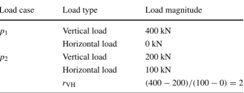
Table 1 Calculation example of parameterrVH, wherepi represents theith load case
Load case Load type Load magnitude
p1 Vertical load 400 kN
Horizontal load 0 kN
p2 Vertical load 200 kN
Horizontal load 100 kN
[image:4.595.307.545.623.714.2]Using the superposition approach, the optimum structure for all four load cases can be obtained by superimposing the optimal layouts for each of the four individual component load cases. Referring to Fig.1c, it is obvious that the optimal layout for load casep1 will be vertical columns running along the outer edges of the domain. Also, it is obvious that the optimal layout for load casep4will comprise no members at all (since there are no applied loads). Therefore, the optimal bracing layout can be obtained simply by superimposing the optimal layouts arising from load cases
p2andp3, each obtained using the basic single load case
(a)
(b)
Fig. 2 Numerical verification of superposition approach:aexample withrVH=3;bexample withrVH=6, whererVHis the parameter
governing layout for multiple load case problems. On the left hand side are optimized results from single component load casesp2and
p3, see Fig. 1c, and on the right hand side are multiple load case results. Red and blue bars represent, respectively, members taking tensile and compressive forces. For the multiple load case results, the force distribution shown corresponds to the load case with horizontal (lateral) loads acting from left to right
layout optimization formulation, Eq. (1). As these latter layouts depend only on V and H, a new parameter
rVH = V /H can be introduced as the parameter that
controls the form of the optimal layout. Table 1 shows a sample calculation of rVH. To verify the correctness of
the superposition approach described, solutions were also obtained for sample problems using the standard multiple load case LP formulation, as shown in Fig.2(details of the formulation are given in Appendix2).
The finding that there is a parameterrVH which governs
the optimal layout is significant. Since different design codes stipulate that different combinations of loads are involved in the various load cases to be considered, this indicates that the optimal layout will be strongly influenced by the choice of design code. This fact is unlikely to have been anticipated by the code writers.
3 Examples: simple single and multi-storey
braced frames
In this section, examples of the relationships betweenrVH
and the optimal layout are presented for two types of braced bay, one with loading applied only at the top corners of
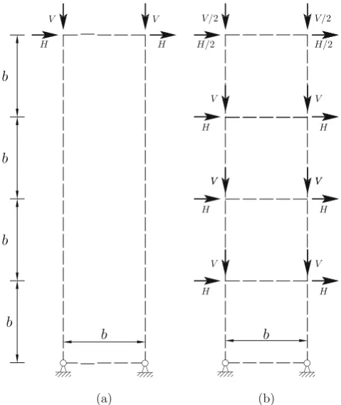
Fig. 3 Loads for single- and multi-storey bracing layout optimization study:asingle-storey cases;bmulti-storey cases; values ofV andH
[image:5.595.77.266.220.620.2] [image:5.595.305.545.394.679.2]Layout optimization of building frames subject to gravity and lateral load cases
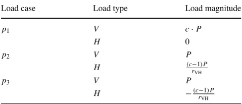
Table 2 Load values ofV andH in different load cases, where pi represents theith load case; P is a reference load; cis a loading coefficient, assumed to be 1.35 based on British Standard 5950-1:2000 load case combinations, see Eq. (2a–2c);rVHis the parameter
governing layout for multiple load case problems (load positions are shown in Fig.3)
Load case Load type Load magnitude
p1 V c·P
H 0
p2 V P
H (c−rVH1)P
p3 V P
H −(c−rVH1)P
the design domain, and the other with the frame split into square vertical bays with loading at each ‘floor’ level. The numerical multiple loading layout optimization approach described in Appendix2is used.
3.1 Problem definition
Figure 3 shows the design domain and load and support conditions for the cases considered in this study. For sake of simplicity, the aspect ratio of the design domain of all cases has been fixed to 4:1. Table2presents the values of the load parameterVandHin Fig.3. In the study,V is kept constant but the horizontal loadH is varied, replicating a changing external environment. For the vertical loadV defined by the
British Standard the ratio of the vertical load in the gravity and wind load cases can be denotedc, where:
c= 1.4Gk+1.6Qk
1.0Gk+1.2Qk
=1.33+ 0.07Gk
1.0Gk+1.2Qk
(3)
Therefore, from (3), it is clear that cmin = 1.33 when
Gk=0 andcmax=1.40 whenQk=0. This means that the
horizontal loadH equals (c−r1)P
VH and−
(c−1)P
rVH in load cases
p2 andp3 respectively, whereP is a reference load (see
Table2). For the examples documented,chas been taken as 1.35, though with checks later undertaken using c =1.33 andc=1.40 to verify that the main findings were largely unaffected by this choice.
The volumes of the optimized layouts are compared with two other layouts: standard cross bracing and the modified layout identified by Stromberg et al. (2012). Note that Stromberg et al. (2012) studied both problems involving multiple horizontal loads applied through the height of a building and problems involving only a single horizontal load applied to the top of a building, the latter resembling the cantilever problem considered in Section 4.8 of Hemp (1973). Since the structures obtained in both cases were found to be similar, the same Stromberg module layout is used here for both single- and multi-storey problems. (Note that members are re-sized for each specific case.)
3.2 Optimal layout results
Figures4and5show the optimal layouts and corresponding normalized volumes for the single and multi-storey frames
Fig. 4 Single-storey frame example: comparison of volumes and opti-mized layouts based on British Standard loading withc= 1.35 and
rVH =(0.4Gk+0.4Qk)/(1.2Wk), wherecis the ratio of the vertical
load between load cases (i.e.(1.4Gk+1.6Qk)/(1.0Gk+1.2Qk)); all
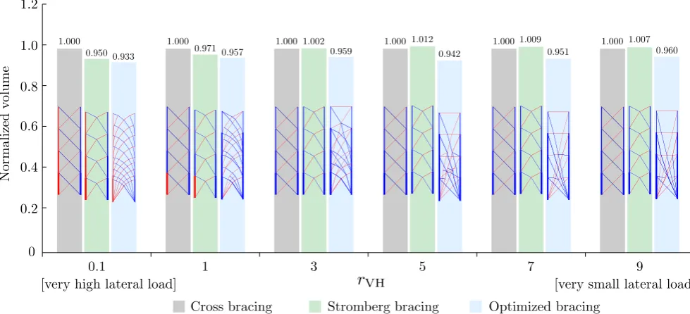
Fig. 5 Multi-storey frame example: comparison of volumes and opti-mized layouts based on British Standard loading withc= 1.35 and
rVH = (0.4Gk+0.4Qk)/(1.2Wk), wherecis the ratio in vertical
load between load cases (e.g.(1.4Gk+1.6Qk)/(1.0Gk+1.2Qk)); all
volumes are normalized against the volumes of standard cross brac-ing systems; red and blue bars represent, respectively, members takbrac-ing tensile and compressive forces when lateral loads are applied from left to right
described in Section3.1. Note that simple (pinned) frame connections have been assumed in the models.
Firstly, as expected, the optimized bracing can be observed to always be more efficient (i.e. to consume less material) than both standard cross bracing and Stromberg bracing. However, the differences between the normalized volumes of the different layouts are comparatively small (maximum difference is 7%). This is partly because the nor-malized volume includes both the volume of vertical columns and the volume of interconnecting bracing elements.
Secondly, it is clear that asrVH increases, the optimized
layouts tend to include highly inclined members to transmit the applied vertical loading more directly towards the supports. This is at variance with the finding by Lu et al. (2018), who suggest that there should be a 45◦intersection
angle between columns and bracing member pairs; however, this observation only applies if the columns are assumed to have infinite reserves of strength, which is not the case here.
Thirdly, it is clear that whilst Stromberg bracing is more efficient than standard cross bracing when rVH is low, the
situation is reversed whenrVH is high. This is a result of
the fact that the shallow inclined members of the Stromberg bracing layout are most suitable for cases when horizontal (lateral) loads are significant. In such cases it can be observed that Stromberg bracing has a much simpler layout than the optimized layouts, but the associated volume is only slightly higher. This suggests that Stromberg bracing provides a very practical solution for cases when horizontal (lateral) loads are significant.
[image:7.595.51.541.61.284.2] [image:7.595.231.544.568.719.2]Layout optimization of building frames subject to gravity and lateral load cases
Table 3 Small office building: characteristic actions
Actions on roof Actions on floors
Permanent action 0.9 kN/m2 3.7 kN/m2
Variable action 0.6 kN/m2 3.3 kN/m2
Wind action 89.5 kN 187.1 kN
4 Bracing design of a small office building
Here, the optimization of a four-storey steel frame structure for a small office building is considered. In this caserVH
was calculated to be 0.68 and 2.33 for the major and minor wind directions respectively.
Lateral stability of the frame is provided by the presence of braced bays through the full height of the frame (Fig.6
shows a typical plan above ground floor level; the height between floors was 4.5m). Actions applied to this structure are shown in Table3. Load cases for a braced bay are here assumed to be based on British Standard loads, defined in Eq. (2a–2c). For the sake of simplicity only the wind load case acting normal to the long side of the building, and the design of the bracing resisting this load is considered in the design. The steel has a yield stress of 355MPa in both tension and compression and an elastic modulus of 205 GPa.
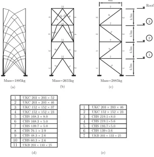
The optimized bracing design is shown in Fig. 7a. To permit comparison, a conventional design is shown in Fig. 7c, depicting the bracing layout presented for the same building by Brettle and Brown (2009). Since the structure shown Fig. 7a is too complex to be fabricated using conventional approaches, a more practical alternative design was also sought. To achieve this the horizontal beams used in the conventional design (Fig.7c) were used as pre-existing members, and a new optimization run. This yielded the intermediate optimized design shown in Fig.7b.
To achieve the conventional design shown in Fig. 7c, Brettle and Brown (2009) kept the sizes of all columns and bracing members constant throughout the height of the frame, even though the forces in the members reduce significantly from ground to top floor. This kind of rationalization is common in practice. However, to remove the associated inefficiency, and hence to provide a fair comparison with the optimized layouts, here the members were resized, with the chosen sections being the most efficient H-section column and circular hollow sections available in the UK (Tata Steel Europe Limited2016).
To realize the optimized designs shown in Fig.7a and b a two-stage process was adopted. Firstly, layout optimization and geometry optimization were used to find the optimal layout of the braced bay (the 6m wide four-storey right hand
Fig. 7 Small office building:
aoptimized braced bay design;
boptimized design with pre-existing beams;
cconventional braced bay;
dsections chosen for the structure shown inb, with buckling effects considered;
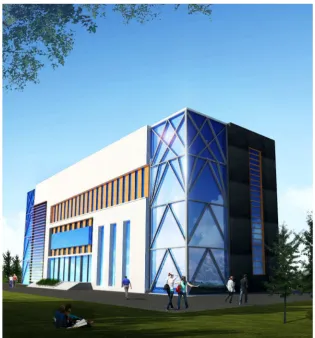
[image:8.595.229.544.397.719.2]Fig. 8 Small office building: visualization of building incorporating optimized braced bay shown in Fig.7b
bay shown in Fig. 6) and associated volume of required material (these were 0.0900m3and 0.0976m3for the layouts shown in Fig.7a and b respectively, compared with 0.1032m3 for the layout shown in Fig. 7c). Secondly, in a post-optimization rationalization step the column and inclined bracing members were each assigned the most efficient Tata Steel section to transmit the required load, taking account of member buckling effects in compression members as necessary. The total steel masses of the resulting optimized bracing systems are shown in Fig.7. The structure shown in Fig.7a has the lowest mass, representing a 35% material saving compared to the conventional design shown in Fig.7c (this is greater than the reduction prior to the post-optimization rationalization, of 13%, which in turn exceeds the reductions found previously due to the comparative inefficiency of the layout shown in Fig.7c).
In addition to the strength of the bracing system, the stiffness of the frame is also checked. Linear elastic static analyses were conducted as a post-processing step for the three cases, considering load case (2b). The tip displacements for the designs shown in Fig.7a, b and c were found to be 55.1 mm, 44.5 mm and 57.7 mm respectively, which all satisfy the design code requirements (for details see Appendix3).
The optimized structure shown in Fig. 7b has a much simpler layout than the optimized benchmark structure (Fig.
7a) and is more structurally efficient than the original design proposed by Brettle and Brown (2009). Therefore, the structure shown in Fig.7b may provide a fair compromise between efficiency and practicality in this case. Figure 8
shows a visualization of how this could look in reality.
5 Conclusions
Layout optimization has been used to identify optimal layouts for building frames. The following conclusions can be drawn:
1. The optimal layouts obtained using the ‘holistic’ strategy adopted differ from those obtained when seeking to brace a frame comprising pre-existing members (e.g. as considered by Lu et al.2018). 2. For the simple holistic design problems involving
[image:9.595.230.546.58.397.2]Layout optimization of building frames subject to gravity and lateral load cases
3. When one of the applied load cases involves no lateral load, the optimal layout was found to be controlled by a parameter rVH, whererVH =V/H and V and H represent respectively the differences in vertical and horizontal load between the load cases.
4. Since different design codes stipulate different com-binations of loads are present in the load cases to be considered, this indicates that the optimal layout will be influenced by the choice of design code. This outcome is unlikely to have been anticipated by the code writers. 5. The bracing layout presented by Stromberg et al. (2012) has been found to be very efficient in cases where the horizontal load dominates (e.g. rVH < 3). However,
standard cross bracing becomes more efficient when the vertical load dominates (e.g.rVH≥3).
6. Adopting a holistic design strategy, in which non-vertical members are allowed to carry gravity loads as well as act as bracing members, appears to be most worthwhile in cases where the vertical load dominates (e.g.rVH ≥5).
7. Layout optimization has been applied to the design of the frame of a small four storey office building comprising rectangular bays. This led to an uncon-ventional frame layout and a reduction in the volume of material required compared with the conventional layout considered (13% prior to the post-optimization rationalization).
6 Replication of results
The main findings from this work can be reproduced by using numerical layout optimization to solve the example problems described.
Acknowledgements The second and third authors acknowledge the support of EPSRC, under grant reference EP/N023471/1. The authors are also grateful to an anonymous reviewer for making a suggestion that enabled Appendix1to be greatly simplified.
Compliance with Ethical Standards
Conflict of interest The authors declare that they have no conflict of interest.
Open Access This article is distributed under the terms of the Creative Commons Attribution 4.0 International License (http:// creativecommons.org/licenses/by/4.0/), which permits unrestricted use, distribution, and reproduction in any medium, provided you give appropriate credit to the original author(s) and the source, provide a link to the Creative Commons license, and indicate if changes were made.
Appendix 1: Application of principle
of superposition
A superposition approach can be used to obtain the opti-mization solution for multiple load cases via superimposing
the optimization solutions of certain single component load cases. Hemp (1973) first demonstrated that this approach could be applied with two arbitrary load cases and it was later expanded by Rozvany and Hill (1978) to be suitable for problems with more than two load cases for materials with equal permissible stresses in tension and compression. Nevertheless, in situations with more than two load cases, certain conditions need to be fulfilled for the superposition approach of Rozvany and Hill (1978) to be valid. Rozvany and Hill’s method involves the replacement of the actual load cases with associated ‘component’ load cases. In a sit-uation with four alternative load cases (e.g.p1,p2,p3and p4), there exist four component load cases according to the
superposition approach (e.g.p1,p2,p3andp4) and each of them could be obtained based on the original four alternative load cases using (4).
p=1
4
⎡
⎢ ⎢ ⎣
1 1 1 1 1 −1 1 −1 1 1 −1 −1 1 −1 −1 1
⎤
⎥ ⎥ ⎦
p, (4)
wherep= {p1, p2, p3, p4}is the vector of component load
cases;p= {p1, p2, p3, p4}is the vector of alternative load
cases.
Rozvany and Hill (1978) demonstrated that, if one of several specific conditions is met at every point in the design domain, then the superposition approach can be applied. For the current problem, which has four load cases, Condition 1 is relevant (referred to as Condition (10c) in Rozvany and Hill1978).
Condition 1 requires, at any arbitrary point in the design domain, the stress generated by at least one of the component load cases to be zero.
Here, since every point in component load casep4has zero stress (e.g. see Fig.1c), and given the the method used to obtain component load cases, the superposition principle is applicable. Thus, the superposition approach has been used to derive the optimized result in the case considered in Fig.1b.
Appendix 2: Multiple load case plastic layout
optimization formulation
The LP plastic truss layout optimization problem formu-lation for problems involving multiple load cases can be written as:
min V =lTa
subject to Bqα=fα a≥0
ai≥ {qi+/σ
+
i +q
−
i /σ
−
i }α
{qi+}α,{qi−}α≥0
whereα = 1,2,..., M andi = 1,2,..., m; and M,m,n
represent, respectively, the number of load cases, members and nodes of the design problem; V represents total structure volume, a = {a1, a2,..., ai}, l = {l1, l2,..., li},
B is a suitable (2n × 2m) equilibrium matrix, qT =
{q1+,−q1−,..., qm+,−qm−},fαis the load case vector, where
fα = {f1x, f1y,..., fnx, fny}α; and ai, li, qi+, q
−
i , σ
+
i , σ
−
i
represent, respectively, the cross section area, length, tensile force, compressive force, tensile stress capacity and compressive stress capacity of member i and also {fjx}α
and {fjy}α represent, respectively, the x and y direction
component load applied on nodej in load caseα.
In the resent contribution, the adaptive member adding method for multiple load case problems proposed by Pritchard et al. (2005) has been employed to reduce compu-tational cost and the geometry optimization rationalization scheme proposed by He and Gilbert (2015) has been used to simplify the resulting layouts.
Appendix 3: Influence of second order effects
One main function of bracing is to control the second order effects induced by lateral displacements. Here, the practical design example described in Section4will be considered.
Eurocode 3 (2006) uses a parameterαcr to account for
second order effects. An approximate formula for αcr is shown in (6). Eurocode 3 stipulates that, using an elastic analysis, if αcr > 10, then second order effects can be
neglected. If 3 > αcr > 10, then the amplification factor given in (7) must be applied to the horizontal load. Ifαcr <
3, then a global second order effect analysis must be carried out.
αcr=
H Ed VEd h δH,Ed (6)
Amplification factor= αcr
αcr−1
(7)
whereHEdis the total horizontal reaction at the bottom of
the storey,VEd is the total design vertical load applied on
the storey, h is storey height and δH,Ed is the horizontal
displacement at the top of the storey, relative to the bottom, calculated using an elastic analysis.
For each structure shown in Fig.7values forαcrcan be
obtained for each storey and the minimum of these found. The minimumαcr values for Fig.7a, b and c were found
to be 19.20, 27.55 and 23.47 respectively. Since all these values are larger than 10, then, according to Eurocode 3, second order effects can be neglected.
In some circumstancesαcr may drop below 10. In this
case the amplification factor shown in (7) can potentially be
employed during the layout optimization process to obtain an acceptable design.
References
Brettle ME, Brown DG (2009) Steel building design: worked examples for students. The Steel Construction Institute
BS EN 1993-1-1 (2006) Eurocode 3: Design of steel structures. Part1-1: General rules and rules for buildings
Burry J, Felicetti P, Tang J, Burry M, Xie M (2005) Dynamical structural modeling: a collaborative design exploration. Int J Archit Comput 3(1):27–42
Carroll C, Cross P, Duan X, Gibbons C, Ho G, Kwok M, Li R, Lee A, Li R, Luong A, Pope C (2008) Case Study: CCTV Building-Headquarters & Cultural Center. CTBUH Journal, Issue III Chan CM, Grierson DE, Sherbourne AN (1995) Automatic optimal
design of tall steel building frameworks. J Struct Eng 121(5):838– 847
Dorn WS, Gomory RE, Greenberg HJ (1964) Automatic design of optimal structures. Journal de Mecanique 3:25–52
Foster and Partners (2005) Modeling the Swiss Re Tower. Architecture Week, 4 May
Gilbert M, Tyas A (2003) Layout optimization of large-scale pin-jointed frames. Eng Comput 20(8):1044–1064
He L, Gilbert M (2015) Rationalization of trusses generated via layout optimization. Struct Multidiscip Optim 52(4):677–694
Hemp WS (1973) Optimum structures. Oxford Engineering Science Series. Clarendon Press
Kim C, Kim H, Hwang J, Hong S (1998) Stiffness-based optimal design of tall steel frameworks subject to lateral loading. Struct Optim 15(3-4):180–186
Liang QQ, Xie YM, Steven GP (2000) Optimal topology design of bracing systems for multistory steel frames. J Struct Eng 126(7):823–829
Lu H, Gilbert M, Tyas A (2018) Theoretically optimal bracing for pre-existing building frames. Struct Multidiscip Optim 58(2):677–686 Moon KS, Connor JJ, Fernandez JE (2007) Diagrid structural systems for tall buildings: characteristics and methodology for preliminary design. Struct Des Tall Spec Build 16(2):205–230
Pritchard T, Gilbert M, Tyas A (2005) Plastic layout optimization of large-scale frameworks subject to multiple load cases, member self-weight and with joint length penalties. In: 6th World Congress of Structural and Multidisciplinary Optimization, CD-ROM proceedings, 10 pages
Rozvany G, Hill R (1978) Optimal plastic design: superposition principles and bounds on the minimum cost. Comput Methods Appl Mech Eng 13(2):151–173
Rozvany GI, Sok´oł T, Pomezanski V (2014) Fundamentals of exact multi-load topology optimization–stress-based least-volume trusses (generalized Michell structures) - Part I: Plastic design. Struct Multidiscip Optim 50(6):1051–1078
Stromberg LL, Beghini A, Baker WF, Paulino GH (2012) Topology optimization for braced frames: combining continuum and beam/column elements. Eng Struct 37:106–124
Tata Steel Europe Limited (2016) Tata Steel sections interactive ‘Blue Book’. The Steel Construction Institute
Ter´an-Gilmore A, Coeto G (2011) Displacement-based preliminary design of tall buildings stiffened with a system of buckling-restrained braces. Earthq Spectra 27(1):153–182