DESIGN, DEVELOPMENT AND TEST OF MICROSTRIP ANTENNA FOR SHORT RANGE COMMUNICATION
NUR ASHEERA BINTI BASARUDDIN
This Report is submitted
in Partial Fulfilment of Requirement for Award of
Bachelor of Electronic Engineering (Telecommunication Engineering) With Honours
Faculty of Electronics and Computer Engineering
UNIVERSITI TEKNIKAL MALAYSIA MELAKA
V
DEDICATION
Special dedication to my lovely parents, Basaruddin bin Taib and Nor Hashimah binti Hashim, my siblings, my kind hearted supervisors Dr. Noor Azwan Bin Shairi
VI
ACKNOWLEDGEMENT
Alhamdulillah, all Praise to thank Allah SWT the Almighty for giving me the Rahmah to finish my final year project.
I would like to thank to God because I manage to complete my final year project without major hiccup. I am indebted to both of my supervisors Dr Noor Azwan Bin Shairi and Dr Imran Bin Mohd Ibrahim of thier priceless effort in assisting me whenever I find difficulties in completing my task and for reviewing my report and comments in improving this report. I specially thank to my family, especially my lovely parents, Basaruddin Bin Taib and Nor Hashimah Binti Hashim for the continuous support throughout my day and to my friends for their time, concern, efforts and always encouraging me when preparing this report. A word of thanks to everybody that involve in my project directly or indirectly. Not forget to Universiti Teknikal Malaysia Melaka (UTeM) for the opportunity given.
VII
ABSTRACT
VIII
ABSTRAK
IX
LIST OF TABLES
TABLE TITLE PAGE
1 RFID bands applications 11
2 Operating frequencies of some countries 13
3 Tecnical requirements for short range devices (SRD) 18
4 Frequency Band 27.5 - 29.5 GHz Allotted for LMCS
from MCMC s
19
5 Increasing number of array 31
6 Classification of RFID tags 35
7 Summary of discussed papers 35
8 Dimension of the antenna 36
9
Comparison of the bandwidth and the peak of realized gain of different antennas (MSF is short for modified Seirpinski)
39
10 FR4 specifications 49
11 Specification of substrate parameter 52
12 Specification of antenna parameter 53
13 Parameter for the single patch antenna 54
14 Parameter for 1x2 array patch antenna 55
15 Parameter for 2x2 array patch antenna 56
16 Comparison Between Measurement and Simulation on Return Loss 64
17 Comparison result of the simulation return loss of the
antenna
69
18 Comparison result of the simulation gain of the antenna 72
X
LIST OF FIGURES
FIGURE TITLE PAGE
1 Antenna 4
2 Antenna as a transition device 5
3 Radiation Pattern in polar and Cartesian coordinate 14
4 Different shapes of microstrip antenna 20
5 Microstrip antenna 21
6 Microstrip feed at radiating edge 26
7 Gap-Coupled nicrostrip feed 27
8 Inset feedline 27
9 Non radiating edge 27
10 Array antenna 29
11 Proposed of E shaped CP Microstrip antenna 32
12 Schematic configuration of the proposed compact
arrowhead-shaped slot antenna
33
13 Simulated return loss against frequency for the square
antenna with triangular slot, concentric slot and proposed arrowhead-shaped slot
34
14 Geometry design of the proposed antenna 37
15 Ground length vs return loss 38
16 HFSS model of modified Sierpinski fractal antenna 39
17 Flow chart of project report 43
18 Flow chart of working progress 44
19 Conversion of the antenna design into coral drawing 50
20 CST studio suite 2016 51
XI
22 Front view of designed single patch antenna 54
23 Front view of designed 1x2 array patch antenna 55
24 Front view of designed 2x2 array patch antenna 56
25 The prototype of microstrip array patch antenna 57
26 Hyperterminal 59
27 Testing the antenna signal 60
28 Measurement result for the return loss 63
29 Comparison Between Measurement and Simulation on
Return Loss
64
30 Realized gain of the simulated antenna 65
31 Far field of the designed antenna 66
32 Simulation result for the return loss for a single patch
antenna
67
33 Simulation result for the return loss for a 1x2 array patch
antenna
68
34 Simulation result for the return loss for a 2x2 array patch
antenna
68
35 Comparison result of the simulation return loss of the
antenna
69
36 Simulation result for single patch antenna 71
37 Simulation result for 1x2 array patch antenna 71
38 Simulation result for 2x2 array patch antenna 72
39 Simulation result for radiation pattern 74
XII
LIST OF ABBREVIATIONS
RFID - Radio Frequency Identification Device
UHF - Ultra-High Frequency
MWF - Microwave Frequency
CST (MWS)
- Computer Simulation Technology (Microwave studio)
Γ - Reflection Coefficient
VSWR - Voltage Standing Wave Ratio
RL - Return Loss
dB - Decibels
RF - Radio Frequency
LF - Low Frequency
HF - High Frequency
ERP - Effective Radiated Power
dBi - Decibels relative to isotropic
1
CHAPTER I
INTRODUCTIONS
2
1.1 PROJECT BACKGROUND
A catastrophic event is a major adverse event resulting from natural processes of the earth; example floods, hurricane, tornadoes, volcanic eruptions, earthquakes,
tsunamis and any other geologic processes.
A natural disaster can bring about death toll or property damage and regularly leaves some economic harm afterward, the seriousness of which relies on the influenced population’s versatility or capacity to recoup and also on the infrastructure available.
A person who has been through a natural disaster will find out how difficult it is to establish communication immediately after. Usually power is down and landline communications are interrupted due to tower loss and other technical difficulties.
Christina Richards in her paper reported that a sudden and a wide scale breakdown or interruption of the communication infrastructure will be one of the most immediate impact during the flood and any natural disaster. The bad impact can be widely felt when the public communication fail. It also has the ability to wipe out access to standard mobile or landline telecommunications, in addition to internet and even satellite-based emergency communication devices [11].
Whether these systems are completely or just partially knocked off offline, communications systems during a natural disaster can be the difference between life or death for those affected. Locating those who may be trapped or injured becomes standard methods of communication [11].
Even though we live in an extremely technological era, an alternative communication system during disaster is an absolute necessity in such times. Rescue teams use their systems to get in touch with people who have been isolated.
B.S Manoj and Alexandra Hubenko said that a primary challenge in responding to both natural and man-made disasters are communications. A problem frequently cited by responders is the lack of radio interoperability [17].
3
all their family members are safe as well. Also there are situations when family members get separated.
Communications Infrastructure fails during a disaster will eventually cause physical damage to network devices and network congestion. Physical damage can create physical disturbance that can bring damage to the cities and communications equipment. If a cell tower is severely damaged, it will cause major disruptions in the area’s wireless communication. When disaster strikes, the ‘pipes’ that make up our communications networks often become congested [11].
The main technological challenge after a disaster is rapid deployment of communication system for first respondent and disaster management. This concluded to be true regardless of when the communication network has been completely destroyed (power, telephone, and/or network connectivity infrastructure) [17].
4
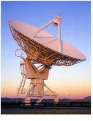
1.1.1 Antenna
[image:16.595.244.396.278.475.2]An antenna is defined “a usually metallic device for radiating or receiving radio waves.” In other word the antenna is the transitional structure between free-space and guiding device. The guiding device or transmission line may take the form of the coaxial line or a hollow pipe (waveguide), and it is used to transport electromagnetic energy from the transmitting source to the antenna, or from the antenna to the receiver. In former case, we have a transmitting antenna and in the latter a receiving antenna [18].
Figure 1 : Antenna
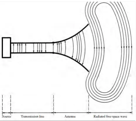
5
Figure 2: Antenna as a transition device
There are many types of high directional antenna such as :
i) Parabolic antenna
ii) Yagi Uda antenna
iii) Horn antenna
iv) Phase array antenna
1.2 OBJECTIVES AND SCOPE OF PROJECT
6
1.2.1 Project Objectives
This project is carried out on the following objectives :-
To design, develop, test and validate the micro strip patch antenna at the frequency of 915MHz for short range communication system within nearest radius, with the gain of 5dBi.
1.2.2 Scopes of project
This project is carried out based on the following scopes of project :-
(i) This purpose of this project is to design, develop, test and validate the micro strip patch antenna performance for short range communication system. (ii)To test the antenna at outdoor.
(iii)To test the micro strip patch antenna at the frequency of 915MHz. (iv)To use the CST to design the antenna and fabricate the FR4 substrate.
(v) To produce a minimal size antenna with 5dBi.
1.3 PROBLEM STATEMENT
A person who has been through a natural disaster will find out how difficult it is to establish communication immediately after. One of the immediate and significant impact of flooding and natural disasters is a sudden and wide-scale breakdown or interruption of communication infrastructure. The power is down and landline communications are interrupted due to tower loss and any other technical difficulties. When public communication network fail, the impact can be widely felt and has the ability to wipe out access to standard mobile or landline telecommunications.
7
project will also focus on ways to communicate like texting or messaging during natural disaster directly without having to pass through the base station. This project will also develop antenna and provide coverage within 1km radius.
Problem arises when the frequency proposed which is 915MHz will eventually produce a large size of antenna; and eventually the antenna will become heavy. This project tends to develop and produce a light weight antenna with only full-palmed size but yet still manage to provide a good gain of 5 dBi within the nearest radius and lastly compatible to be used on the mobile device. Overall, this project will focus on the short range communication during the natural disaster by introducing the off grid communication.
1.4 SYSTEM OPERATIONS
Studying about the antenna has been one of the crucial task of this project. It has become parts of the literature review in order to determine the best way in designing the specifications of the antenna and hence to complete all the calculations needed to produce the gain aimed in this project.
Besides antenna’s knowledge is needed, in this project software development using the CST is used in order to design variation types of antenna in order to meet the specifications stated. Integrate the result from the CST with the FR4 substrate fabricated, as the part of the hardware development. Properties of antenna and the variations in designing antenna including the calculations requirement were studied especially on how to synchronize the designs of the antenna to get the gain and reach within the radius expected in the objective of this project.
8
1.5 ORGANIZATION OF THESIS
9
CHAPTER II
LITERATURE REVIEW
10
2.1 INTRODUCTIONS
The works from other researchers had been explained into this chapter that is related to the design and development of this project which is “Design, development and test of micro strip antenna for short range communication”. This project is successfully developed by continuously doing the literature review until it is completed with the antenna design. By doing the comparison with several types of antennas that had been developed at 923MHz.
Antenna is device that converts a guided electromagnetic wave on transmission line into a plane wave propagating in free space. Along this line, one side of antenna shows up as electrical circuit component, while the opposite side as an interface with proliferating plane wave. Antenna can be used for both transmit and function [18].
A variety of antenna have been developed for different functions. They are the wire antennas, aperture antennas, printed antennas and lastly the array. Wire antenna is used at low frequency such dipole, monopole and horns. Aperture antenna are mostly common used at microwaves and millimeter wave frequency (rectangular and waveguide). Lastly is the array antenna which consists of regular arrangement with feed network.
2.2 RADIO FREQUENCY IDENTIFICATION (RFID)
11
[image:23.595.114.527.260.575.2]In recent years, radio-frequency identification (RFID) technology has been expansively integrated into modern society applications, ranging from barcode replacement to remote monitoring sensing and healthcare [16]. RFID systems in an ultra-high frequency (UHF) band have become a popular technology in several commercial applications, eg., retail and consumer packaging, industrial and manufacturing, security and access control, transportation, and distribution systems [15].
Table 1 : RFID bands applications [14]
Types of frequency Frequency Applications
Low frequency (LF) 30-300 KHz 1. Implant in trees
2. Animal tracking
High frequency (HF) 3-300 MHz 1. For short up ranges, with metal
and water not influencing the signs.
Ultra high frequency (UHF)
300 MHz- 3 GHz
1. Offers better read ranges with
speedier perusing speeds.
2. Uses more power and more
improbable through material Super high frequncy
(SHF)
2.4-2.48 GHz 1. Avoid impedance from metal and
water.
2. Practically used for climate
monitoring and pallet.
12
M. H. Ariff, I. Ismarani and N. Shamsuddin, in their journal revealed that a reader (also called the RFID interrogator) is basically a transceiver that reads the substance of RFID tags in a region. They included that the most extreme separation between the reader’s antenna and the tag vary, contingent upon the application. Likewise, the role of the antenna for reader and tag are very imperative. The antenna enables the chip to transmit the data that is utilised for identification. Lastly the authors detailed that the RFID reader with the circular polarized antennas radiate in a 90 degree pattern and are less delicate to the tag’s introduction on the package [14][5].
Anil Kr Gautam in his paper revealed that ordinarily an RFID device system operates in UHF band (902 MHz-928 MHz). He additionally announce that to get the most proficient RFID system, because of the irregular orientation of the tags in real applications, a circularly polarized antenna is required for the RFID reader. Thus an RFID antenna must have circular polarized radiation pattern to enable the information transmission to be autonomous of the orientation of the transmitter and the receiver as well as reduction in the loss brought on by the multipath effects between the reader and the tag antenna [15].
There are several frequency bands used in RFID which are low frequency (LF), high frequency (HF), ultrahigh frequency (UHF) and microwave. Neha Saini and Vijay Kumar in their paper also reported that owing to its longer read range, higher data transmission rate as well as larger storage capacity, UHF system are gaining more popularity compared to other system [12].
In recent years, there are many sorts of outlined antenna produced for hand-held RFID reader, for example :
1. Helical antenna [13]
2. Loop antenna [19]
3. PIFA antenna [31]
4. Monopole antenna [32]
5. Three elements printed Yagi antenna [33]
![Table 1 : RFID bands applications [14]](https://thumb-us.123doks.com/thumbv2/123dok_us/66903.6314/23.595.114.527.260.575/table-rfid-bands-applications.webp)