Int. J. Electrochem. Sci., 12 (2017) 7829 – 7843, doi: 10.20964/2017.08.20
International Journal of
ELECTROCHEMICAL
SCIENCE
www.electrochemsci.org
Efficient Epoxidation of Alkenes with Hydrogen Peroxide and
Electrochemical Behavior in Water Over Heteropolymolybdate/
Silica Nanocomposite
Hossein Salavati*,Abbas Teimouri
Department of Chemistry, Payame Noor University (PNU), 19395-3697, Tehran, I.R. IRAN
*
E-mail: [email protected]
Received: 14 February 2017 / Accepted: 25 May 2017 / Published: 12 July 2017
A (PVMo/SiO2) nanocomposite catalyst was synthesized by immobilization of vanadium substituted
heteropolymolybdate (PVMo) in mesoporous silica. The nanocomposite catalyst was characterized by different physico-chemical techniques such as elemental analysis, FT-IR, UV-Vis, XRD, SEM, TEM, BET and cyclic voltammetry. The PVMo/SiO2 nanocomposite catalyst was used for alkene
epoxidation with H2O2 as oxidant, under agitation with magnetic stirring and ultrasonic irradiation.
Effect of reaction parameters such as amount of oxidant and catalyst, reaction temperature and intensity of ultrasonic irradiation were studied. This catalyst can be recovered several times with little failure of its activity. The obtained consequences explained that the catalytic activity of the nanocomposite (PVMo/SiO2) was upper than that of chaste heteropolymolybdate..
Keywords: Heteropolyanion, nanocomposite, epoxidation, Ultrasonic irradiation.
1. INTRODUCTION
In surface type catalysis, the reactions occur on the inner pore and outer surfaces of solid catalysts. In general, the reaction speed is comparative to the catalyst surface area. A valuable process for improving catalytic show in liquid-solid and gas-solid shell heterogeneous reactions is to maintain the heteropoly compounds on solids with lofty surface area. Other benefits of using supported heteropoly compounds as catalysts are their acceptance of improvement and recycling after operation liquid phase reactions, and the easier separation of produce than that of the homogeneously catalyzed reactions. Fundamental solids such as Al2O3 and MgO as support have a tendency to decay the
heteropoly compounds [10-12]. Acidic or neutral substances such as SiO2 [13-19], active carbon [20],
TiO2 [21], ZrO2 [22], Polyaniline [23] are appropriate supports. Mesoporous silica has been
established to be able to trap heteropoly acids, obtained elevated catalytic activity [24, 25]. Keggin-type transition metal substituted heteropolyoxoanions have some valuable properties that create them very good-looking as redox catalysts for roundabout electrochemical processes, such as
1. Elevated constancy in acidic media and inertness in the direction of reactive intermediates
2. Option to modify the official potential of the transition metal which is included into the polymetalate construction by altering the nature of the middle heteroatom;
3. Presence of extremely oxidized metallic centers, stabilized by the negatively charged polyoxo ligand, and extremely helpful in oxidation processes;
4. Incidence of an inner sphere electron transfer mechanism during the free co-ordination orbital of the transition metal [26].
In this research we expand our current study [18, 27-30]. Herein, we explain the synthesis and characterization of a new nanocomposite, consisting of vanadium substituted heteropolymolybdate Na5PV2Mo10O40 (PVMo), supported on mesoporous silica. Under reflux and ultrasonic irradiation
situations, supported and non-supported PVMo have been employed as catalysts for alkene epoxidation with hydrogen peroxide (Scheme 1).
Scheme 1. Oxidation of alkenes using PVMo/SiO2 catalyst
2. EXPERIMENTAL
2.1. Materials and methods
silica used for support was Cab-oSil® M5 and prepared from Riedel-deHaen(Mesh 44 microns and Average particle length 0.2-0.3 microns). All other solvents and chemicals were bought from Merck Company and were obtained Cyclooctene, Cyclohexene, Indene, Methylstyrene, Acetophenone, α-Pinene, 1-dodecene, 1-octene.
Elemental analysis was performed on Perkin-Elmer NexIon 350 ICP-MS spectrometers. (Atomic Absorption analysis was carried out on a Shimadzu 120 spectrophotometer. Diffuse reflectance spectra (DRS) were recorded on a Shimadzu UV-265 apparatus with optical grade BaSO4
as reference. Fourier-transformed infrared (FT-IR) spectra were obtained as potassium bromide pellets in the range of 400-4000 cm-1 with Nicolet-Impact 400D apparatus. Scanning electron micrographs (SEM) of the catalyst and support were taken on SEM Philips XL 30. Powder X-ray diffraction (XRD) information were obtained on a D8 Advanced Bruker, using Cu Kα radiation (2θ=5-70˚). Gas
chromatography (GC) experiments were performed with a Shimadzu GC-16A apparatus, using a 2 m column packed with silicone DC-200 or 20 m Carbowax. In all experiments the N-decane was used as internal standard. 1H NMR spectra were recorded on a Bruker-Arance AQS 300 MHz. CDCl3 and
tetramethylsilane (TMS) were used as a solvent and an interior reference. Conversions and yields were obtained by GC experiments and the products were recognized after separation and purification. Cyclic voltammetric (CV) studies were performed with an Auto Lab 30 instrument.
2.2. Preparation of the PVMo/SiO2 nanocomposite
To a solution of 0.1 g vanadium substituted heteropolymolybdate (PVMo) dissolved in 10 mL distilled water, was added 0.4 g pure mesoporous silica. The mixture was gently stirred under ambient circumstances for 20 h. The nanocomposite PVMo/ SiO2 was isolated by evaporation of water and was
dried at 60 °C under vacuum.
2.3. General procedure for epoxidation of alkenes with H2O2 catalyzed by PVMo/ SiO2 nanocomposite under reflux conditions
In a 25 mL round bottom flask prepared with a magnetic bar, was added 5 mL CH3CN, 1 mmol
alkene, 1 mL of H2O2 30 % and 0.0475 mmol of PVMo/ SiO2 catalyst and then refluxed. The reaction
development was monitored by GC. At the end of reaction, the reaction mixture was diluted with CH2Cl2 (10 mL), then filtered and the catalyst was thoroughly washed with CH2Cl2. The organic layer
was purified on a silica-gel plate or a silica-gel column. IR and 1H NMR spectral data established the identity of the products.
2.4. General procedure for epoxidation of alkenes with H2O2 catalyzed by PVMo/ SiO2 nanocomposite under ultrasonic irradiation
into the reaction mixture, was used for sonication (irradiation power was 100 w/cm2). To a solution of alkene (1 mmol) in CH3CN (10 mL), were added H2O2 30% (1 mmol) and PVMo/ SiO2 (0.0475 mmol)
and showed to ultrasonic irradiation. The reaction development was monitored by GC. At the end of reaction, the reaction mixture was diluted with CH2Cl2 (10 mL), then filtered and the catalyst was
thoroughly washed with CH2Cl2. The organic layer was purified on a silica-gel plate or a silica-gel
column. IR and 1H NMR spectral data established the identity of the products.
3. RESULTS AND DISCUSSION
[image:4.596.147.451.265.699.2]3.1. Characterization of the PVMo/SiO2 nanocomposite
The presence of heteropolyanion supported on the silica, was confirmed by FT-IR spectra. In the FT-IR spectrum of PVMo, the bands in 1072, 959, 866, 787 cm-1 could be credited to (P-O),(Mo-O),(Mo-Ob-Mo), (Mo-Oc-Mo) (Ob: corner-sharing oxygen, Oc: edge-sharing oxygen),
respectively (Fig.1). The asymmetric stretching frequency of the terminal oxygens is observed at 959 cm-1 and the P-O symmetric stretching frequency was appeared at 1072 cm-1 [32]. Since FT-IR spectrum of the silica revealed a peak at 1100 cm-1, the PVMo band at 1072 cm-1 zone was covered by the support band in the spectrum of the PVMo/ SiO2. These points approved that PVMo is successfully
immobilized on the SiO2. The UV-Vis absorption spectrum of PVMo in acetonitrile, displayed two
absorption bands at 266 and 308 nm, which are associated with octahedral coordinated Mo6+ and ligand to metal charge transfer in the heteropoly cage [33, 34].
The diffuse reflectance spectrum of the PVMo/ SiO2 nanocomposite resembles the solution
[image:5.596.137.460.323.518.2]counterpart spectrum with only a minor shift, which evidently showed the existence of PVMo on the silica (Fig. 2). Comparative of UV-Vis spectra of solution, before impregnation and after filtration of catalyst, indicated that more than 90% of PVMo supported on the silica.
Figure 2. UV-Vis spectra of: (A) PVMo; (B) PVMo/ SiO2
[image:5.596.61.541.575.716.2][image:6.596.166.429.181.380.2]
Scanning electron micrograph was recorded to attain the shape and diameter of particles (Fig. 3). The results indicated that spherical particles were fine dispersed and the average particle size was fewer than 40 nm. Transmittance Electron Microscopy (TEM) analysis was used to find out the position and size of the PVMo types which can be discriminated as dark dots in TEM (Fig. 4). The particle size obtained by this technique, was also less than 40 nm.
Figure 4. Transmission electron microscopy image of PVMo/ SiO2
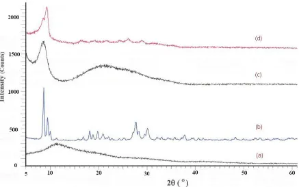
Figure 5. XRD pattern of: mesoporous (a) SiO2; (b) PVMo; (c) PVMo/ SiO2 (20%); and (d) PVMo/ SiO2
[image:6.596.84.521.433.706.2]
The Keggin category of the heteropolyanion was also proved by X-ray diffraction, which demonstrated typical peaks at 2θ: 8.8°, 9.2°, 10.3°, 27.9° and 29.2° [31]. Obviously, the obtained sample belonged to the set of Keggin-type heteropolyanions (Fig. 5). The XRD patterns of SiO2 bulk, PVMo
bulk and SiO2 containing 20 and 40 wt% of PVMo, are obtained in Fig. 5. No diffraction characteristic
peaks for PVMo appeared in the spectra of catalyst containing 20% polyoxoanion. This is an effect of finely discreted PVMo in the porous structure of silica, and the composite behaves as X-ray amorphous. The XRD model for material with 40% of PVMo illustrates all the characteristic peaks of the polyoxoanion, therefore demonstrating that part of the PVMo is extra, and structures large enough crystallites in the superior pores of silica and on its external surface to provide a diffraction pattern.
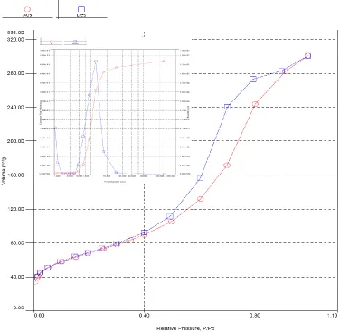
In Fig. 6, nitrogen sorption isotherm of PVMo/SiO2 has been exposed. All samples were
mesoporous, with N2 adsorption–desorption isotherms of kind IV according to the IUPAC
categorization [35, 36]. The BET surface area of the material is 210 m2 g−1. The values of P/P0 close to
[image:7.596.110.486.361.728.2]the inflection point are intimately connected to the pore-widths, which recline in the mesoporous range [37]. Pore size diameter of the sample anticipated employing the Barrett-Joyner-Halenda (BJH) technique is ca. 6.1 nm, which is in excellent accord with the pore widths predicted from the TEM image.
Figure 6. N2 adsorption–desorption isotherm of the PVMo/SiO2. Inset: Pore size distribution using BJH
In addition, the BET surface areas and pore diameter of the samples are also offered in Table 1. In evaluation with the porous silica, both the BET surface area and pore volume of the PVMo/ SiO2
[image:8.596.69.523.211.255.2]catalyst have been shortened due to the preface of PVMo on the silica. The above experimental results illustrated that PVMo have been supported on the surface of silica based on electrostatic communication and keeping its electrochemical properties.
Table 1. The Special surface area, pore size and pore volume.
Sample Specific surface Area (m2/ g) Pore size (nm) Total pore volume (cm3/g)
SiO2 179.86 83.4 0.367
PVMo/SiO2 210 64.7 0.901
[image:8.596.173.420.530.710.2]The electrochemistry of the [PMo (12-n) VnO40] (3+n)- species have been considered formerly
[37, 38]. The aim of this part is to evaluate the electrochemistry of the PMo10V2O405- (PVMo) and
SiO2-PMo10V2O405- (PVMo/ SiO2). The PVMo/ SiO2 are not soluble in any solvent. Therefore, the
electrochemical studies of PVMo and PVMo/ SiO2 were approved in aqueous solution using carbon
paste electrodes (CPEs) which were modified with PVMo and PVMo/ SiO2.
The mixture of 0.5 g PVMo/ SiO2, and 0.5 g graphite powder were mixed collectively. Then
diethyl ether was added and mixture was mixed to obtain homogeneous mixture. After evaporation of diethyl ether, 0.3 g paraffin oil was added and the mixture was mixed with mortar and pestle to obtain a consistently wetted paste. The prepared paste was inserted in to a glass tube (internal radius 2.2 mm). To get ready a blank solution, 10.0 ml of the buffer solution (phosphate buffer, 0.10 M, pH 7.0) was transferred into an electrochemical cell. The differential pulse voltammogram (DPV) was recorded with a pulse height of 50 mV and a pulse width of 5 mV and the potential scanned from +0.20 and +0.70 V vs. Ag/AgCl.
-60 -50 -40 -30 -20 -10 0 10 20 30 40 50
-0.7 -0.4 -0.1 0.2 0.5 0.8 1.1 1.4
Potential/V (vs. Ag/AgCl)
C
urrent/
µA a
b c
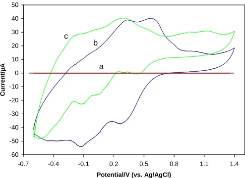
Figure 7. Cyclic voltammogram of: (a) bare CPE; (b) PVMo-CPE; and (c) PVMo/ SiO2 -CPE in 0.2M
Figure 7, confirms the cyclic voltammograms in 0.2 M H2SO4 aqueous solution at a naked CPE
(Fig. 7a), PVMo-CPE (Fig. 7b) and a PVMo/ SiO2-CPE (Fig. 7c). It could be seen in Fig. 7 that in the
potential variety of -0.6 to 1.4 V (vs. Ag/ AgCl), there is no redox peak at the naked CPE, while the voltammograms of PVMo-CPE and PVMo/ SiO2-CPE display some consecutive redox processes.
Comparing the voltammograms of PVMo and PVMo/ SiO2 illustrated that the immobilization of
negatively charged PVMo on the surface of silica, led to a negative shift of the peak potentials and a raise in the separation of the peak potentials, which are in concord with the previously reported consequences [36]. This happening can be attributed to the interaction between the negatively charged redox couple and the oppositely charged silica matrix.
3.2. Alkene epoxidation with H2O2 catalyzed by nanocomposite PVMo/ SiO2 under reflux and ultrasonic irradiation conditions
At first, the nanocomposite PVMo/ SiO2 with various catalyst loadings (PVMo) were arranged
and considered their catalytic activity in the epoxidation of cyclooctene as model reaction with H2O2.
The results proved that the nanocomposite catalyst with 20% loading of PVMo is more efficient (Table 2).
Table 2. Epoxidation of cyclooctene with H2O2 (30%) catalyzed by PVMo/ SiO2 with the diverse
catalyst loading.a
Entry Catalyst loading (wt %)
Epoxide yield after (5 h)
Epoxide yield after (10 h)
1 20 50 99
2 10 35 75
3 5 26 56
4 3.5 18 48
5 2.5 12 39
6 2 6 35
a
Reaction conditions: PVMo/ SiO2 (0.0475 mmol); olefin (1 mmol); H2O2 (1 mL); CH3CN (5 mL),
[image:9.596.58.543.617.733.2]temperature: 78 °C.
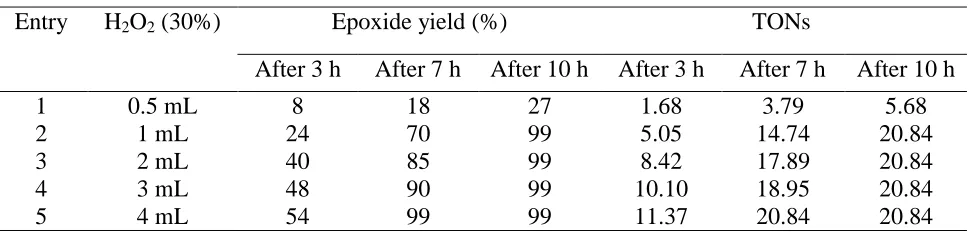
Table 3. Oxidant selectivity in the oxidation of cyclooctene catalyzedbyPVMo/ SiO2.a
Entry H2O2 (30%) Epoxide yield (%) TONs
After 3 h After 7 h After 10 h After 3 h After 7 h After 10 h
1 0.5 mL 8 18 27 1.68 3.79 5.68
2 1 mL 24 70 99 5.05 14.74 20.84
3 2 mL 40 85 99 8.42 17.89 20.84
4 3 mL 48 90 99 10.10 18.95 20.84
5 4 mL 54 99 99 11.37 20.84 20.84
a
Reaction conditions: PVMo/ SiO2 (0.0475 mmol); olefin (1 mmol); CH3CN (5 mL), temperature: 78 °
The epoxidation of cyclooctene was also examined with various amounts of 30% aqueous H2O2
to indicate the oxidant selectivity (Table 3). Therefore, the amount of 1 ml of 30% H2O2 was selected
as most favorable amount for oxidant. These studies are beforehand reported by Nomiya [37].
Besides, the results proved that no cyclooctene oxide was detected at room temperature. Thus, all reactions were carried out at 78 °C.
The ability of nanocomposite catalyst (PVMo/ SiO2) in the epoxidation of various linear, cyclic
and phenyl substituted alkenes as substrate with H2O2 was investigated. The results explain evidently
that the conversions, selectivity and TONs are upper for heterogeneous nanocomposite (PVMo/ SiO2)
[image:10.596.80.521.282.761.2]in comparison with the homogeneous PVMo (Tables 4).
Table 4. Alkene epoxidation with H2O2 catalyzed by PVMo and PVMo/ SiO2 nanocomposite beneath
magnetic stirring (MS) and under ultrasonic irradiation (US).a
Entry Substrate
Conversion (%)b Epoxide yield (%)b TOF(h-1)
P
VMo
c ti
me( h -1 ) P VMo/ S iO 2 (M S ) c / ti me (h -1 ) P VMo/ S iO 2 (U S )
c ti
me( mi n ( P VMo P VMo/ S iO 2 (M S ( P VMo/ S iO 2 (U S ) P VMo P VMo/ S iO 2 (M S ) P VMo/ S iO 2 (U S )
1 100 100 95 95 98 90 1.1 1.1 40
2 85 97 88 70 92 82 0.89 1.02 37.1
3 95 98 92 73 95 85 1.0 1.03 38.7
4 49 85 90 43 78 75 0.51 0.89 37.9
5 29 98 93 27 92 70 0.31 1.03 39.2
6 28 48 65 20 42 60 0.29 0.51 27.4
7 59 68 83 56 65 68 0.62 0.72 34.9
8
a
Reaction condition: PVMo/ SiO2 (0.0475 mmol); alkene (1 mmol); H2O2 (1 mL); CH3CN (5 mL),
temperature: 78 °C.
b
GC yield.
c
The reaction time is 20 h for reflux conditions and 30 min for ultrasonic conditions.
The most advantageous conditions which were utilized for alkene epoxidation under ultrasonic irradiation are as what expressed for alkene epoxidation under agitation with magnetic stirring. The reaction mixture was irradiated by ultrasonic waves. The obtained results illustrated that in this catalytic system, the reaction times are shorter and the TONs are higher than mechanical stirring and reflux conditions (Table 4). In the case of α-pinene, the epoxide yield was enlarged to 60%.The catalytic activity of PVMo/ SiO2 rose in the epoxidation of linear alkenes such as octene and
1-dodecene, and in the case of norbornene. In contrast with the data obtained under agitation with magnetic stirring, the reaction times are shorter, product yields are higher, and in some case the selectivity enhance.
0 10 20 30 40 50 60 70 80 90 100
20 40 60 80 100
Ultrasound Intensity
Ep
o
x
id
e
Yi
e
ld
(%
)
Figure 8. The effect of ultrasonic irradiation intensity on the epoxidation of cyclooctene with H2O2
catalyzed by PVMo/ SiO2
[image:11.596.185.412.349.494.2] [image:11.596.188.403.562.728.2]
The effect of irradiation intensity on the epoxidation of cyclooctene was also investigated; in which the higher epoxide yield was observed at 100% intensity (Fig. 8).
Fig. 9 shows a comparison between systems under ultrasonic irradiation and under agitation with magnetic stirring, which shows the effect of ultrasonic irradiation on the catalytic activity.
As exposed formerly, peroxo radical are generated within the pores at the PVMo sites (Scheme 2). The following oxidation of the hydrocarbon can occur both inside the pores and in the bulk liquid solution [38, 39]. Ultrasonic irradiation encourages the generation of radicals in the reaction media and this can go faster the reaction. Conversely, the collapse of the created bubbles results in production of high temperatures. As the reaction under mechanical stirring requires the temperature about 80 °C, Consequently, the reaction can be also increase speed under ultrasonic irradiation.
VV H
2O2
VV H
2O2
VV + H 2O2
VIV + HOO + H
.
+Scheme 2.
[image:12.596.196.441.263.328.2]3.3. Catalyst reuse and stability
Table 5. Epoxidation of cyclooctene with H2O2 (30%) catalyzed by PVMo/ SiO2 recycled under reflux
conditions and under ultrasonic irradiation.a
Entry Reflux conditions Ultrasonic irradiation
Time (h)
Conversion (%)
Epoxide yield (%)
Catalyst leached
(%)
Time (min)
Conversion (%)
Epoxide yield
(%)
Catalyst leached (%)
1 10 100 98 3 40 98 > 98 2
2 10 85 83 1 40 90 87 1
3 10 80 78 1 40 85 83 1
4 10 75 73 1 40 80 77 1
a
Reaction condition: PVMo/ SiO2 (0.0475 mmol); olefin (1 mmol); H2O2 (1 mL); CH3CN (5 mL).
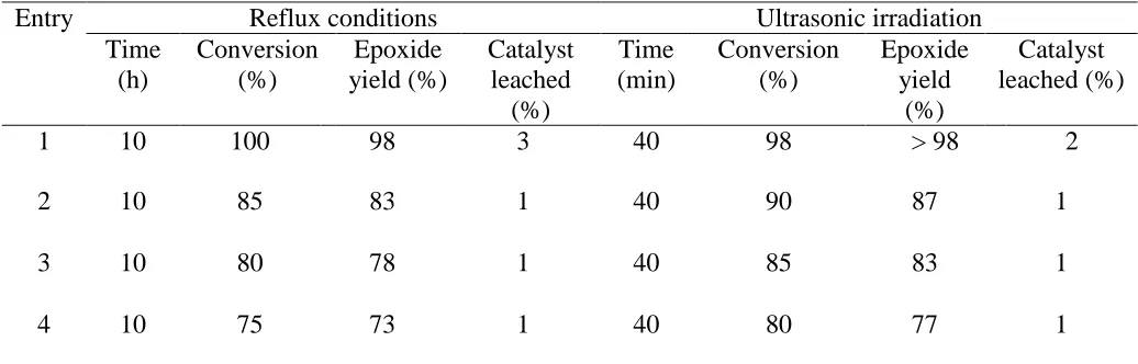
The constancy of the nanocomposite PVMo/ SiO2 was monitored using multiple in order
epoxidation reactions both under agitation with magnetic stirring and ultrasonic irradiation. For each of the repeated reactions the catalyst was recovered by simple filtration, washed thoroughly with water, methanol, acetonitrile and 1, 2-dichloroethane, consecutively, and dried before being used.
[image:12.596.39.557.446.612.2]
The amount the catalyst, which was leached each run was determined by inductively coupled plasma (ICP) Analysis. The consequences are exposed in Table 5. The nature of recovered catalyst has been followed by IR. The results indicated that the catalyst after recovering several times, demonstrated no significant alter in its IR spectrum.
In table 6. The activity of the supported catalyst with other reported catalysts for the epoxidation of cyclooctene with H2O2 (30%) catalyzed and other reported methods under magnetic
[image:13.596.62.535.291.621.2]stirring (MS) and under ultrasonic irradiation (US) were comprised. The conversion amounts in this method have been the best.
Table 6. Comparison of reaction data for the present system in epoxidation of cyclooctene and other reported methods under magnetic stirring (MS) and under ultrasonic irradiation (US) in almost conditions .a
E
n
tr
y
Substrate Conversion (%)
b Epoxide yield (%)b Ref
P
VMo
c ti
m e(h -1 ) (M S ) c / ti m e(h -1 ) (US)
c tim
e( m in ( PVMo (MS ( (US)
1 PVMo/ SiO2 100 100 95 95 98 90 This paper
2 PVMo/ CNTs 78 80 95 96 100 100 [19]
3 PVMo /MMT 55 58 71 96 65 77 [17,23]
4 PVMo/ PANI 52 62 90 90 89 98 [20]
5 PVMo/ ZrO2 55 70 93 95 80 97 [21]
6 PVMo/ TiO2 78 85 98 96 100 100 [22]
a
Reaction condition: PVMo/ SiO2 (0.0475 mmol); alkene (1 mmol); H2O2 (1 mL); CH3CN (5 mL) b
GC yield.
c
The reaction time is 20 h for reflux conditions and 30 min for ultrasonic conditions.
4. CONCLUSIONS
We productively produced the PVMo/ SiO2 nanocomposite by straightforward impregnation
alkenes than parent heteropolymolybdate (PVMo). The use of ultrasonic irradiation enhanced the conversion and decreased the reaction times. The consequences explained that excellent catalytic activity of the heteropolymolybdate; particularly under ultrasonic irradiation make them valuable catalysts for extra applications in the region of catalysis. Moreover, the H2O2 is a green and
eco-friendly oxidant in these arrangements. The performed search on the electrochemical presentation of the dissolved heteropolymolybdate distinguishes it as an outstanding electroactive for the H2O2
reduction. The polyoxoanion, immobilized in a mesoporous silica matrix, qualitatively retained its electrochemical behavior displayed in solution, but for both the immobilization matrix the electrocatalytic effectiveness and the sensitivity toward H2O2 reduction were superior.
ACKNOWLEDGEMENTS
The support of this work by Catalysis Division of University of Payame Noor University (PNU) and Chemistry department of Isfahan University (CECUI) is acknowledged.
References
1. J. Zhang, L. Xu, Y.Cui, W. Cao, Z. Li, Mat. Chem. Phy 90 (2005) 47-52. 2. H. Jong Kim, Y.Gun Shul, H. Han, Appl. Catal. A: Gen 299 (2006) 46-51.
3. S. Damyanova, L. Dimitrov, R. Mariscal, J.L.G. Fierro, L. Petrov, I. Sobrados, Appl. Catal. A: Gen 256 (2003) 183-197.
4. L. Zhang, Q. Jin, L. Shan, Y. Liu, X. Wang, J. Huang, Appl. Clay Sci. 47 (2010) 229-234. 5. I. V. Kozhevnikov, J. Mol. Catal. A: Chem. 262 (2007) 86-92.
6. Y. Tang, J. Zhang, Trans. Met. Chem, 31 (2006) 299-305.
7. Y.L. Shi, W.Qiu, J.Zhang, J. Phys. Chem. Solids. 67 (2006) 2409-2418. 8. T. Okuhara, N. Mizuno, M. Misono, Adv. Cata. 41 (1996) 113-252.
9. M.Misono, I. Ono, G. Koyano, A. Aoshima, Pure. Appl. Chem. 72 (2000) 1305–1311. 10. K. Nowinska, R. Fiedorow, J. Adamiec, J. Chem. Soc., Faraday Trans. 87 (1991) 749-753. 11. W.C. Cheng, N. P. Luthra, J. Catal. 109 (1988) 163-169.
12. K. M. Rao, R. Gobetto, A. Iannibello, A. Zecchina, J. Catal. 119 (1989) 512-516. 13. H.J. Kim, Y.G. Shul, H. Han, Appl.Catal. A:Gen 299 (2006)46–51.
14. L. R. Pizzio, C. V. Cáceres, M. N. Blanco, Appl. Catal., A Gen. 167 (1998) 283-294. 15. D. Kumar, C. C. Landry, Micropor. Mesopor. Mat. 98 (2007)309–316.
16. B.M. Devassy, F. Lefebvre, W. Böhringer, J. Fletcher, S.B. Halligudi, J.Mol.Catal A: Chem 236 (2005) 162–167.
17. H. Salavati, S. Tangestaninejad, M. Moghadam, V. Mirkhani, I. Mohammadpoor-Baltork, Ultrason. Sonochem 17 (2010) 145–152.
18. H. Salavati, N. Rasouli, Mater. Res. Bull. 46 (2011) 1853–1859.
19. H. Salavati, S. Tangestaninejad, M. Moghadam, V. Mirkhani, I. Mohammadpoor-Baltork, Ultrason. Sonochem 17 (2010) 453–459.
20. S. Tangestaninejad, M. Moghadam, V. Mirkhani, I. Mohammadpoor-Baltork, E.Shams, H. Salavati, Catal.Commu 9 (2008) 1001–1009.
21. H. Salavati, S. Tangestaninejad, M. Moghadam, V. Mirkhani, I. Mohammadpoor-Baltork, Comptes. Rendus. Chimie. 14 (2011) 588–596.
22. H. Salavati, N. Rasouli, Appl.sur.sci. 257 (2011) 4532–4538.
24. L R. Pizzio, C. V. Cáceres, M. N. Blanco, J. Coll. Interf. Sci. 190 (1997)318-326. 25. T. Baba, Y. Ono, Appl Catal 22 (1986) 321-324.
26. S. Gaspar, L. Muresan, A. Patrut, I. C. Popescu, Anal. Chim. Acta,385 (1999) 111-117. 27. A. Teimouri, A. Najafi Chermahini, J. Mol. Catal A: Chem. 346 (2011) 39-45.
28. A. Teimouri, A. Najafi Chermahini, H. Salavati, L. Ghorbanian, J. Mol. Catal A: Chem. 373 (2013) 38-45.
29. Y. Izumi, K. Hisano, T. Hida, Appl. Catal. A: Gen 181 (1999) 277-282.
30. J. Toufaily, M. Soulard, J.-L. Guth, J. Patarin, L. Delmote, T. Hamieh, M. Kodeih, D. Naoufal, H. Hamad, Collo. Surf. A: Physicochem. Eng. Aspects 316 (2008) 285-291.
31. L. Pettersson, I. Andersson, A. Selling, G. H. Grate, Inorg. Chem. 33 (1994) 982-993. 32. P. Stati, S. Freni, S. Hocevar, J. Power Sources 79 (1999) 250-255.
33. M. A. Hamon, H. Hu, P. Bhowmik, S. Niyogi, B. Zhao, M. E. Itkis, R. C. Haddon, Chem. Phys. Lett. 347 (2001) 8-12.
34. N. K. Kala Raj, A. V. Ramaswamy, P. Manikandan, J. Mol. Catal A: Chem. 227 (2005) 37-45. 35. K. S. W. Sing; D. H. Everett, R. A. W. Haul, L. Moscou; R. A. Pierotti; J. Rouquerol; T.
Siemieniewska, Pure & Appl. Chem 57(4) (1985) 603-619.
36. D. Chandra, B.K. Jena, C.R. Raj, A. Bhaumik, Chemistry of Materials 19 (2007) 6290–6296. 37. K. Nomiya, K. Yagishita,Y. Nemoto, T. A. Kamataki, J. Mol. Catal. 126 (1997) 43.
38. B. R. Limonges, R. J. Stains, J. A. Turner, A. M. Herring, Electrochim. Acta 50 (2005) 1169-1179. 39. Y.T. Chang, K.C. Lin, S.M. Chen, Electrochim. Acta 51 (2005) 450-461.
40. S. Inagaki, Y. Fukushima, K. Kuroda, Journal of the Chemical Society, Chem. Commun (1993) 680–681.
41. S. Gaspar, L. Muresan, A. Patrut, I. C. Popescu, Anal. Chim. Acta 385 (1999) 111-117. 42. H. Salavati, H. Saedi, Int. J. Electrochem. Sci., 10 (2015)4208 – 4222.
43. K. Nomiya, S. Matsuoka, T. Hesegawa, Y. J. Nemoto. J. Mol. Catal A: Chem 156 (2000) 143-152. 44. A. M. Khenkin, R. Neumann, A. B. Sorokin, A. Tuel, Catal. Lett. 63 (1999) 189-192.
45. C. Shi, R. Wang, G. Zhu, S. Qiu, J. Long, Eur. J. Inorg. Chem (2005) 4801-4807.