Catterson, V.M. and Davidson, E.M. and McArthur, S.D.J. (2005) Issues in
integrating existing multi-agent systems for power engineering
applications. In: 13th International Conference on Intelligent Systems
Application to Power System (ISAP), 2005-11-06 - 2005-11-10, Arlington,
USA. ,
This version is available at
https://strathprints.strath.ac.uk/26528/
Strathprints is designed to allow users to access the research output of the University of Strathclyde. Unless otherwise explicitly stated on the manuscript, Copyright © and Moral Rights for the papers on this site are retained by the individual authors and/or other copyright owners. Please check the manuscript for details of any other licences that may have been applied. You may not engage in further distribution of the material for any profitmaking activities or any commercial gain. You may freely distribute both the url (https://strathprints.strath.ac.uk/) and the content of this paper for research or private study, educational, or not-for-profit purposes without prior permission or charge.
Any correspondence concerning this service should be sent to the Strathprints administrator:
The Strathprints institutional repository (https://strathprints.strath.ac.uk) is a digital archive of University of Strathclyde research outputs. It has been developed to disseminate open access research outputs, expose data about those outputs, and enable the
Intelligent Systems Application to Power System (ISAP), 6-10 November 2005, Arlington, USA.
http://strathprints.strath.ac.uk/
26528
/
Strathprints is designed to allow users to access the research output of the University of
Strathclyde. Copyright © and Moral Rights for the papers on this site are retained by the
individual authors and/or other copyright owners. You may not engage in further
distribution of the material for any profitmaking activities or any commercial gain. You
may freely distribute both the url (
http://strathprints.strath.ac.uk
) and the content of this
paper for research or study, educational, or not-for-profit purposes without prior
permission or charge. You may freely distribute the url (
http://strathprints.strath.ac.uk
)
of the Strathprints website.
1
AbstractÑ Multi-agent systems (MAS) have proven to be an effective platform for diagnostic and condition monitoring applications in the power industry. For example, a multi-agent system architecture, entitled Condition Monitoring Multi-agent System (COMMAS)[1], has been applied to the ultra high frequency (UHF) monitoring of partial discharge activity inside transformers. Additionally, a multi-agent system, entitled Protection Engineering Diagnostic Agents (PEDA)[2], has demonstrated the use of MAS technology for automated and enhanced post-fault analysis of power systems disturbances based on SCADA and digital fault recorder (DFR) data.
In this paper the authors propose the integration of COMMAS and PEDA as a means of offering enhanced decision support to engineers tasked with managing transformer assets. By providing automatically interpreted data related to condition monitoring and power system disturbances, the proposed integrated system will offer engineers a more comprehensive picture of the health of a given transformer. Defects and deterioration in performance can be correlated with the operating conditions it experiences.
The integration of COMMAS and PEDA has highlighted the issues inherent to the inter-operation of existing multi-agent systems and, in particular, the issues surrounding the use of differing ontologies. The authors believe that these issues will need to be addressed if there is to be widespread deployment of MAS technology within the power industry. This paper presents research undertaken to integrate the two MAS and to deal with ontology issues.
Index TermsÑ Condition monitoring, Post-fault analysis, Multi-agent systems, Intelligent systems, Transformers.
I. INTRODUCTION
arious techniques, such as ultra high frequency (UHF) signal detection [3], acoustic emissions detection [4] and dissolved gas analysis [4], have been proposed as means of monitoring partial discharge activity within transformers. All of the above rely on sensors gathering data that can be used to identify the occurrence of unusual activity within the transformer. Unfortunately, as is the case with many types of power system data, meaningful information on plant health is implicit: interpretation of the data is required. In addition, the volume of the data often makes manual analysis of the data by an expert impractical.
Through earlier research, a layered multi-agent system architecture for automating the analysis of condition monitoring data was developed [1]. Applied to the monitoring of partial discharge activity in transformers, the Condition Monitoring Multi-agent System (COMMAS) encapsulates
different classification techniques as separate agents and automatically diagnoses defects within a transformer through collaboration and corroboration. While the flexibility of the COMMAS architecture allows other condition monitoring data sources to be added, currently COMMAS derives its diagnosis using only the UHF monitoring data.
SCADA and Digital fault recorder (DFR) data offer a perspective on the network conditions experienced by a transformer. The operation of plant specific unit protection, e.g. Buchholz protection or other transformer protection, can be quickly ascertained from SCADA data. Network disturbances in the vicinity of the transformer can also be identified through the interpretation of SCADA. If a digital fault recorder is installed in a transformerÕs substation, then DFR data can be used to build a profile of the transients, such as fault currents and over-voltages, experienced by the transformer. This profile, in addition to an assessment of transformer health using interpreted condition monitoring data, may be used to inform maintenance decisions. Moreover, knowledge of the occurrence of disturbances, switching operations and other activity on the power system, may impact on the analysis of the condition monitoring data itself by offering additional information that can be used to help discriminate between competing diagnoses.
The desire to explore the use additional data sources to enhance condition monitoring has led the authors to investigate the integration of COMMAS with another existing multi-agent system called Protection Engineering Diagnostic Agents (PEDA) [2]. The PEDA system integrates a number of intelligent systems in order to automate post-fault analysis using SCADA and DFR data. Using PEDA, engineers can quickly access interpreted SCADA and DFR data relating to specific circuits, substations or items of plant. Combining the functionality of PEDA with the functionality of COMMAS provides engineers with decision support based on condition monitoring data, SCADA and DFR data.
In this paper the authors focus on the issues inherent to the integration of existing multi-agent systems and propose how the integration can be achieved for the case of COMMAS and PEDA. The paper commences with a brief description of both multi-agent systems. The areas where information derived by PEDA may enhance the functionality of COMMAS are also discussed. The paper then focuses on the integration of the two systems and, more specifically, the effect of the ontology on the interoperation of multi-agent systems. This is a critical issue for the future adoption of multi-agent technology within the power industry. As more researchers use MAS for advanced functions, there will be an increasing requirement for data and information exchange between such systems. To
Issues in Integrating Existing Multi-agent
Systems for Power Engineering Applications
Victoria M. Catterson, Euan M. Davidson, Stephen D. J. McArthur, Member, IEEE
V
Manuscript received April 1st, 2005. This work was supported in part by SP Power Systems plc. and the Engineering and Physical Sciences Research Council UK.
These must encompass the ontology issues raised and discussed in this paper.
[image:4.612.45.301.119.366.2]II. COMMAS
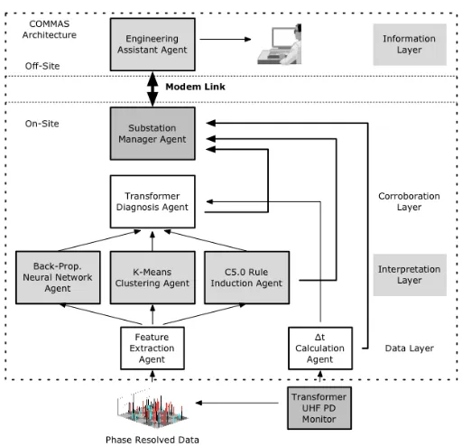
Figure 1: The COMMAS Architecture
The COMMAS architecture (figure 1) is structured to follow the refinement of raw condition monitoring data into high-level condition assessment information. The analysis process is split into four stages, represented here as layers of the system. These are the data monitoring layer, the interpretation layer, the corroboration layer, and the information layer. Each layer contains one or more agents that provide COMMAS with the required data processing and interpretation functionality.
At the data monitoring layer, signals from sensors are captured and processed to extract particular features of interest by the feature extraction agent.
The interpretation layer employs multiple techniques for fault diagnosis based on the features derived by the feature extraction agent. Agents that implement K-Means clustering, C5.0 rule induction, and a back-propagation neural network [5], all attempt to classify partial discharge activity using the particular technique they embody.
The strength of the COMMAS system comes from the corroboration layer; the transformer diagnosis agent receives the various fault diagnoses generated by each of the agents at the interpretation layer and, by corroborating the diagnoses, makes a decision about the most likely source of any partial discharge activity inside the transformer. Detailed discussion of the function and interaction of the individual agents and the corroboration process can be found in [1] and [6] respectively. The corroborated diagnosis is provided, along with a confidence factor, to agents at the information layer.
Engineers can access the interpreted condition monitoring
information layer. The EAA acts as a graphical user interface (GUI) and presents condition assessment. This can run off-site from the substation, wherever condition information is needed. However, if there is no information layer currently running, the substation manager agent archives the data on-site until a user connects and requests it.
The EAA automatically updates defect diagnosis information as it becomes available; but the engineer can also request more low-level data, such as raw sensor data, to confirm the systemÕs conclusions. The EAA can be used to monitor multiple transformers across many substations, making it a convenient tool for integrating many data sources.
III. PROTECTION ENGINEERING DIAGNOSTIC AGENTS
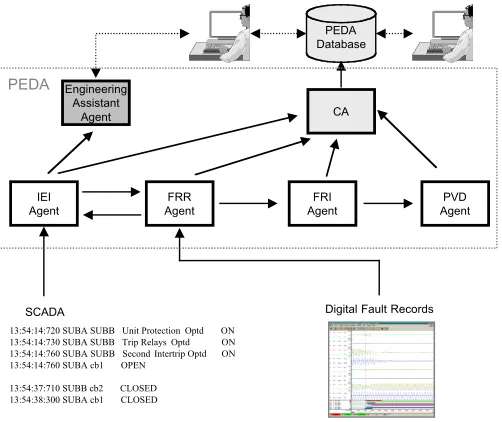
PEDA (figure 2) employs multi-agent system technology to integrate a number of disparate legacy intelligent systems and data retrieval systems in order to automatically collate and analyze power system data relating, primarily, to protection operation. Detailed examination of the PEDA agent interactions and the underlying techniques they employ can be found in [2][8]. The system comprises the following agents:
¥ An Incident and Event Identification (IEI) Agent:
this agent ÔwrapsÕ a rule-based expert system that identifies power system incidents, such as disturbances and switching operations, from ÔliveÕ SCADA data. When an incident occurs the IEI agent uses the expert system to identify the relevant alarms, classify the type of incident and assess some aspects of protection operation.
¥ A Fault Record Retrieval (FRR) Agent: the FRR agent connects to the utilityÕs fault record database and makes new records available to other agents.
¥ A Fault Record Interpretation (FRI) Agent: the FRI agent ÔwrapsÕ a rule-based expert system for classifying and interpreting DFR data.
¥ A Protection Validation and Diagnosis (PVD)Agent: the PVD agent ÔwrapsÕ a model-based reasoning engine that employs models of the protection system to validation protection performance [7].
¥ A Collation Agent (CA): The collation agent (CA) gathers information from the agents above and archives it in a database accessible via an intranet site. This intranet site gives engineers access to the latest information provided by the PEDA agents and also allows them to explore historical data for particular circuits as well as download and view fault records on their local desktop PC.
¥ Engineering Assistant Agents (EAA): Like COMMAS, PEDA also uses engineering assistant agents to provide tailored post-fault analysis information to engineers. Ultimately, PEDA offers the protection engineer a list of power systems incidents derived from SCADA data, along with the interpreted DFR data and model-based analysis of any protection operation for each of the incidents.
3 IEI Agent FRR Agent FRI Agent PVD Agent CA Engineering Assistant Agent PEDA Database
SCADA Digital Fault Records
13:54:14:720 SUBA SUBB Unit Protection Optd ON 13:54:14:730 SUBA SUBB Trip Relays Optd ON 13:54:14:760 SUBA SUBB Second Intertrip Optd ON 13:54:14:760 SUBA cb1 OPEN
[image:5.612.322.552.55.145.2]13:54:37:710 SUBB cb2 CLOSED 13:54:38:300 SUBA cb1 CLOSED PEDA
Figure 2: The PEDA multi-agent system
IV. ENHANCED DECISION SUPPORT THROUGH INTEGRATION
Utilizing a variety of data sources can burden engineers with the laborious task of collating data from different data gathering and retrieval systems in addition to the manual interpretation of the data. This detracts from their true focus: making asset management and operational decisions based on the information implicit in the monitoring data. The integration of COMMAS with PEDA provides engineers enhanced decision support by offering automatic collation, interpretation and corroboration of SCADA, DFR and condition monitoring data related to specific items of plant.
For example, consider a transformer supplying a circuit that historically experiences a large number of disturbances due to geography and weather. Condition monitoring apparatus applied to the transformer collects UHF data, which COMMAS analyzes using various techniques to detect partial discharges, and produces diagnoses based on three different techniques (Section 2). As is the case in many utilities, fault recorders are used to capture data relating to disturbances experienced by the transformer.
The integration of COMMAS and PEDA allows the engineer to configure his/her engineering assistant agent to subscribe to PEDA agents for interpreted data relating to the transformer (figure 3). In the case of a protection operation or an incident on the circuit, the IEI agent immediately sends details of its analysis to the engineerÕs EEA. Similarly the EEA can also be configured to subscribe to information from the FRR and FRI agents. When a fault record has captured data relating to the transformer, the FRR agent informs the EAA. The FRI agent also informs the EAA of the results of its analysis.
As a result, the EAA informs the engineer of activity on the transformer as soon as it occurs. The FRI agent supplies the engineer with details from the fault record, such as peak and average current, as well as the type and duration of the disturbance. The engineer can also download the fault record and examine the analogue voltage and current traces for
IEI Agent FRR Agent FRI Agent Transformer Diagnosis Agent Engineering Assistant Agent PEDA COMMAS Subscribe Subscribe Subscribe Inform Inform Inform
Figure 3: The COMMAS Engineering assistant agent subscribes for interpreted data relating a particular transformer.
[image:5.612.50.301.60.271.2]IEI Agent FRR Agent FRI Agent Transformer Diagnosis Agent Engineering Assistant Agent PEDA COMMAS Subscribe Inform Inform Query-ref
Figure 4: PEDAÕs IEI Agent can inform COMMASÕs Transformer Diagnosis Agent of network activity.
particular incidents. The EAA logs this data along with the condition monitoring data, allowing the engineer to build a record of the transformerÕs health and the incidence of transients it experiences.
The integration of PEDA and COMMAS offers more than improved data gathering functionality. COMMASÕ transformer diagnosis agent can either subscribe to the PEDAÕs IEI agent, to be informed of activity in the substation or, when performing a diagnosis, query the IEI agent about the occurrence of any network activity at that time (figure 4). Knowledge of network activity can help discriminate between competing diagnoses, and thus improve the diagnostic capability of the COMMAS corroboration layer.
The technical aspects of integrating the two multi-agent systems; in particular, the issue of dealing with differing ontologies; required specific research activities which are discussed in the following sections.
V. INTER-AGENT COMMUNICATION ACROSS MULTI-AGENT
SYSTEMS
A. Background
Utilities are striving for increased integration between previously separate systems [9]. Recent standards such as CIM [10], which promote open interfaces between energy management systems from different vendors, can be seen as a case in point.
The integration of PEDA and COMMAS is predicated on the interoperability of agents: interoperability is a much cited and attractive feature of MAS technology, however, there has been little or no work published on the interoperation of existing multi-agent systems in power engineering, primarily because most MAS have yet to leave the laboratory.
[image:5.612.322.552.168.267.2]problem of merging data from independently developed systems will become more and more pressing. For example, projects such as SPIDS [11] and Wu et alÕs e-automation project [12] contribute other valuable power systems analysis information, which could be used to support or draw corroborating data from other systems.
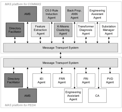
Figure 5: Integration of COMMAS and PEDA platforms
B. Standards for Multi-Agent Systems Interoperability
In recent years the Foundation for Intelligent Physical Agents (FIPA) standards have become the de facto standard for agent development within the computer science community. FIPA develops and promotes standards that afford interoperability between agents and multi-agent systems. These include a standard agent communication language (FIPA-ACL) [13], standard communicative acts [14]; standard content languages [15], standard message transport protocols [16] and a standard that proscribes the agents that a MAS must implement to be FIPA compliant [16]. Using these standards, multi-agent systems developed using different platforms should be able to interoperate.
As PEDA and COMMAS were implemented using an agent development environment [17] that supports many of the FIPA standards above, it is a relatively trivial step to connect the two platforms together (figure 5). The systems utilize a common ACL ACL), content language (FIPA-SL), and a standard message transport protocol (HTTP), which allows the agents to communicate with each other across a network, and register and search for services using each platformÕs directory facilitator (DF) and agent management service (AMS) agents.
However, this does not mean that the agents can share any useful information: although they employ the same ACL and content language, the agents use different ontologies. While ACL offers a framework for standardized inter-agent communication, the standard only defines the type and structure of messages and the interaction protocols, i.e. the flow of messages, for each conversation, expected by the agents. In other words, the agents speak the same language but do not share a common vocabulary.
In an ACL message, the message content is delivered as one particular field of the message. This must be understood by an agent for the message to make sense: this requires that the structure and meaning of the content is in a format expected by the receiving agent, so it can decode the senderÕs intentions.
The content of a message comprises two parts: content language and ontology. A content language provides the syntax, or grammar, of the content. The semantics, or lexicon, of a message is drawn from an ontology. FIPA has proposed standards for four content languages, with different purposes in mind. These are the FIPA Semantic Language (FIPA-SL); Knowledge Interchange Format (KIF); Resource Description Framework (RDF); and Constraint Choice Language (CCL). Non-FIPA standards for specifying content, such as Description Logic [18], also exist.
Both PEDA and COMMAS use FIPA-SL as the content language, simply because it is the only one of the four that has reached a stable standard; KIF, RDF, and CCL are all still experimental, whereas FIPA-SL was released as a standard in 2002. Experimental standards are liable to change, a problem encountered during the development of PEDA with the experimental version of FIPA-SL [8].
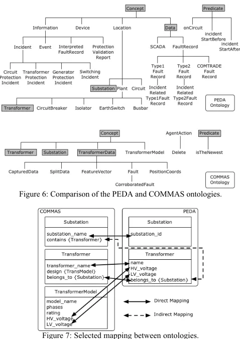
The content language chosen will shape the ontology. In the case of FIPA-SL, an ontology comprises a list of concepts, predicates, and actions specific to the domain of communication. Concepts, as the name suggests, model domain concepts, e.g. substations, transformers and feature vectors in COMMASÕ ontology (figure 6). Predicates specify concept relationships, and can always be evaluated as true or false. An example predicate for PEDAÕs ontology would be:
onCircuit(Circuit, Incident).
This is used to discuss whether an incident occurred on a particular circuit. An action is a special type of concept specifically for communicative acts such as request and call-for-proposal, where agents discuss an event happening. An action from the COMMAS ontology is:
Delete(TransformerData).
This action allows agents to discuss the deletion of particular facts from their local data stores. The requirement for particular subclasses of these three will change depending on the communication models employed in a system.
D. Differing Ontology and Ontology Mapping
Since COMMAS and PEDA were both designed for the power system domain, it is to be expected that there is some overlap between each ontology. Indeed, if there were no common terms, it would be unlikely that communication between the systems would be possible or useful.
5
Transformers. In the PEDA Ontology, a Substation includes a
substation_id field only. Plant items may be associated with a Substation, but there is no need for a reciprocal association in PEDA. The substation_name and substation_id fields are equivalent, despite slightly different names.
This does not indicate an incorrect ontology development process for either system; it simply reflects the different focus of each application. The fundamental concepts of the power systems domain are common, but the particular aspects of these concepts required by PEDA and COMMAS differ. This leads to the conclusion that a mapping exists between the two ontologies, but translating messages from one to another is not a simple case of transliteration.
E. Ontologies and MAS integration
The use of different ontologies presents a problem when an agent has to reason about related information it has received in messages expressed using differing ontologies. For example, consider the interactions in figure 3. The engineering assistant agent receives messages from COMMASÕ transformer diagnosis agent and from PEDAÕs data analysis agents. The agent has to resolve the equivalent information it is receiving about the transformer. To do this, the EAA needs knowledge of the mapping between the ontologies. This is not only a problem for integrating PEDA and COMMAS, but for integrating MAS in general. Possible solutions to this problem are discussed in the following sections.
[image:7.612.53.292.378.716.2]Figure 6: Comparison of the PEDA and COMMAS ontologies.
Figure 7: Selected mapping between ontologies.
VI. DEALING WITH DIFFERING ONTOLOGIES
A. The FIPA Ontology Service
FIPAÕs solution to the problem of using multiple ontologies comes in the form of an Ontology Agent that provides a number of ontology-related services [19]. The list of possible services is given as:
1. Locating and accessing public ontologies; 2. Maintaining a list of public ontologies; 3. Translating expressions between ontologies; 4 . Providing information about the relationship
between two terms or ontologies;
5. Identifying an ontology common to two agents. There are a number of issues with implementing this solution, not least of which is that the relevant FIPA standard is still experimental. Part of the problem may be that the state of the art in ontology mapping [20] falls short of what is required to automate services 3,4 and 5 above.
In the main, mappings between ontologies have to be hand crafted by the ontologiesÕ designers. In the case of COMMAS and PEDA, the designers had to identify parts of the ontologies which were semantically similar but syntactically different. Through discussions held over a number of meetings, the designers came to agreement on the relationship between terms (figure 6). This process must be followed for every pair of ontologies, as intermediary ontology translations would introduce more complexity and room for error. This leads to an exponentially increasing number of translation mappings as the number of ontologies increases. As the situation currently stands, most researchers developing MAS solutions to different domain problems are developing their own ontologies. For the sake of argument, consider the integration of 4 existing multi-agent systems. This would require 6 ontology mappings to be defined. This is likely to involve a large amount of human effort at the time of system integration, and thus influence the cost of implementing agent-based solutions to power engineering problems.
B. An Upper Ontology for Power Engineering Condition Monitoring
In the case of COMMAS and PEDA, the authors have merged the ontologies by finding and resolving the common concepts, as in figure 7, to form a new ontology for condition monitoring and disturbance diagnosis. The use of a single ontology means that agents from both systems can communicate without ambiguity. This allows the authors to integrate the two systems to explore the effect of power system event knowledge on condition monitoring.
Engineering
The original ontologies developed for COMMAS and PEDA, which are domain problem specific, are lower ontologies. Despite this, the shared concepts between the original ontologies are not domain problem specific, and hence can be identified as general upper ontology concepts. These are the concepts that require mapping between the two systems, so a common upper ontology would remove this need.
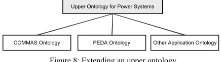
If an upper ontology for power engineering was developed, it could serve as an open standard that would aid the development of MAS solutions. The upper ontology would not act as a standard ontology for all applications; MAS developers would extend the upper ontology in order to form the problem specific lower ontology required for their application.
Upper Ontology for Power Systems
[image:8.612.62.280.258.320.2]COMMAS Ontology PEDA Ontology Other Application Ontology
Figure 8: Extending an upper ontology
This does not eliminate the problem of ontology mapping, but it may reduce the size of the task. Developers would not find themselves having to deal with many different models of common concepts, such as those common to the PEDA and COMMAS ontologies, and the domain specific concepts will not often need to be translated between systems. An upper ontology would also serve as a starting point for those developing their own domain problem specific ontologies, reducing development costs of MAS in the first place.
However, no upper ontology for power engineering is currently freely available. The power systems Common Information Model (CIM) [10] may serve as a foundation for an upper ontology, as it is currently being explored as an open standard for data exchange. Additionally, work has been done on ontologies for particular applications [21][22], which may also provide a starting point for a more general power engineering ontology.
The issue of how to decide on an upper ontology for power industry MAS is one requiring a solution supported by the whole community. As interoperability is the desired outcome, any decision taken in isolation will be an unscalable temporary fix at best, like the current integration of COMMAS and PEDA. If the deployment of MAS for power engineering problems is to be widespread, this fundamental question must be answered to the satisfaction of the community at large.
VII. CONCLUSIONS
By using the integration of two existing multi-agent systems as an example, this paper has explored some of the issues surrounding the interoperability of multi-agent systems. While open standards, such as those proposed by FIPA, lay foundations for the interoperability of different systems, the
unanswered.
The authorsÕ research has shown that an upper ontology can be produced for the condition monitoring field. Further research is required by the agent research community, in co-ordination with power engineers, to define an appropriate upper ontology for all power engineering applications.
VIII. REFERENCES
[1] S. D. J. McArthur, S. M. Strachan, G. Jahn. ÒThe Design of a Multi-Agent Transformer Condition Monitoring System,Ó IEEE Transactions on Power Systems, Vol. 19, No. 4, pp. 1845-1852, November 2004. [2] J.A. Hossack, J. Menal, S.D.J. McArthur, J.R. McDonald, ÒA
Multi-Agent Architecture for Protection Engineering Diagnostic AssistanceÓ,
IEEE Trans. on Power Systems, 2003.
[3] M. D. Judd, S. D. J. McArthur, J. R. McDonald, O. Farish. ÒIntelligent Condition Monitoring and Asset Management: Partial Discharge Monitoring for Power Transformers,Ó IEE Power Engineering Journal, Vol. 16, No. 6, pp. 297-304, December 2002.
[4] B. H. Ward. ÒA Survey of New Techniques in Insulation Monitoring of Power Transformers,Ó IEEE Electrical Insulation Magazine, Vol. 17, No. 3, pp. 16-23, May 2001.
[ 5 ] S. M. Strachan, G. Jahn, S. D. J. McArthur, J. R. McDonald. ÒIntelligent Diagnosis of Defects Responsible for Partial Discharge Activity in Power Transformers,Ó Intelligent Systems Applications in Power Systems Conference 2003 (ISAP 2003), paper ISAP03/109. [6] S. D. J. McArthur, V. M. Catterson, J. R. McDonald. ÒA Multi-Agent
Condition Monitoring Architecture to Support Transmission and Distribution Asset Management,Ó IEE Reliability of Transmission and Distribution Networks 2005 (RTDN 2005), 2005.
[ 7 ] E. Davidson, S.D.J. McArthur, J.R. McDonald, ÒA Tool-Set for Applying Model Based Reasoning Techniques to Diagnostics of Power Systems ProtectionÓ, IEEE Trans. on Power Systems, Vol 8 , No. 2 2, May 2003 pp680 - 687
[8] E. M. Davidson, S. D. J. McArthur, J. R. McDonald, T. Cumming, I. Watt. ÒAutomating the Analysis and Management of Power System Data Using Multi-Agent Systems Technology,Ó 24th SGAI International Conference on Innovative Techniques and Applications of Artificial Intelligence (AI 2004), 2004.
[ 9 ] A.F. Vojdani, ÒTools for real-time business integration and collaborationÓ IEEE Trans. on Power Systems, Vol 18 , No. 2 May 2003 pp555 Ð 562
[ 1 0 ]ÒEnergy management system application program interface (EMS API) Ð Part 301: Common Information Model BaseÓ, IEC, Edition 1.0, November 2003
[11] C.-C. Liu, J. Jung, G. T. Heydt, V. Vittal, A. G. Phadke. ÒThe Strategic Power Infrastructure Defense (SPID) System: A Conceptual Design,Ó
IEEE Control Systems Magazine, pp. 40-52, August 2000.
[12] D.P. Buse et al, ÒAgent-based substation automationÓ IEEE Power and Energy Magazine, Vol 1, No. 2, Mar-Apr 2003 pp:50 - 55
[13] Foundation for Intelligent Physical Agents (FIPA). ÒFIPA ACL Message Structure Specification,Ó
http://fipa.org/specs/fipa00061/SC00061G.html , 2002. [14] FIPA: ÒFIPA Communicative Act Library SpecificationÓ:
http://www.fipa.org/specs/fipa00037/SC00037J.html 2002. [15] FIPA. ÒFIPA Content Language Specifications,Ó
http://fipa.org/repository/cls.php3 , 2003.
[16] FIPA. ÒFIPA Standard Repository,Ó http://fipa.org/repository/ , 2003. [ 1 7 ]Java Agent Development Framework (JADE): Available:
http://jade.cselt.it/
[18]A. Borgida. ÒDescription Logics in Data Management,Ó IEEE Trans. on Knowledge and Data Engineering, Vol. 7, pp. 671-682, 1995. [19] FIPA: ÒFIPA Ontology ServiceÓ
http://www.fipa.org/specs/fipa00086/XC00086D.html 2001
[20]A. Kalfoglou, M. Schorlemmer, ÒOntology mapping: the state of the artÓ, The Knowledge Engineering Review 18(1):pp. 1-31. 2003 [21] A Bernaras; I Laresgoiti,; N Bartolome;J Corera, ÒAn ontology for
f a u l t d i a g n o s i s i n e l e c t r i c a l networksÓ Proceedings of the International Conference on Intelligent Systems Applications to Power Systems, (ISAP '96). pp:199 Ð 203 Feb. 1996 [ 2 2 ]J.Q. Feng, Q.H. Wu, J. Fitch, ÒAn ontology for knowledge