Rochester Institute of Technology
RIT Scholar Works
Theses
Thesis/Dissertation Collections
8-6-1989
Design facility utilizing VDTs
Glenn E. Enderby
Follow this and additional works at:
http://scholarworks.rit.edu/theses
This Thesis is brought to you for free and open access by the Thesis/Dissertation Collections at RIT Scholar Works. It has been accepted for inclusion
in Theses by an authorized administrator of RIT Scholar Works. For more information, please contact
Recommended Citation
ROCHESTER INSTITUTE OF TECHNOLOGY
A Thesis Submitted to the
Faculty
ofThe College of Fine and Applied Arts
in
Candidacy
for the Degree ofMASTER OF FINE ARTS
DESIGN FACILITY UTILIZING VDTs
By
Glenn E.
Enderby
TABLE OF CONTENTS
APPROVALS i i
LIST OF ILLUSTRATIONS iii
I. STATEMENT AND THESIS PROPOSAL 1
II. INTRODUCTION 3
III. Survey Results 6
IV. DESIGN CONSIDERATIONS 9
A. Floor Plan 9
B. Design Plan 13
C. Detail Considerations 15
V. FURNITURE 19
A. Workstations 19
B. Monitor Screens 23
C. Seating 24
VI. LIGHTING 29
VII. NOISE 37
VIII. SUMMARY 39
APPROVALS
Advisor:
James Sias
Date:
j ¥
t:/
If?9
Date:
Associate Advisor:
Charles Lewis, AlA
Date:
fwd
30,>
J'161
Associate Advisor:
Robert Keough
Date:
C;-
b-[{-q
Special Assistant to the Dean for Graduate Affairs:
Philip Bornarth
r/;4-
b
Dr. Robert H. Johnston
Date:
I,
Glenn E. Enderby
,
prefer to be contacted
each time a requesi for production is made.
I can be
reached at the following address:
228 Harwood Circle
Rochester, New York
14625
Date:
---==J:,-"I:=~-=-/_----",,"C=
,
1989
LIST OF ILLUSTRATIONS
FIGURE 1. EXISTING FLOOR PLAN
FIGURE 2. PROPOSED FLOOR PLAN
FIGURE 3. PROPOSED ROOM 3510 CLUSTER GROUPS
FIGURE 4. PROPOSED ROOM 3496 GENIGRAPHICS
FIGURE 5. PROPOSED ROOM 3500 CONFERENCE/LECTURE
FIGURE 6. PROPOSED LIGHTING PLAN
FIGURE 7. SECTION A-A PROPOSED ROOM 3500
I. STATEMENT AND THESIS PROPOSAL
After spending a great deal of time in the Computer
Graphics area,
located
on the third floor of the RochesterInstitute of
Technology
("RIT")
College of Fine and AppliedArts,
Idetermined
that there were serious problems in thedesign of this space. The room's
layout,
including
lighting,
seating and workstations, is the result ofpurchasing equipment and simply placing it in a space as
opposed to
following
a predetermined design for the area.The goal of this project is to
develop
a computerenvironment, conducive to maximizing efficiency and
productivity while minimizing user discomfort and
environmental distractions.
To accomplish this goal, research into the area of
ergonomics (workstations and seating) ,
lighting,
andmaterials was conducted.
Additionally,
a student usersurvey was distributed to determine the needs of the users.
A business survey was conducted to evaluate current
interior
design strengths and weaknesses of video
display
terminal("VDT")
environments. The design processfocused
on Rooms3496,
3500,
and3510,
with Room 3509 receiving minimalfunction as a technician's area. The proposed floor plan
and reflected ceiling plan place an emphasis on maximizing
the VDT users'
comfort and efficiency,
bringing
togetherII.
INTRODUCTION
The
impact
of computers on our work environmentincreases
every year. As technological progress propels thecomputer
into
a greater variety of business settings, it isimperative
to scrutinize the environmenthousing
the videodisplay
terminal("VDT").
Martin,
as quotedby
Kleeman,states :
A Video
Display
Terminal is installed in an officesomewhere
in
the country every 13 minutes. . . . There's one VDT for everytwenty
desks right now[October
1981],
andby
1990,
there will be one for every three desks. . . . The number of desks will beincreasing,
too. . . . This part of the labor force [office workers] is growing at the rate of 2% annually and already numbers nearly 50 million people.With the number of VDT users
increasing
at such a rapidrate, it is impossible to ignore the technological impact of
VDTs on the office environment.
VDT's are not adaptive to office settings designed for
traditional office tasks. People performing traditional
tasks would not be required to stay in a designated area for
a prolonged period of
time;
they
would betyping,
filing,
producing copies, and
interacting
with others on a regularbasis.
Now VDT users may be at their workstations for hoursat a time with very
little
need to leave and perform whatwas once considered a traditional task. This lack of
movement often results in physical discomfort and helps to
emphasize the need for re-evaluating the environment
housing
the VDT. It is strongly suggested that operators leave theVDT for ten to fifteen minutes out of each hour to
help
alleviate physical discomfort and possible monotony. To
fully
realize the advantages of the VDT and ensure operatorcomfort, the design of VDT workspaces was analyzed.
Workstations,
seating,lighting,
noise and floor plans werestudied to optimize operator comfort.
In terms of dollar outlay over the 40-year life
cycle of an office
building,
2-3% is generallyspent on the initial costs of the
building
and equipment; 6-8% on maintenance and replacement;and 90-92% is generally spent on personnel
salaries and benefits. These data suggest that
if
an investment in physical planning and design could be made that would
favorably
influenceorganizational effectiveness and therefore reduce personnel costs, total life-cycle costs could be substantially reduced.
2Department
of Health and HumanServices,
Public Health Service/Center for DiseaseControl,
HHS Publica t ionNo.
(CDC)
(Atlanta: Center for DiseaseControl,
1980),
308.3Jean
D. Wineman, ed., Behavioral Issuesin_
jOif _fj:cLe
Design (New York: Van Nostrand Reinhold Company
Inc.,
With
figures
such asthese,
it is impossible to ignore theeconomic
benefits
andimprovements
in employee welfare andproductivity
brought aboutby
the redesign of interiorIII.
Survey
ResultsFrom the outset of this project, I considered it
crucial to have feedback from the users of the Computer
Graphics area. People should have input into the working
environment design so as to obtain maximum benefit while at
their workstations. A survey of the computer graphics user
groups was conducted in order to obtain student input on the
current computer area. Anthropometric questions were not
posed
during
the survey nor were economic considerations afactor
in
redesigning the area. In the computer graphicsarea, hardware from several manufacturers is present, namely
Intergraph,
Genigraphics,IBM,
Artronics andAutographix,
along with two major seating options and a variety of
existing work surfaces. It
is
acknowledged that somestudents were enrolled in more than one class.
Therefore,
they
were exposed to severalhardware,
workstation andseating configurations within the computer graphics area,
leading
to survey results dependant on the equipment andlocation.
Results from the sixty-eight respondents were compiled
and taken into consideration in redesigning the Computer
Graphics area. The groups surveyed comprised five students
students
for
Graphic
Design and forty-nine students forInterior/Industrial
Design. The results are presented inTable
1,
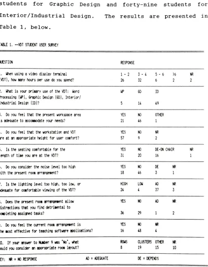
below.TABLE 1. -VDT STUDENT USER SURVEY
QUESTION RESPONSE
1. Uhen using a videodisplay terminal
(VDT),
how many hours per usedo you spend?1 - 2
26
3 - 4
32
5 - 6
6
)6
2
m
2
2. Uhat is yourprimary use of the VDT: Word
Processing
(UP),
Graphic Design(GD),
Interior/Industrial Design (ID)?
8. Does the present rooi arrangetent allow
distractions that you finddetrimental to
completing assigned tasks?
UP
5
6D ID
14 49
3. Do you feel that the present workspace area YES NO OTHER
is adequate to accommodate your needs? 21 46 1
4. Do you feel that the workstation and VDT YES NO NR
are at an appropriateheight foruser comfort? 57 9 2
5. Is the seating comfortable forthe YES NO DE-ONCHAIR NR
length of time youare at the VDT? 31 20 16 1
6. Do youconsider the noise level toohigh YES NO DE NR
withthe present room arrangement? 18 46 3 1
7. Isthe lighting level toohigh, too low, or HIGH LOU AD NR
adequate for comfortable viewing of the VDT? 24 4 37 3
YES 36 NO AD 29 1 NR 2
9. Do you feelthecurrent root arrangement is
theaost effectivefor teachingsoftware applications?
YES 16 NO 48 NR 4
10. If your answer to Number9 was
"No",
whatwould you consider an appropriate room layout?
ROUS CLUSTERS OTHER NR
8 19 15 10
[image:12.515.47.469.101.642.2]In order to observe current VDT environments in
industry,
severallocal
companies were examined, ranging insize from eight employees to over one thousand. The goal
was not to survey every
individual,
but to obtain an on-siteexamination of workstations, seating,
lighting,
and floorplan to determine current practices.
Taking
these results into consideration, andintegrating
the standards establishedby
the AmericanNational Standards Institute
("ANSI",
February
4,
1988),
adesign was developed to enhance the computer area and
improve
operator comfort. RIT is considering theimplementation of the Creative Design Electronic Media
Center,
to be housed in the present computer area. TheCenter will serve as a national center for the use of
interactive electronic media in visual communications and
will provide educational,
developmental,
and commercialservices to academic
institutions,
business,
industry
andgovernment.4
Therefore, the Computer Graphics Area was
approached as more than a
temporary
working environment forthe students;
it
was viewed as a showcase for theprogressive
technology
offeredby
computers.^"Creative
Design Electronic Media Center"1989
IV. DESIGN
CONSIDERATIONS
A. Floor Plan
The existing third floor plan of the computer graphics
area
fulfilled
thefunction
ofhousing
the VDTs, but did notprovide the
faculty
and students with an area amenable toperforming required tasks. Figure 1 depicts the existing
area with
its
completely open arrangement and lack ofdivision between user groups. This leads to distractions
when a
faculty
member is attempting to instruct a class andstudents at different workstations are attempting to
complete their assigned projects. As the survey results
in
Table 1
indicate,
the majority of respondents found thepresent room arrangement allowed for distractions and was
not the most effective for
teaching
software applications.Focusing
on these problem areas, and utilizing feedbackindicating
a preference for VDTs arranged in clustersaccording to
task,
led to the proposed floor plan(Figure
2)
. The desired goal was the separation of VDTsinto
areassegregated from the distractions of users at other
workstations while allowing users with similar projects to
interface. The proposed floor plan achieves this goal while
increasing
the number of workstations from the existing10
Faculty
members of the Computer Graphics Departmentdesired
anincrease
in
the number of Macintosh IIworkstations
in
Room3510,
from five toten,
to allow forfuture
growth. The Macintosh lis receive a great deal ofuse and
in
the proposed floor plan were separated into twoclusters to accommodate the expansion. All cluster groups
of the same manufacturer are separated from circulation
areas and other cluster groups
by
82 inch high partitions inorder to reduce distractions from adjoining areas. Within
cluster groups of the same manufacturer (See Figure
2)
, 60inch high partitions were used between VDTs that were placed
back-to-back to reduce operator distractions for these
users, but a 30
inch
partition was used in the middle toallow visibility (Macintosh II and PGP/Artronics
-Figure
2),
enablingfaculty
to communicate with students atadjoining clusters.
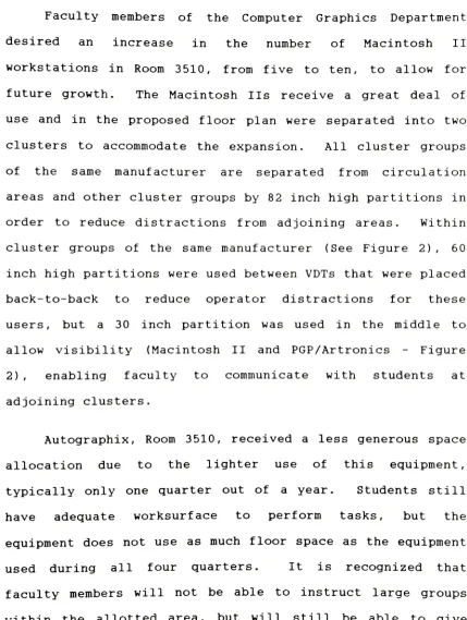
Autographix, Room
3510,
received a less generous spaceallocation due to the lighter use of this equipment,
typically
only one quarter out of a year. Students stillhave adequate worksurface to perform
tasks,
but theequipment does not use as much floor space as the equipment
used
during
all four quarters. It is recognized thatfaculty
members will not be able toinstruct
large groups [image:15.515.36.465.95.664.2]11
personalized attention as needed. A recommendation for
group
lectures
anddemonstrations
will be made later in thispaper when
discussing
the conference/lecture area in Room3500.
Relocation of the IBM PC workstations was considered
mandatory; the current location
by
the entry into Room 3510makes
distractions
inevitable
(Figure1)
.There,
workstations are completely exposed to a continuous flow of
traffic
by
those entering and exiting the room. In theirplace would be the
lockers,
relocated from Room3500,
usedby
the Graduate Computer Graphics students to storesupplies.
Placing
the IBM PCs in a cluster gives them anidentifiable work area with far fewer distractions. The
proposed IBM PC cluster was also located adjacent to the new
Intergraph location because of the similarity between user
groups, a majority coming from the Interior/Industrial
Design program.
Intergraph equipment was relocated from Room 3496 to
Room 3510 and placed in a fixed area
in
order to controlenvironmental conditions.
Autographix,
MacintoshII,
PGP/Artronics, and IBM PCs do not require as stringent
environmental control as does the Intergraph.
Many
major12
that are able to communicate with each other in order to
improve
efficiency
and reduce costs.Rising
costs of travel(airfare,
hotels,
meals, etc.), unproductive man-hours whiletraveling,
andinaccuracies
in
dissemination of information(one
persontaking
notes anddistributing
to others) aremaking
it
more attractive for companies to link workgroupsby
computer. Xerox Corporation's Palo Alto Research Center("PARC")
is an excellent example of the development of thistechnology. PARC's Intelligent Systems
Laboratory
createdan environment for computer work groups called
Colab,
withthe Colab workstations connected over an Ethernet network.
With this concept
becoming
a reality, establishing anindependent area for the Intergraph equipment allows
faculty
of different departments to simulate
industry
conditions.The College of Fine and Applied Arts Intergraph workstations
are already linked to the Intergraph workstations located in
the College of Engineering, opening up the possibility of
interdepartmental projects. Designers and engineers work
together on many projects in
industry,
and should beginexperiencing collaboration while in college.
13
B. Design Plan
Removal of the Intergraph equipment from Room 3496
allows the Genigraphics and related hardware to have a
dedicated
workspacein
that room. Partitions are used tocreate a vestibule and a private PGP/Genigraphics area used
primarily
by
graduate students, to reduce distractions andcreate a more productive
teaching/learning
situation.Genigraphics hardware requires environmental control and
by
creating a dedicated space, lectures can be given in this
room to groups with a common goal.
The conference/lecture room, Room 3500 (Figure
2)
asproposed, will take on a more formal appearance as well as
serving fewer functions. Currently, Room 3500 is used as
the graduate
students'
room, lecture room, conference room,
drafting
room; it contains lockers for storage, a lunch roomcomplete with sink, and a general meeting area. With the
shortage of classrooms
in
which lectures can beheld,
it
isrecommended that Room 3500 become a conference/lecture room.
A locker area,
drafting
area, and kitchenette were createdin
Room 3510 (Figure2)
providing the students andfaculty
with the same facilities previously found
in
Room3500,
14
would allow for removal of the sink,
lockers,
anddrafting
tables from Room
3500
and provide a larger lecture area.An even more
impressive
environment would be createdthrough utilization of the School of American Craftmen's
Woodworking
and Furniture Design Program. Students could becontracted to design and build storage cabinets,
tables,
pedestals for slide and movie presentations, and a
conference table. The conference table should be of a
sectional design
that,
when separated, forms a 2 foot-6 inchby
24 foot table to be placed against the wall, opening upthe floor space for chair arrangements
during
lectures.Demonstrations of various equipment capabilities can be
improved
by
transporting
a VDT into this area and thenprojecting the demonstration onto a screen. Lectures often
have more impact when
twenty
to twenty-five students are notcrowded around a twelve inch monitor
trying
to see what isbeing
discussed.The addition of a
technician,
stationedin
Room3509,
would improve efficiency and security and add to the overall
professionalism of the computer graphics area.
Presently
this room
is
used to house aVDT,
manuals and miscellaneousarticles related to the computer graphics area. The
15
maintenance of the equipment,
helping
with software problemsand assisting
faculty
members.Locating
a technician inRoom 3509 would make that person easily accessible to
students and the technician's visibility would discourage
less-qualified
users from attempting to tamper with theequipment.
C. Detail Considerations
In the
design,
application of accenttrim,
flooring,
and window coverings were used to
bring
Room3510,
Room 3500and Room 3496 together as a cohesive unit. The present
scheme is
lacking
in interest and does not provide astimulating environment. It is too institutional in
appearance for the image this area should project. If the
Creative Design Electronic Media Center is to serve as a
consulting, research and production unit to outside
education,
business,
industry
and government, it should havegreater appeal to its constituents.
All of the businesses surveyed used color to enhance
the environment. From Figures
3,
4,
and5,
it can be seenthat a two tone color approach was adapted for Rooms
3496,
3500 and 3510. A
darker,
less reflectivefinish
was used onthe part below the wooden fluorescent cove with a
lighter,
16
be used as tack surfaces, of the same color as the lower
wall section
(Figures
3 and4)
were specified. Use of thesecolors creates a more pleasing visual environment, but not
so
bold
as tobecome
distracting. TheIlluminating
Engineering
Society
(IES)
Lighting
Handbook recommendsreflectances of 40 to 70 percent for partitions, 50 to 70
percent for walls and 25 to 45 percent for furniture.
Wooden floors were selected for Rooms
3496,
3509 and3510 to give a richer appearance and reduce the chance of
electrostatic discharge to equipment. From the companies
visited and from research conducted, no standard
flooring
material was found to be preferred. Wood accent trim for
fluorescent coves, window coverings (Figure
3)
and furniture(Room
3500)
was another design element used to unify thearea. Conference/lecture room 3500 (Figures 2 and
5)
remains carpeted in order to reduce noise
during
presentations and meetings, and to retain a more business
like appearance.
Many
feel thattotally
covering a window should be alast resort and none of the businesses
interviewed
totally
enclosed windows.
However,
this was consideredjustified
^Illuminating
Engineering Society of NorthAmerica,
IES Lighting Handbook, (New York: Illuminating
Engineering
17
for Rooms
3510
and 3496. Peoplein
industry
tend to be attheir assigned area for greater periods of time and derive
pleasure from viewing the outside. The majority of students
(Table
1)
spend less than four hours at a timein
these tworooms, and the
horizontal
blinds were observed to be closedto reduce glare, seeming to
justify
eliminating the windows.Three of the most popular window coverings are dark
film,
louvres or mini-blinds, and curtains. All threemethods tend to reduce veiling and specular reflections, as
well as obscure views beyond the window.
Using
the windowenclosures as a potential design element, instead of
employing conventional
treatments,
was consideredappropriate. A fabric
face,
using the lighter color of thearea above the fluorescent cove, was chosen to cover the
complete window, and create the
feeling
of the upper portionspringing up from the lower part of the wall. Wooden grids
were then placed on the section below the fluorescent cove
(Figure
3)
to create the impression of the window stillexisting.
It
is
acknowledged that covering the windows wouldeliminate a source of ventilation in Room 3510. Fluorescent
7Martin
G. Helander, "Design of Visual Displays," inHandbook of Human Factors, ed. Gavriel Salvendy (New York:
18
fixtures
with air supply/air return (through side slots) ora ceiling-mounted air
handling
system similar to thatcurrently
in
placein
Room 3496 should be installed toprovide ventilation. Horizontal blinds were selected for
Room 3500
(Figure
5)
, using the lighter color of the sectionabove the cove, as the only VDT usage in this room would be
19
V.
FURNITURE
A.
Workstations
Interestingly,
only four out of the seven companiesvisited used adjustable workstations, and the majority of
students
(Table
1)
surveyed felt that the workstations wereat an appropriate height for user comfort, though
they
arenot adjustable. This perception could be a result of the
short durations of student use. It is recommended that the
computer graphics area be equipped with adjustable
workstations, not only to
help
accommodate a wide range ofphysical sizes, but to make handicapped access easier.
Adjustable workstations allow users to find worksurface
heights that are more acceptable to their particular
body
size and
help
alleviate any undue strain. This is criticalfor operators who are working with a VDT for prolonged
periods of time. As Grandjean points out, the operators'
movements are restricted, and their attention
is
directedtoward the screen,
leading
to ergonomic shortcomingssThe
seven companies surveyed were InternationalBusiness Machines Corporation
(Endicott,
NewYork),
Telesis(Rochester,
New York), Sax(Rochester,
NewYork),
Rochester Products (Rochester, New York), Arctan(Rochester,
NewYork), Xerox Corporation
(Rochester,
New York), VisualIn-Sietz (Rochester, New York). Additionally, Alfred
University was visited to obtain an overview of another
20
attributed to uncomfortable
furniture,
such as unsuitabledesk
levels
that cause constrainedpostures.9
The
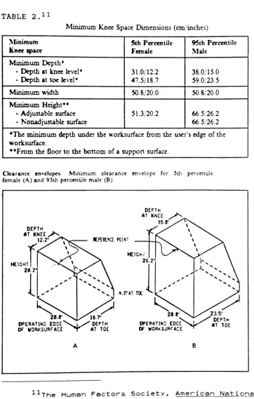
workstations should be adjustable to accommodate the
clearance envelopes for the 5th percentile female and the
95th percentile male, as specified
by
the Human FactorsSociety. Table 2 lists the requirements for
depth,
width,and height under worksurfaces, with the resulting clearance
envelopes
illustrated
beneath. In addition, thedisplay
support surface should be located such that "the
top
line ofthe
display
is not above the horizontal plane through the"10 eyes. ""
Eliminating
the variety of workstations currentlylocated within this area will add greater continuity and
improve the overall appearance. Warm gray, with a
reflective value of less than 50 percent, was the color
specified for all workstations and accompanying tables in
Rooms
3496,
3509 and 3510. As Grandjean
recommends todesigners of VDT workstations, "Select colors of similar
brightness for the different surfaces, replace eye-catching
9Etienne
Grandjean, "Design of VDTWorkstations," in
Handbook of Human Factors., 1360.
lclThe
Human Factors Society, American NationalStandard for Human Factors Engineering of Visual
P.isp_lay_
Terminal Workstations (Santa Monica: The Human Factors
[image:25.515.41.469.102.562.2]21
TABLE 2.11
Minimum
Knee Space Dimensions(cm/incbes)
Minimum Kneespace 5th Percentile Female 95th Percentile Male
Minimum
Depth*-
Depth
at kneelevel*-
Depth
at toelevel*31.0/12.2 47.5/18.7
38.0/15.0
59.0/23.5
Minimumwidth 50.8/20.0 50.8/20.0
Minimum
Height**- Adjustable surface
Nonadjustable
surface51.3/20.2 66.5/26.2
66.5/26.2
Theminimumdepthundertheworksurface fromtheuser's edge ofthe
worksurface.
??Fromthe
floor
to the bottom of a support surface.Oerjice envelopes Minimum clearance envelope for 5th percentile femaJe (A)and 95th percentile male (B)
DEPTH AT KNEE
12.? EFERE.1CE POINT
2B.E EDGE OF WORKSURFACE
HEIGH f
t.O-AT TOE
OPERATING EDGE^s. ,_ ' Di X AT is.r DEPTH TOE OPERATING EDGE
OF WORKSURFACE
N^r
11The
Human Factors Society, American NationalStandard, ANSI/HFS 100-1988. copyright 1988 by the Human
[image:26.515.40.402.76.645.2]22
effects with
black
and white contrasts, avoid reflectingmaterials and give preference to dim colors."12
He further
suggests that reflectances
(percentages
of reflected lightwith respect to
luminous
flex)
for keyboards be 30 to 40percent,
hard
copy 70 to 80 percent, monitor enclosures be20 to 30 percent, and the monitor 5 to 8 percent.13
Workstations with an independent adjustable keyboard
support surface are available, adding even greater
flexibility
for the VDT operator. If these workstations aredesignated,
the ANSI statesthey
shall range in height fromat least 58.5 cm to 71.0 cm.14
It must be remembered that
these are the minimum requirements, for Grand
jean,
Hunting
and Pidermann found
in
their field studies that the range ofadjustability should lie between 65 cm and 82 cm.15
These
were not recommended due to the short duration spent
by
students and in turn the full benefit would not be realized.
12Grandjean,
1372.13Ibid.,
1373.14-rne
Human Factors Society, American NationalStandard, 47.
15E.
Grandjean, W. Hunting and M.Pidermann,
"VDTWorkstation
Design"
Preferred Settings and their
Effects,
:23
B.
Monitor
Screens
Several
currently
marketed solutions for reducingscreen reflection were
investigated
to determine the overallbenefit
to the operator. There are disadvantages associatedwith screen filters and treatments. Neutral
density
(gray)
filters have less character
luminescence,
color filters(same
color as phosphor) have less character luminance as doPolaroid
filters,
and non-embedded filters become dirty.Micro mesh and micro louver both demonstrate limited angle
of visibility. Quarter-wavelength anti-reflection coating
is expensive and difficult to maintain, matte
(frosted)
finish of screen surface increases character edge spread
(fuzziness,
increased veiling reflections), and CRT screenhold makes it difficult to avoid shadows on screens.16
It
must be acknowledged that each of these techniques also has
advantages which in some applications may be
justified,
butdue to the
disadvantages,
none are recommended for thisdesign. Students often use their fingers as pointers,
increasing
maintenance, anddecreasing
screen filtereffectiveness even further. It
is
best to controlreflections and glare
by
proper reflectance values of theenvironment and lighting.
26
C.
Seating
Well-designed
seatingis
essential, for it is assumedthat the operator will perform the tasks while seated as
opposed to standing for the complete work day. A chair that
offers a positive effect on posture, circulation and spinal pressure is necessary.
Two types of seating are currently available to
students in Rooms 3496 and 3510. First is an ergonomic chair with tiltable seat, casters, fixed
back,
and fabricseat and backrest. The second
is
a stackable chair with plastic seat andbackrest,
offering no adjustments or casters.Survey
results show that the students found bothtypes of seating acceptable for the length of time
they
were at the VDT (Table1)
. The business survey showed that allcompanies utilize ergonomic chairs with five-star bases and
17 casters, as recommended
by
the Human FactorsSociety
.The proposed design calls for the use of ergonomically
designed chairs with controls that are easily accessible to
encourage use, five-star bases with casters for mobility,
and fabric seats and backrests to allow the
body
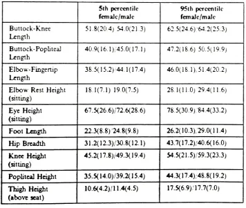
to breathe. The chair should accomodate the 5th percentile female and25
the
95th
percentile male(Table
3). The fabric should havea texture that does not
impede
shifting of thebody,
but notso smooth that it
is
difficult to retain a position.Armrests are optional; some people prefer them while others
find that
they
interfere
with lateral movements.Adjustable backrests are one feature to consider in
chair selection. The backrest should adjust backward and
forward,
up and down.Having
the seat back properlyadjusted helps to maintain the proper curvature of the spine
and possibly reduce the amount of weight on the spine.
Maintaining
poor posture for extended periods of time couldcause deformation of the spinal disks. "Chairs that
incorporate seat back angles greater than 105 degrees should
have backrests sufficiently high to provide adequate support
to the upper trunk, head and neck.
Grand
jean,
Hunting
andPidermann,
in
their survey,found that "trunk inclinations approximate to a normal
distribution. The 95% confidence
interval
liesbetween
97and 121
degrees;
the majority of the subjects preferred18International
Business MachinesCorporation,
HumanFactors of Workstations with Visual Displays
(San
Jose: IBM26
TABLE 3.19
Anthropometric Values in cm
(inches)
5th percentile female/male 95th percentile female/male Buttock-Knee Length
51.8(20.4) 54.0(21.3)
62.5(24. 6)/64.2(25.3)
Buttock-Popliteal
Length
40.9(16.1)/45.0(17.1)
47.2(18.6)
50.5(19.9)
Elbow-Fingertip
Length
38. 5(15.2)<44.
1(17.4)
46.0(18.1),51.4(20.2)
Elbow Rest Height
(sitting)
18.1(7.1) 19.0(7.5)
28.1(11.0)
294(11.6)
Eye Height
(sitting)
67.5(26.6)/72.6(28.6)
78.5(30.9)/84.4(33.2)
FootLength
22.3(8.8)
'24.8(9.8)
26.2(10.3)/29.0(11.4)
Hip
Breadth31.2(12.3)/30.8(12.1)
43.7(17.2)/40.6(16.0)
Knee Height
(sitting)
45.2(17.8)/49.3(19.4)
54.5(21.5)/59.3(23.3)
Popliteal Height
35.5(14.0)/39.2(15.4)
44.3(17.4)/48.8(19.2)
Thigh
Height (above seat)10.6(4.2)/!
1.4(4.5)
17.5(6.9)/17.7(7.0)
19The
Human Factors Society, American NationalStandard, ANSI/HFS 100-1988. copyright 1988 by the Human
[image:31.515.38.394.260.561.2]27
trunk
inclinations
between
100 and 110 degrees.Only
10%demonstrated
an upright trunk posture."20VDT operators
instinctively
prefer abackward-leaning
trunk posture andignore
the recommended upright trunk position. Anexplanation for this can be found in a study conducted
by
Swedish orthopedists wherein
they
measured the pressureinside
theinvertebral
disks as well as the electricalactivity of the back muscles in relation to different
seating postures. Subjects exhibited a decrease of the
intervertebral
disk pressure and of the electromyographicactivity of the back
by
increasing
the backrest angle of thepi seat from 90 to 110 degrees.
Seat depth should fall into the 15 to 17 inch range,
with seats whose depth exceeds 16 inches providing relief to
the back of the knee.22
Frequent changes in the users'
position are to be expected, and the seat should permit a
majority of the user's weight to be transferred to the seat
through the buttocks. A "waterfall" contour on the seat's
front edge is also beneficial in reducing excessive pressure
behind the knee and under the thigh.
20Grandjean,
Hunting and Pidermann, 170.21Ibid.,
174.22The
Human Factors Society,AjB.ericajn_.riaii.onal..
28
An adjustable seat height of 16 to 20.5 inches is
recommended
in
providing operator comfort.23It is
desirable
for the operator's thighs to be reasonablyhorizontal,
lower
legs vertical and the feet plantedfirmly
on the floor. Operators whose height is such that the
16
inch
minimum is still too great might require a footrest.Selection and placement of a footrest should be such as not
to
impede
operator movement or mobility within theworkstation, but still be convenient enough to provide
adequate support.
23Ibid.
29
VI.
LIGHTING
Lighting
is one area that should be reexamined whenconverting
a workplace from traditional task usage toaccommodate VDTs. Traditional tasks in the office
environment are usually performed on a
flat,
horizontalsurface with high contrast between paper and printed
characters.
Generally,
these work spaces were designed withuniform
lighting
levels,
which in itself can cause fatigue.However,
if workers experienced any discomfortthey
alteredtheir sitting positions.
Lighting
for VDTs must be approached in a differentfashion. Users are now confronted with a VDT work surface
that is placed in a near-vertical position and is curved
rather than flat. This positioning and configuration
creates problems with direct glare and reflected glare, as
this surface is struck
by
light rays that would normally gounnoticed
if
performing tasks at a traditional workstation.To further complicate the application, ". . .a typical
VDT screen's surface consists of polished transparent glass
30
between
the two."24Light rays
hitting
the screen's face oraluminum
backing
can cause specular reflections capable oftotally
obscuring
thedisplay.
These reflections might becaused
by
the user, a chair, windows, or any otherreflective object
in
the work space. Diffused reflectionsare caused
by
light rayshitting
the irregular surface ofthe phosphor coating,
degrading
visibilityby
reducing thedetails of the
display
andits
background.Developing
alighting
plan to address only the problemsof direct glare and indirect glare will not be adequate as
the VDT is generally located in a workspace where other
tasks,
which require differentlighting
levels,
arebeing
performed.
Many
lighting
options are available and wereanalyzed to determine which would be the most
beneficial,
orif a combination of options would yield the best results.
The National
Lighting
Bureau suggests considering theoptions of illuminance adjustment,
lighting
colormodification, installation of controls,
luminaire
relocation, luminaire modification and
luminaire
OK
replacement. J
24National
Lighting Bureau, Solving the Pu2 2.1.e_____yDT, Viewing Problems (Washington, D.C.: NationalLighting
Bureau, 1987), 6.
31
Illuminance
adjustment should be taken intoconsideration
if
the generalilluminance
of a work area istoo
high.
Roughly
speaking, a VDT workstation need not havelevels
greater than 75footcandles
("fc").26Recommended
differences
in
luminance
between the task area and itsimmediate
surrounding are no greater than 3:1 with no morethan a 10:1 difference between the task area and more
distant surroundings.27
It should be noted that no
scientific support is available to substantiate these
guidelines. If higher illuminance is required to perform a
specific
task,
this should be handled using tasklighting
and not
by
increasing
the level throughout the area,being
mindful that glare results from excessive contrast between
the brightness of the task and the general brightness of the
surrounding to which the eyes are adapted.
Lighting
color modification should enhance the interiorand its occupant, not the VDT. Installation of controls
leads to greater
flexibility,
allowingindividual
users toadjust illumination to satisfy personal needs. Luminaire
26Illuminating
Engineering Society, 5-13.27International
Business MachinesCorporation,
51.28Henry
J. Cowen and Peter R. Smith, Ejn_yirgnm..enta.l32
relocation
is
another option made possibleby
relocatablebranch
wiring, though whether it is as viable an alternativeas the others
is
questionable. Relocation can impact theoverall
light
distribution
of the space, affecting thevisual needs of others and the appearance of the workspace.
Luminaire modification and luminaire replacement should
be evaluated at the same
time;
both offer adequate solutionsto
lighting
problems and there would be little costdifferential between the two. If extensive modifications
have to be
implemented,
then exploring the deep-cellparabolic-louvered luminaire as a replacement could be
justified. Some consider this the best
lighting
for VDTareas.
A complete
lighting
modification was deemed necessarywhen evaluating the current
lighting
plan.Many
studentsconsidered the
lighting
level toohigh,
whereas the majorityfelt
it
was adequate for the amount of time spent at the VDT(Table
1)
. Businesses surveyed generally maintained muchlower
lighting
levels,
10 fc to 40fc,
for their operatorsthan RIT's
lighting
level of 100 fcin
room 3510. Generalillumination of 20-40
fc,
well within the IES guidelines,should be provided from high quality
(no
veiling33
reflections),
controlled brightnessluminaires,
withsupplemental task
lighting
where necessary.30The most noticeable problem area
in
Room 3510is
whereoverhead
fluorescent
lightis
provided at uniformly highlevels
throughout.
Suchlighting
may create glare, withconsequent
headache
and eyestrain; it is aestheticallyuninteresting
if
not unpleasant and it is wasteful of energybecause
it
produces more light than is needed.31It should
also be noted that
in
June of1988,
the Suffolk County, NewYork legislature passed the nation's premier bill requiring
employers to take responsibility for eye and health-related
problems of VDT operators, placing even greater emphasis on
proper
lighting
design and operator welfare. *Focusing
on lowerlighting
levels and reduction ofglare led to the proposed reflected ceiling plan
(Figure
6)
.Architectural coves (Figures 6 and
7)
are designated inareas
illuminating
theVDTs,
forthey
provide the30Mitchell
Kohn, "Lighting Offices ContainingVDTs,"
i ighi-ing Design and Architecture (December 1988): 9.
31peter
Ellis, "Functional, Aesthetic, end SymbolicAspects of Office
Lighting,"
in Behavioral Issues lQ_Qf_Lice
Design, ed. Jean D. Wineman (New York: Van Nostrand
Reinhold Company Inc., 1986), 225.
32Peter
Engle, "Encroaching laws will make proper VDT34
opportunity
tohide
lighting
equipment which,in
turn,
canilluminate
and accentuate architectural details and provideindirect
illumination
from the ceiling and walls.33In
order to capitalize on the
indirect
lighting,
a morereflective matte
finish,
approximately70%,
was used on thewalls above the
fluorescent
cove. An even higher reflectivematte
finish
is recommended for the ceiling(90%)
. Thiswill
help
to soften shadowsby
providing light from manydirections. High-reflectance matte finishes on room
surfaces become effective secondary light sources and
materially reduce shadows
by
reflecting a significant amountof diffused light into shadow areas. 4
To simply provide a horizontal plane for a ceiling
detracts from the goal of providing a stimulating
environment in this application; to end the design at a well
planned floor layout is inappropriate. Recesses are used in
room 3510 (Figures 6 and
7)
to designate circulation areasand VDT clusters, as well as
integrating
the fluorescentcoves
into
the architectural details. Circulation areas,and the Intergraph room, are equipped with 2 foot-0
inches
x2 foot-0 inches fluorescent fixtures and parabolic louvers
33Illuminating
Engineering Society, 5-4.35
to prevent uncomfortable glare
by
limiting
the light outputat angles greater than 50 or 60 degrees from vertical in the
case of
fluorescent
luminaires
.35
Fluorescent
coves were used exclusively in Room 3496(Figure
6)
to provideillumination,
combined with a recessedceiling over the circulation area for
interest.
The samefinish requirements as in Room 3510 were specified to reduce
shadows and glare. A more conventional approach was taken
in the conference/lecture Room 3500 due to it
being
asmaller area with the possibility of seating arrangements
and functions changing frequently.
Providing
alighting
scheme that allows for varying luminance is recommended.
This can be accomplished
by
the installation of separatecontrols for the different fluorescent banks.
Task
lighting
to illuminate hard copy at theworkstation (Figure
7)
is
left to the discretion of theoperator. Task
lighting
which would secure to documentholders and limit the effects of transient adaption and
disability
glare, should be made available to the students.The IES recommends that luminance ratios should not exceed:
36
Paper-base
task to VDT screen 1 to 1/3Task and adjacent dark surroundings 1 to 1/3 Task and adjacent light surroundings 1 to 3 Task and more remote darker surfaces
Task and more remote lighter surfaces
1 to
1/1Q,
1 to 10. 36The task
light
in
this design would be a highintensity
discharge
"point source"luminaire,
one that limits thelight output at angles treater than 45 degrees.37
Designing
a comfortable workstation and environment forthe VDT operator will
help
provide the necessary conditionsto improve productivity.
Ignoring
the operators'working
conditions on the premise that
they
were adequate orstandard to perform traditional tasks is shortsighted and
could lead to employee health problems and lawsuits.
36Ibid.,
5-14.
37
II. NOISE
Acoustic noise
is
another area of concern from anengineering as well as human factors standpoint. The Human
Factors
Society
believes that VDT workspaces should not besubjected to sound pressure levels greater than 55 dba,
excluding noise generated
by
the user.38The Occupational
Safety
and Health Act regulations set level standards thatvary from 90 dba for operators with eight hours of exposure
per
day
to 115 dba for those with .25 hours or less perday.3
Clearly,
sound levels acceptable to the medical profession are considered too high from the human factorsviewpoint.
Eliminating
all white noise, ambient orbackground noise, is also undesirable as such sounds not only
help
to muffle unwanted noise, but a complete lack of ambient noise could be disconcerting. Alternatively, if the ambient noise exceeds the 55 dbalevel,
it could have anadverse affect on productivity, creating speech interference and unwanted distractions.
Existing
sound pressure levels establishedby
the HumanFactors
Society
are not exceeded in the computer graphics38The
Human Factors Society, ArnejrJ^ajn__NaMonaiStandard, 14.
38
area, even through the students consider the noise level too
high
with the present room arrangement (Table1)
.Establishing
cluster groups and a circulation area, mostnotably in Room
3510,
will decrease distractions and39
VIII. SUMMARY
Organizations,
large
and small, are recognizing thebenefits
associated with providing a work environmentdesigned
with employees'welfare in mind. To gain the maximum
benefits
from today'stechnology
VDT operators must be comfortable with their workstations and environment. RIThas the capability to educate students academically and to
develop
an awareness of and the ability to shape future work environments. Graduates of the Institute can be a major factorin
recruiting talented people. If graduates have been dissatisfied with their environment,they
candiscourage applicants as well.
Minoring
in Computer Graphics has exposed me to a very capable and talentedfaculty,
but the classroom and equipment need to be broughtup to a higher standard.
The student and business survey contributed a great
deal of insight to the design of this area. Much
information
is
available on the separate components comprising a VDT environment, but littleinformation
exists that ties it all together. Itis
possible for manycombinations to provide a user-friendly environment, but the combinations must be suited to the group spending time in
40
feedback
from users be obtained, whether for a classroom orbusiness
setting.VDTs are
becoming
commonplacein
the academic environment as well as inindustry.
For the existingcomputer graphics applications, and for the Creative Design
Electronic Media Center
being
proposed, a design wasconceived
that,
in appearance and efficiency, bringseducation and business closer together. Ergonomic
considerations should not be left until a later
date;
they
should be instituted now to afford students and
faculty
the41
BIBLIOGRAPHY
Bomberg,
Hy. "Workflow/Workspace."A Series of Commentaries
on
Offices,
Productivity,
and theQuality
of Work Life.Herman Miller.
Boylan,
Bernard R. TheLighting
Primer.Ames,
Iowa: IowaState
University
Press,
1981.
Burgess, John H.
Designing
for Humans:The.
Engineering. USA: Petrocelii
Books,
Inc.,
1986.Carter,
K.J. and I. McEwan. "Obstructed Spaces in InteriorLighting
Design: Computer Analysis."Lighting Research
and_T.echnol.ogy Vol. 20 No. 1 (1988): 21-18.
Cowen,
Henry
J. and Peter R. Smith. Environmental Systems. New York: Van Nostrand ReinholdCompany,
1983.Ellis,
Peter. "Functional, Aesthetic, and Symbolic Aspects ofOffice Lighting."
In Behavioral Issues In Office
Design,
ed. Jean D.Wineman,
225-249. New York: Van Nostrand ReinholdCompany
Inc.,
1986.Engle,
Peter."Encroaching
laws will make proper VDTergonomics a must."
Contract. (October 1988): 27-28.
Galer,
I. A. R. , ed. Applied Ergonomics Handbook. Oxford:Butterworth & Co. Publishers
Ltd.,
1987.Grand
jean,
Etienne,
W. Hunting, and M. Pidermann. "VDT Workstation Design: Preferred Settings and theirEffects,"
Human Factors
25(2)
(April 1983): 161-175.Grand
jean,
Etienne. "Design of VDTWorkstations."
In
Handbook of Human Factors, ed. Gavriel
Salvendy,
1360-1397. New York: John
Wiley
andSons,
Inc.,
1987.Helander, Martin G. "Design of Visual
Displays."
In Handbook
of Human Factors, ed. Gavriel Salvendy, 508-619. New
York: John
Wiley
andSons,
Inc.,
1987.Illuminating
Engineering
Society
of North American. IESLighting Handbook. New York:
Illuminating
Engineering
42
International
Business
Machines
Corporation. Human Factorsof
Workstations
with Visual Displays.San Jose: IBM
Human
Factors
Center,
1984.Kleeman,
WalterB.,
Jr. "The Office of the Future."In
Behavioral__Issues
In OfficeDesign,
ed. Jean D.Wineman,
251-289.
New York: Van Nostrand ReinholdCompany
Inc.,
1986.
Kohn,
Mitchell."Lighting
OfficesContaining
VDTs."Lighting
Pj^signajid_.Arjchi_tectujre.
(December
1988): 9-11.McKeon,
Richard F."Herman
MillerFacility
Summary: DataProgrammer Work Station Mockup."
(Draft).
National
Lighting
Bureau.Solving
the Puzzle of VDTViewing
Problems.
Washington,
D.C.: NationalLighting
Bureau,
1987.
Nemiecek,
Jan and Etienne Grandjean. "Results of anErgonomic Investigation of Large-space Offices."
Human
Factors
(April
1973): 111-124.Rochester Institute of Technology. "Creative Design
Electronic Media Center"
Informational document.
Rochester,
NewYork,
1989.Ryburg
, Jon B. The Office as a Critical Work Environment.Ann Arbor:
Facility
ManagementInstitute,
1981.Ryburg
, Jon B. VDTs
-An Immature Technology"
The for
Facility
and Management Support Standards. Ann Arbor"Facility
Managementinstitute,
1981.Ryburg,
Jon B."Technology
and the Development of OfficeWorkplace Standards for the 80 's and 90's."
Paper
presented at the Financial
Training
Seminar sponsoredby
Herman Miller,Inc.,
July
22,
1981.Shea,
Kelly. "For times when two heads are better than one."Computerworld (March
14,
1988): 2.The Human Factors Society. JProceedinqs of the Human Factors
Society 25th Annual Meeting.
Rochester,
1981.The Human Factors Society. American National Standard for
43
Workstations.
Santa Monica: The Human Factors Society,1988.
U.S. Department of Health and Human Services, Public Health
Service/Center for Disease Control. HHS__Publ_i cation_J
No,
(CDCJ
. Atlanta: Center for Disease Control,1980,
307-308.
Wineman,
Jane D. "The Importance of Office Design toOrganizational Effectiveness and
Productivity."
In
Behavioral Issues
in
OfficeDesign,
ed. Jean D.Wineman,
ix-xvii.
New York: Van Nostrand Reinhold>ncnc
JO
W
8
08:
e
:>
5
ee
i
ffi
btzpo
^
n
i i
r
an
la?
95
ffiffl
r
ffi!
r
4
IS
s
m&m
n
" 8 [-1na
LUj-
*
J
U
ie
ee
n
s
-i
n
Hi
k
\J
i=i j D>a
I
I
at
)
to-L
J
a
r=!
w
$
|
ILI
?
\
a
a
J
K
;