International Journal of Innovative Technology and Exploring Engineering (IJITEE) ISSN: 2278-3075, Volume-8 Issue-6S, April 2019
Abstract: Contemporary growths in intelligent management ways has paved way to interlinking of PV initial Converter which stabilizes and interlinks it to drives which works based on Alternating Current. Sequential boost convertor and electrical converter find there purpose in interrelating natural energy source with drive based alternating current Induced Motors. Work carried out in this paper pacts with graphical system based results which is used to correct the harmonics and impurities present in the system resulting in improving the quality of the power in the resultant output. Using a sequential high efficient step up converter the output from the natural energy source will be improved significantly. The DC output of those series step up converters is set to the bridges of the series electrical converter. A sequential order of inverters arranged in five level order is used to produce the high improvement in Alternating current. Sequence converter implied in step up is analyzed using the induced motor as load. Un-interrupted monitoring of the system is carried out through the implementation of fuzzy logic controller. Corrections on the errors based on steady state are carried out using FLC. The simulated outcomes assure the difference in dynamic retort in terms of dropping time along with errors which occur due to steady state.
Keywords: DC to AC converter, Boost converter, PV system, Fuzzy Logic Controller (FLC)
I. INTRODUCTION
Current pattern is to support for environmentally friendly power vitality built inverter which contexts for high-control applications and uses. PV based MLI’s exhibits/energy units on the information turn out to be great options in contrast for the battery based inverter concepts. Distinctive circuits based on different options are recommended for MLI’s; the very well-known circuits of them are diode-braced structures as discussed in [1].
The regulation parts best suited for the MLI’s are referred from [2]. Different utilizations for the MLI used for high power-uses were enrolled with the auto-voltage monitoring and controlling to a summed up MLI has been recommended by [3]. The power based on MLI transformation framework is portrayed and a review on MLI has finished utilizing single DC source novel strategy for CMLH Bridge-Drive was explained in [4]. A simplified technique based on diode clamped MLI is shown with a streamlined technique of DC- AC conversion based MLI, MLI based electrical uses and applications with a wide
Revised Manuscript Received on April 10, 2019.
spread structure of structure Power convertor was demarcated Cascade Voltage-source electrical converter with separate DC supply with a brand new MLI topology with a hybrid approach. A H-bridge based single phase convertor for renewable systems given by a brand new combined FLC was delineated by The inoculation of real power 5 level electrical converter is by author Shen et al. Five-level inverters are used in star structures is attributable to minimum harmonics, inductance value is reduced, and reduced impurities when compared to three-level inverters. Benefits of using 5 three-level MLI with a varied five-level inverters, is delineated by the authors [5]. Power factor which was designed based on a DC stabilization. Inverters with traditional four switch are utilized, however they create warmer because of sounds productive approaches to improve the power in [6] clarified about another Multi five-level inverter system with CMS reduction for IM.
[7]Had said about another staggered DC-interface three-stage five step voltage source topology. Staggered DC connect created adjusting intensity appropriation in the info cells utilizing stage moved PWM.
[image:1.595.306.551.485.639.2]Voltage levels have been triggered at different levels and harmonics have been compared between asymmetrical and symmetrical patterns, the comparison study carried out in [8-9] shows the superior pattern with regard to multilevel inverter.
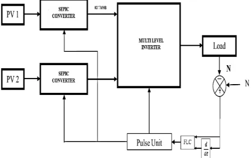
Fig. 1 Block representation of proposed system with FLC
II. DESIGN AND IMPLEMENTATION OF PROPOSED SYSTEM
The proposed system methodology and principle of design is also explained in this section. The important methods also elaborated in this section.
Five-Level Inverter based Sequential Boost
System using Fuzzy Logic Controller
A. Need For Multi-Level Inverter
In developed society many manufacturing uses have need for great power. Various uses based on manufactures entail standard or decent power for the production consumption. By means of entailed power the requirement for all manufacturing requirements be beneficial to few equipment’s which may use improved power, there is a chance that it might be a threat to the additional power consumers. Few medium voltage manufacturing drives and normal applications require average voltage. MLI has paved a path for the high power manufacturing industries to improve the production levels since MLI’s are the type of inverters implied in heavy duty industries with the requirement for load is high. This is a convenient and efficient alternate to customized inverters which may not have efficiency has high.
B. SEPIC Converter
SEPIC is a type of converter which is capable of handling the voltage either ways. Either ways in regard as increasing the actual voltage to better level or decreasing the voltage to the minimum possible level. The control over this type of system is attained through soft switching techniques by varying the duty cycle or duty ratio and Time period. Generally this type is used before the inverter circuit such that the stabilized power could be fed to the protracted system. With respect to this proposed system a reference voltage will be set and the converter will be made to work constantly in respect of reference voltage.
C. Fuzzy Logic Controller
Controller is a backbone to the whole system, in this work we have incorporated artificial intelligence based control. The whole system works on the logics and conditions based on True or False. The advantage with logical control system is
once the logic has been set, repeated monitoring isn’t needed. Based on the logic, whole system keeps working in a loop or round the clock structure until the desired value is attained with respect to the set or reference value. The artificial intelligence based controller used in this work is compared with a traditional or olden type of analog controller, the analog controller taken in reference is PID type system of control.
D. PID Controller
An Analog technique based controller, which used to be traditional way of controlling electrical systems. With the development in soft switching / digital control techniques, this type of controllers have started to extinct.
The system proposed in this work is considered efficient with the use of artificial intelligence control technique, as a reference to prove that PID is implied in the work with the simulated works. Analog Controller calculation includes three separate consistent parameters, and is in like manner at times called three-term control: the corresponding, the necessary and subsidiary qualities, meant P, I, and D.
Basically, they are based on the mathematical variables such proportional which is responsible for controlling, integral as a quantity with respect to working period and derivate will be the set value constant provided to be the warning component.
III. SIMULATION OF PROPOSED SYSTEM
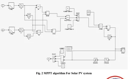
[image:2.595.85.531.486.751.2] With Regard to simulation of discussed work, a simulated circuit has been run using S- link Simulation software. The simulated proposed system has two cases. The MPPT algorithm for the discussed work is as shown in the figure 2.
International Journal of Innovative Technology and Exploring Engineering (IJITEE) ISSN: 2278-3075, Volume-8 Issue-6S, April 2019
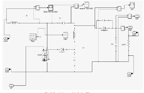
[image:3.595.61.534.78.385.2] The solar based renewable component modeled is depicted in the figure 3. Replica of real time model.
Fig. 3 Simulation model of solar PV system
The discussed Analog controller is also simulated is as depicted in the figure 4.
Fig. 4 Simulation model of PID controller
Fig. 5 Multilevel inverter simulation model
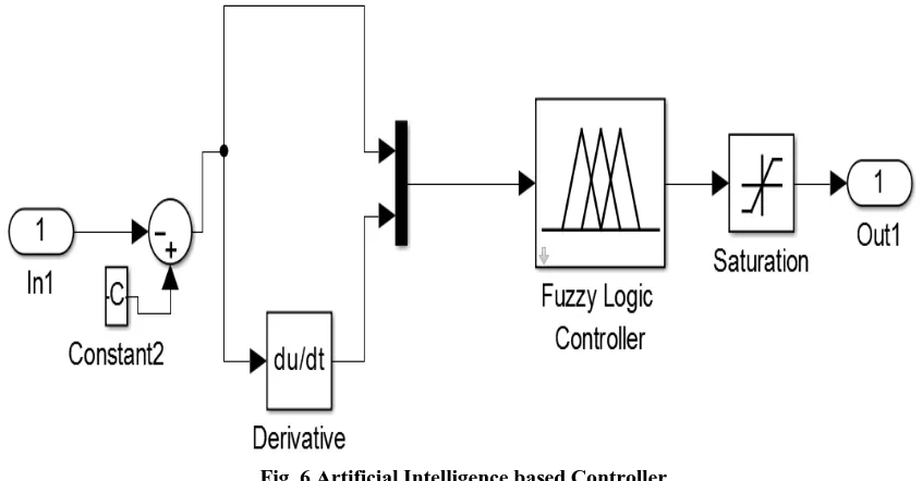
In the second case the fuzzy is implemented for generating PWM wave generation the simulated Fuzzy is designed as depicted in the fig6.
Fig. 6 Artificial Intelligence based Controller
[image:4.595.85.508.470.691.2]International Journal of Innovative Technology and Exploring Engineering (IJITEE) ISSN: 2278-3075, Volume-8 Issue-6S, April 2019
Fig. 7 Digital Controller for MPPT
Using the above simulation models complete model is created and the output results are discussed in next section.
IV. SIMULATION OUTPUT WAVEFORM AND
RESULTS
The simulation consists of two cases the output for two cases is discussed in this section.
Case 1: Output for PID Controller
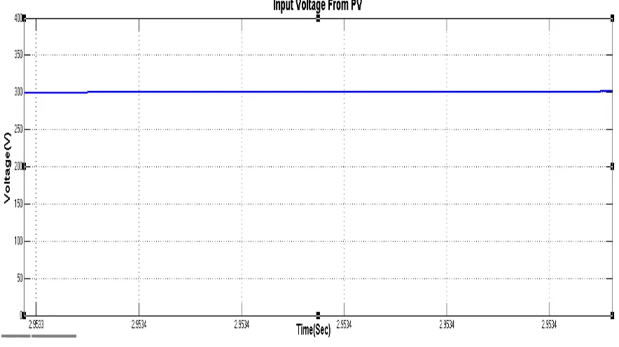
The system is simulated and successfully compiled in MATLAB simulation software. The output voltage from PV system is as shown in the figure 8.
Fig. 8 Output Voltage waveform of Solar PV System
[image:5.595.79.521.450.698.2]Fig. 9 PWM pulse generation of proposed system
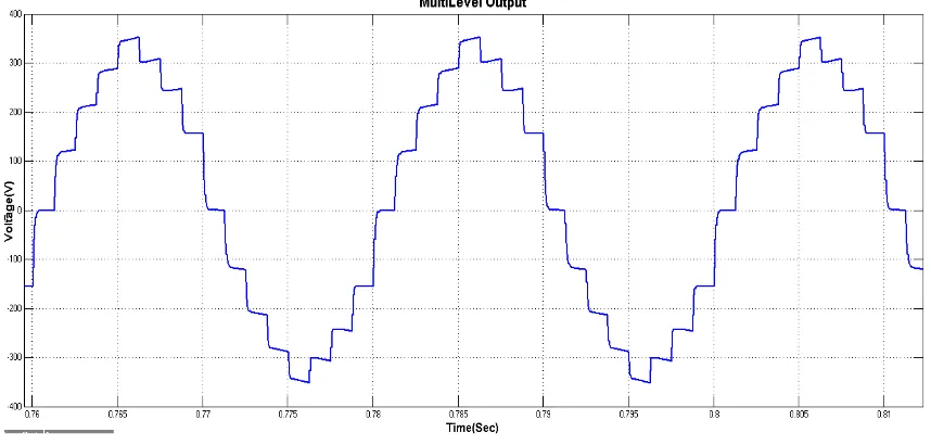
[image:6.595.90.508.284.475.2]The PID contoller ouptput Mult level inverter output. The voltage is maintained of about 320 volt AC output waveform is as shown in the figure 10.
Fig. 10 Multilevel inverter output waveform
Case 2: Output for Fuzzy
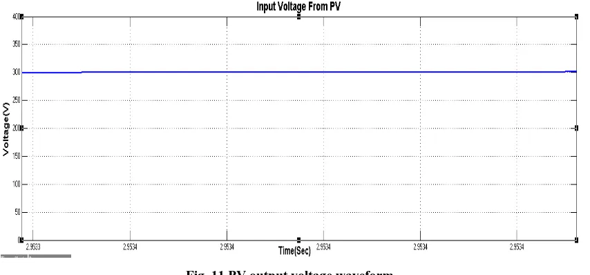
The given system is compiled based on fuzzy logic controller.
Fig. 11 PV output voltage waveform
[image:6.595.88.515.532.731.2]International Journal of Innovative Technology and Exploring Engineering (IJITEE) ISSN: 2278-3075, Volume-8 Issue-6S, April 2019
Fig. 12 Fuzzy output Pulse waveform
This pulse generated from the fuzzy is fed into the multilevel inverter the output multilevel waveform is as shown in the figure 13.
Fig. 13 Multilevel inverter output voltage waveform using Fuzzy
From the results and output waveform of this two cases the results are discussed in next section.
V. CONCLUSION
A novel parallel solar PC system is designed with respective SEPIC converter and multilevel inverter is designed in this paper for better efficiency by stepping up the level’s to N number, the stepping up will result in the improvement of the efficiency gained in the output end. Since voltage is the factor, the voltage improvement is constantly carried out.
A comparison is made between Analog type controller and digital logic based artificial intelligence controller is also simulated in this paper. The output results are as shown in the previous section.
It can be clinched, output of the proposed 5 level system from analog based controller is only of 320 Volt AC whereas
REFERENCES
1. ZeeshanAleem, and MoinHanif, Operational Analysis of Improved
Γ-Z-Source Inverter with Clamping Diode and its Comparative Evaluation, IEEE Transactions On Industrial Electronics, pp. 9191- 9200, 25 May 2017.
2. M. Poursmaeil, Sh. MoradinejadDizgah, H. Torkaman, E. Afjei,
Autonomous Control and Operation of an Interconnected AC/DC Micro grid with Γ-Z-Source Interlinking Converter, Smart Grid Conference (SGC)March, 2018..
3. Guidong Zhang, Bo Zhang, ZhongLi,DongyuanQiu, Liqiang Yang, and
Wolfgang A. Halang, A 3-Z-Network Boost Converter, IEEE transactions on industrial electronics, pp. 278-288 vol. 62, no. 1, January 2015.
4. SomasundaramEssakiappan, Harish S. Krishnamoorthy, Prasad Enjeti,
[image:7.595.85.514.314.519.2]5. Poh Chiang Loh, Ding Li, and FredeBlaabjerg, Γ-Z-Source Inverters, IEEE transactions on power electronics, pp. 4880- 4884 VOL. 28, NO. 11, NOVEMBER 2013.
6. K Dwarakesh, S Dhivya, Design And Optimization Of High Efficient
Charge Controller For A Solar Photovoltaic System Power Generation, International Journal Of Pure And Applied Mathematics,2018 119 (12), 763- 771.
7. K Dwarakesh, S Dhivya, Plan For Reliability Of Power Electronics For
Grid-Connected Photovoltaic Systems, International Journal Of Pure And Applied Mathematics,2018 119 (12), 353-359.
8. K Dwarakesh, S Anitha, Resonant Converter Fed Pmbldc Motor,
International Journal Of Pure And Applied Mathematics,2018 119 (12), 57-63.
9. K.Dwarakesh, J. Gayathri Monicka, “A Modified Topology for Three