Abstract: On account of the brisk progression of Intensity contraptions methodologies, applications with photovoltaic (PV) power and wind control have been stretched out on an exceptionally essential dimension. The use of sun controlled and wind energies openly would not give a splashed yield voltage. So the Sun powered imperativeness and Wind essentialness are set to shape Sunlight based Breeze Half breed Power Framework (SWHPS), which will upgrade the characteristics of each other. To decrease the power ask for on the standard power age locale, we propose this structure. Diverse techniques are in the end for time of power utilizing Sun oriented Breeze Mixture Framework with Greatest Power Point Following (MPPT). Persevering voltage strategy is utilized for most silly power exchange. This methodology ought to have some key highlights to produce the capability. In this paper proposes a novel method for executing MPPT controller in our cross breed manageable power source age system called as FLC figuring for best viability over various procedures. The above elucidated system is organized and reproduced in MATLAB/Simulink reenactment programming and the multiplication results were gotten.
Key words: Solar PV generation, wind energy generation, hybrid energy system, MPPT controller, FLC algorithm.
I. INTRODUCTION
As of late the number of technological improvements on the outline of models for energy power by utilizing energy sources not traditional, for example, sun based wind, hydro, biomass and bio fills, geothermal, cells powers [1]. Sustainable power sources, for example, Solar Energy and Wind energy are the sources that energy caught and put away by nature. A creating system with a solitary power source non-traditional energy [6] does not supply power required. Because of global warming, new energy sources should be utilized for example, sun oriented and wind energy. Sustainable power source is getting to be more critical. Sun oriented and Wind energy is without contamination and endless. All districts of the world have inexhaustible assets of some sort.
In this manner an examination on sustainable energies concentrates increasingly consideration [5]. Utilization of inexhaustible energy hotspots for control age numerous investigations have been done. Due to their unpredictable nature, the solar and wind energy systems are highly unreliable [2].
Revised Manuscript Received on June 07, 2019
K.Sakthivel, Research Scholar, Department of EEE, BIHER
V.Jayalakshmi, Supervisor, Department of EEE, BIHER
Other energy source can compensate for the difference, when a source is unavailable or insufficient in meeting the load demands. Due to the rapid growth of power electronics techniques applications with photovoltaic (PV) energy and wind energy have been increased significantly [4]. Basically solar radiation and wind speed are complementary profiles. The communities outside the urban centers have problems for installation, wiring because the public does not arrive to their homes.
In these cases, these vitality sources are a very doable option. Crossover framework is a superior contrasted with unusual source. As pondering these two vitality resources, the yield isn't sure a direct result of environmental or day and night conditions [9-12]. That is the yield of Sunlight based Breeze control isn't sure one may give more power and other may give less power or no power. So it required to adjust yield voltage from this framework. These two frameworks are related parallel to one another, that if one source isn't available, by then the other one can modify the framework [15]. As such, these two frameworks can work independently and in the meantime also. In this paper another technique utilizing FLC calculation for the proposed MPPT for the cross breed control framework is executed for giving better productivity and unwavering quality. The framework is demonstrated in MATLAB/Simulink reproduction programming and mimicked for the proposed framework.
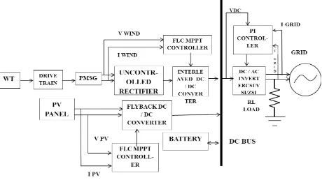
II. PROPOSED HYBRID SYSTEM
The proposed system is represented in simple in the block diagram representation as shown in the figure 1.
Maximum Power Extraction by using Converters
for Hybrid Renewable Energy Source Fed
Micro-Grid
Maximum Power Extraction by using Converters for Hybrid Renewable Energy Source Fed Micro-Grid
Fig. 1 Block representation of proposed Hybrid Renewable Energy Fed micro-grid
In this paper a noval method for MPPT controller is implemented for the purpose of better efficiency from both wind and solar power system. The method used here is Fuzzy logic Controller (FLC) algorithm. The wind turbine used here is Permanent Magnet Synchronous Generator (PMSG) with parallel connection of Photovoltaic power generation with battery bank for providing better reliability. The inverter used here is impedance source inverter which is controlled by PI controller. The power from our hybrid power system is converted from DC to AC through ZSI (Z-Source Inverter) and the extracted power is coupled with the grid. And can be supplied to the required load if needed.
Wind Power - Permanent Magnet Synchronous Generator
The turbine retrieves solely a fraction of the wind’s kinetic power. This power is decided by the area swept by the blades, the wind speed, the air density, and therefore the power constant, that characterizes every turbine. Hence, the generated mechanical power, may be expressed as follows,
Where, R is that the radius of the rotary engine. Cp may be a function of λ, the tip speed magnitude relation and β, the pitch angle ωm is that the turbine angular speed. Neglecting the friction forces, the dynamic equation of the turbine is given by,
where ωm, is that the rotating speed of the blade, P , the amount of pole pairs, J, the moment of inertia of the generator, Tm, the torque developed by the turbine and Te, the torque because of load that during this case is that the generator magnetic attraction torsion. For a permanent magnet synchronous generator, the rate of flux is
characterized in direct and quadrature with electrical torque equation is given by equation 3a, 3b and 3c respectively.
where uds, uqs and ids, iqs are the generator stator coil dq-axis voltages (V) and currents (A), respectively; Rs is that the stator coil winding resistance (Ω ); Ld and Lq are the stator coil dq-axis self-inductances (H); ωr is that the rotor electrical angular speed (rad/s); and λr is that the rotor flux (Wb) generated by the permanent magnets. Non-salient (or round) rotor PMSG is taken into account during this study, the d- and q-axis magnetizing inductions are thus equal (Ld = Lq).
Solar power Generation
Therefore, a gauge boson should be absorbed to supply the energy needed to dislodge and move electrons across the valence gap.
The global formula to estimate the electricity generated in output of a photovoltaic system is
E = A * r * H * PR (4)
E = Energy (kWh)
A = Total solar array space (m2) r = solar array yield or efficiency(%)
H = Annual average solar radiation on inclined panels (shadings not included)
PR = Performance ratio, coefficient for losses (range between 0.5 and 0.9, default value = 0.75)
Where ‘r’ is that the yield of the solar battery given by the magnitude relation: power (in kWp) of 1 solar battery divided by the world of 1 panel. Radiation=1000 W/m2, cell temperature=25 Celsius degree, Wind speed=1 m/s, AM=1.5. The unit of the ostensible intensity of the electrical marvel board in these conditions is named "Watt-crest" (Wp or kWp=1000 Wp or MWp = 1000000 Wp). H is the yearly normal radiation on slanted boards. PR (Execution Proportion) is an essential worth to pass judgment on the standard of a photovoltaic establishment because of it gives the execution of the establishment freely of the introduction, tendency of the board.
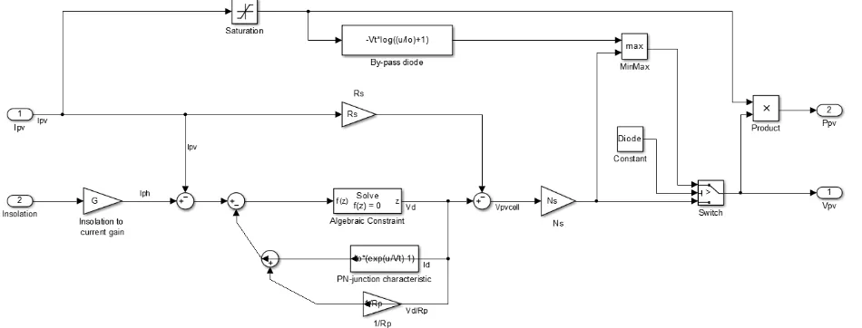
In simulation it is simulated as digital signal given to the dependent current source. This current source is controlled with the proposed mathematical model which reflects the characteristics of solar PV panel according to the temperature and solar irradiance input constants.
Microgrid
Microgrid represents a completely new approach to desegregation Distributed Energy Resources (DER), particularly tiny generators, into utility distribution systems. Ancient approaches for desegregation DER specialize in the impacts on grid performance of 1, two, or a comparatively tiny variety of on an individual basis interconnected micro generators. An important feature of the Microgrid is its presentation to the encompassing distribution grid as one manageable system. Key to the present characteristic is reliance on the flexibleness of advanced power natural philosophy that controls the interface between microsources and therefore the close AC system. The central advantage of a Microgrid is that it will be considered a controlled part inside the facility system which will be operated as one dispatchable load, which is able to respond in seconds to distribution system desires. Customers additionally get pleasure from a Microgrid that's designed to fulfill their native desires, e.g., for uninterruptible power supply/enhanced native dependability, reduced feeder losses, supported native voltages/correction of voltage sag, and exaggerated potency through use of waste heat.
Fuzzy Logic Controller
Fuzzy Logic may be a specific space of concentration within the study of computer science and relies on the worth of that data that is neither undoubtedly true nor false. No inheritable information is a robust weapon to combat the unsought effects of the system response. In most
[image:3.595.308.569.150.267.2]applications there are some points that are the common space. Data that lies among the common space needs to be studied, stored, and accustomed quantify and to classify the information. This enables for good manipulation of the information structure so as to form illation to an answer. Data that falls in this common space will be stratified, aged, and "best guess" created when analysis of this "gray" data.
Fig. 2 Fuzzy controller Working Method
There are specific elements characteristic of a fuzzy controller to support a style procedure. Within the diagram in Fig. 2, the controller is between a preprocessing block and a post-processing block.
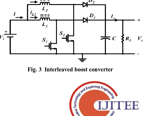
Interleaved boost converter
A basic boost convertor converts a DC voltage to a better DC voltage. Interleaving adds further benefits like reduced ripple currents in each the input and output circuits. Higher potency is complete by ripping the output current into 2 ways, well reducing I2R losses and electrical device AC losses. Figure one shows the fundamental interleaved boost topology. When s1 activates, current ramps up in L1 and slope reckoning on the input voltage, storing energy in L1. D1 is off throughout this point since the output voltage is bigger than the input voltage. Once s1 turns off, D1 conducts delivering a part of its keep energy to the load and therefore the output condenser. Current in L1 ramps down with a slope keen to the distinction between input and output voltage. One half a switching later, s2 conjointly activates finishing identical cycle of events. Since each power channels are combined at the output condenser, the effective ripple frequency is double that of a traditional single channel boost regulator.
[image:3.595.306.551.601.800.2]Maximum Power Extraction by using Converters for Hybrid Renewable Energy Source Fed Micro-Grid
The interleaved boost converter will increase the voltage output to the twice the amount from the input voltage. This unique quality makes this converter more efficient but it has its own draw backs as it has two semiconductor switches will increase semiconductor loss.
III. DESIGNING AND IMPLEMENTATION OF PROPOSED METHOD FOR MAXIMUM POWER EXTRACTION
This proposed maximum power extraction system consists of various elements to tune the system for better performance, those techniques which were explained above is implemented using MATLAB/Simulink simulation software which gives good platform for engineering projects to expand.
The total proposed system simulation model is shown in the figure 4. The power generated from solar and wind power is fed into interleaved boost converter and it is further sent to inverter circuit where the proposed PWM technique is used to give gate pulse to the semiconductor devices present in the circuit.
[image:4.595.85.519.238.396.2]The method used for improving the dc voltage from solar is MPPT controller. The solar simulation model is simulated as shown in the figure 5. It represents the dependable current source exited with a digital signal which is generated by mathematical model of solar power generation in Simulink.
Fig. 4 Simulation model for proposed hybrid wind solar generation system
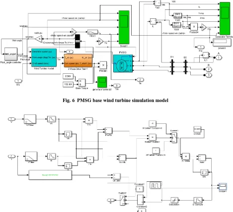
The wind power system consists of PMSG (permanent magnet synchronous generator) which is a synchronized steady output at variable input to get constant power output
the simulation model of proposed PMSG based wind turbine is presented in the simulation model as shown in the figure 6.
Fig. 5 Simulation model of solar power generation
The power generated by solar and wind power system is coupled to the interleaved boost converter which is controlled using a centralized FLC controller as shown in the figure 7.The simulation model is the MPPT with FLC implementation for the generation of pulse for boost converter.
[image:4.595.66.541.470.651.2]Fig. 6 PMSG base wind turbine simulation model
Fig. 7 simulation model of Proposed FLC controller for Boost Converter
This dc voltage is converted in to ac with the help of inverter circuit which is supported with the proposed PWM technique as shown in the figure 8.
Maximum Power Extraction by using Converters for Hybrid Renewable Energy Source Fed Micro-Grid
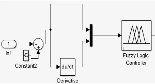
[image:6.595.47.296.122.258.2]The implemented FLC controller is shown in the simulation model of figure 9. It uses a Fuzzy interface system (FIS) to track the maximum power point there are two FIS were generally in use we use mamdani here for good speed of tracking the MPPT.
Fig. 9 Simulation model of Implemented Fuzzy Logic Controller
IV. SIMULATION RESULTS
The simulation is done through MATLAB software simulation tool it gives good platform for engineering design in mathematical form. Here we use Simulink tools for developing this project with good efficiency in developing.
The project is designed and simulation is compiles using MATLAB compiler and the output is made through scope.
Case 1: Hybrid with Battery Connected
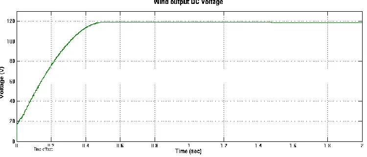
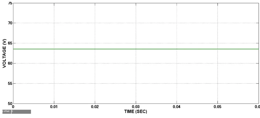
[image:6.595.98.512.523.694.2]The PV output voltage and wind output voltage is represented in the figure 10 and 12 respectively. It showed a constant output voltage due to the improved proposed MPPT technique. The solar power output is constant through MPPT controller at constant DC voltage of about 1.45 volt as shown in the figure.
Fig. 10 PV Output Voltage waveform
The wind power produces voltage of about120 volt which is converted into dc voltage output. The mppt technique
used which is triggered by FLC controller using mamdani technique.
Fig. 12 Wind System voltage waveform output
The pulse to the boost converer is shown in the figure 12.The voltage output from wind and solar is coupled using standard technique which can be boosted using interleaved boost converter the output of interleaved boost converter is
[image:7.595.75.538.295.470.2]increased due to the switching of IGBT semiconductor switches present in it.
Fig. 12 MPPT signal waveform for Interleaved Boost converter
The voltage generated by the hybrid system is low as it cannot be used for comersial or domestic purpose so the boost converter will boost it to desiered level the boosted
Maximum Power Extraction by using Converters for Hybrid Renewable Energy Source Fed Micro-Grid
Fig 13 Boost converter output Voltage waveform
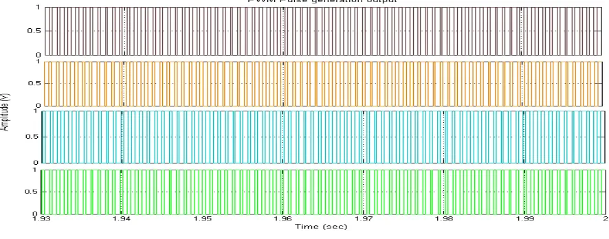
The steped up voltage is the fed into single phase inverter which is provided with the improvised pwm technique as shown in th figure 14. The four pwm signal is sent ot the
[image:8.595.78.521.336.510.2]semiconductor devices present in the inverter circuit in simulation model.
Fig. 14 PWM signal waveform for Inverter control
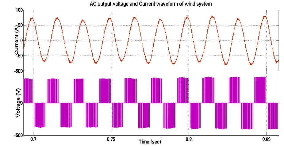
The final output AC voltage form inverter is generated and the voltage and current waveform is represented is as shown in the figure 15 and 16 respectively.
Generated output voltage waveform reaches to 600 volt AC output which is exactly the output voltage of DC voltage output referring that nil switching and conduction losses. The output current waveform rose to 100 amps due to the introduction of load consisting of resistive and reactive component.
Table. 1 Case 1 output parameters
CASE 1: Hybrid With battery connected
PV Voltage (V) 63.24
PV Current (A) 1.95
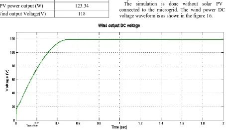
PV power output (W) 123.34
Wind output Voltage(V) 118
Wind output Current(A) 15
Wind Power Output(kW) 1.77
DC link voltage (V) 180
Boosted Voltage (V) 600
Output AC Voltage (V) 600
Output AC Current (A) 100
Output Power (kW) 60
Case 2: Wind power generation With Battery without PV power
The simulation is done without solar PV system connected to the microgrid. The wind power DC output voltage waveform is as shown in the figure 16.
Fig. 16 Wind power output voltage waveform
Wind power output current waveform is as shown in the figure 17.
Fig. 17 Wind output current waveform
[image:9.595.74.525.484.699.2]Maximum Power Extraction by using Converters for Hybrid Renewable Energy Source Fed Micro-Grid
Fig. 18 DC output boosted voltage waveform
The AC output voltage and current waveform is as shown in the figure 19.
.
Fig. 19 Output voltage waveform of AC
Table. 2 Case II Output Parameters Case 3: Solar with Battery Connected
[image:10.595.42.288.619.755.2]The solar PV voltage output waveform is as shown in the figure 20.
CaseII: Wind power generation
PV Voltage (V) 0
PV Current (A) 0
Wind output Voltage(V) 118
Wind output Current(A) 15
DC link voltage (V) 118
Boosted Voltage (V) 380
Output AC Voltage (V) 380
Fig. 20 solar PV voltage waveform
[image:11.595.76.519.264.430.2]The current output waveform for PV system due to battery is as shown in the figure 21.
Fig. 21 Solar PV output current waveform
The dc link voltage due to solar and battery connected is as shown in the figure 22.
Fig. 22 DC link voltage for PV with battery
[image:11.595.83.508.485.679.2]Maximum Power Extraction by using Converters for Hybrid Renewable Energy Source Fed Micro-Grid
Fig. 23 Boosted output voltage waveform
[image:12.595.63.527.303.540.2]AC output voltage and current output waveform is as shown in the figure 24 .
Fig. 24 Voltage and current output waveform for PV with Battery
The output is tabulated in table 3.
Table. 3 Case III Parameters
CaseIII: PV With battery connected
PV Voltage (V) 63.25
PV Current (A) 1.95
PV power (w) 123.34
Wind output Voltage(V) 0
Wind output Current(A) 0
DC link voltage (V) 63.25
Boosted Voltage (V) 200
Output AC Voltage (V) 200
Output AC Current (A) 40
Output Power (kW) 8
V. CONCLUSIONS
[image:12.595.55.284.606.755.2]The voltage gathered from wind and solar to be less as of 120 volt which is increased to about 400 volt as shown in the simulation diagram. This proposed method provides less ripple and harmonics which is also verified using the simulated proposed system. The scope of this project can also expanded to very lengthy extent as the application of renewable energy poses good innovative technology in upcoming days.
REFERENCES
1. Bakhshai et al., “A Hybrid Wind – Solar Energy System: A New Rectifier Stage Topology”, IEEE Magazine, July 2010.
2. R. Bharanikumar and A. Nirmal Kumar, “Analysis of Wind Turbine Driven PM Generator with Power Converters”, International Journal ofComputer and Electrical Engineering, Vol. 2 [4], August, 2010. 3. R. Billinton and R. Karki, “Capacity Expansion of Small Isolated
Power Systems Using PV and Wind Energy”, IEEE Transactions on PowerSystems,Vol. 16 [4], November 2001.
4. Chen et al., “Multi-Input Inverter for Grid-Connected Hybrid PV/Wind Power System”, IEEE Transactions on Power Electronics, vol. 22, May 2007.
5. D. C. Drago and G. Adrian, “Modeling of renewable hybrid energy sources”, Scientific Bulletin of the Petru Maior University of TirguMures, Vol. 6, 2009.
6. J. Hui, “An Adaptive Control Algorithm for Maximum Power Point Tracking for Wind Energy Conversion Systems”, Department of Electrical and Computer Engineering, Queen’s University, December 2008.
7. S. Jain and V. Agarwal, “An Integrated Hybrid Power Supply for Distributed Generation Applications Fed by Nonconventional Energy Sources”, IEEE Transactions on Energy Conversion, Vol. 22 [2], June 2008
8. N. Chayawatto, K. Kirtikara, V. Monyakul, C. Jivacate, and D.Chenvidhya, “DC–AC switching converter modeling’s of a PV grid-connected system under islanding phenomena,” Renewable Energy, vol. 34, pp. 2536-2544, Dec. 2009.
9. O.C. Onara, M. Uzunoglua, and M.S. Alam, “Dynamic modeling, design and simulation of a wind/fuel cell/ultra-capacitor-based hybrid power generation system, “Journal of Power Sources, vol. 161, pp. 707-722, Oct. 2006.
10.J.C.H. Phang, D.S.H. Chan, and J.R. Philips, “Accurate analytical method for the extraction of solar cell model parameter,” IEEE Electronics Letters, vol. 20, pp.406-408, May 1984.
11.M.G. Villalva, J.R. Gazoli, and E.R. Filho, “Comprehensive approach to modeling and simulation of photovoltaic arrays,” IEEE Transactions on Power Electronics, vol. 24, pp 1198 - 1208, May 2009.
12.H. De Battista, R.J. Mantz, F. Garelli, “Power conditioning for a wind-hydrogen energy system,” Journal of Power Sources, vol. 155, pp. 478-486, Apr. 2006.
13.E. Muljadi, C.P. Butterfield, “Pitch-controlled variable-speed wind turbine generation,” IEEE Trans. Industry Appl., vol. 37, pp. 240 246, Jan.-Feb. 2001.
14.Seul-Ki Kim, Jin-Hong Jeon, Chang-Hee Cho, Jong-Bo Ahn, and SaeHyuk Kwon, "Dynamic Modeling and Control of a Grid-Connected Hybrid Generation System With Versatile Power Transfer," IEEE Transactions On Industrial Electronics, Vo1.55, No.4, pp. 66-75, April 2008.
15.Mariusz Malinowski, Marian P. Kazmierkowski and Andrzej M. Trzynadlowski, "A Comparative Study of Control Techniques for PWM Rectifiers in AC Adjustable Speed Drives," IEEE Transactions On Power Electronic, Vol. 18, No. 6, November 2003.
16.Chih-Ming Hong, Chiung-Hsing Chen, "Intelligent control of a gridconnected wind-photovoltaic hybrid power," Electrical Power and Energy Systems, pp. 554-561,2014
17.Marian P. Kazmierkowski, and Luigi Malesani, "Current Control Techniques for Three-Phase Voltage-Source PWM Converters: A Survey," IEEE Transactionson Industrial Electronics, Vo1.45, No.5, pp. 691-70 I, October 1998.
18.Sergio Aurtenechea Larrinaga, Miguel Angel Rodriguez, "Productive Control Strategy for DC/AC Converters Based On Direct Power Control," IEEE Transactionson Industrial Electronics, Vo1.54, No.3, pp. 1261-1271, June 2007.