Abstract: Now-a-days most of the appliances and machine works on AC power. If AC power is unavailable for a short period of time, then during that period we need to supply AC power by converting the stored DC power. This can be possible using an Inverter. Inverters can be of multi-phase i.e. 3phase, 5phase, 6phase and so on. Since inverters have wide application in industries and HVDC transmission lines, the improvement in the output voltage and the reduction in harmonics are of utmost importance. In this paper a detailed analysis of harmonics and THD in a five phase inverter with different conduction angle along with the derived mathematical equations has been presented. A comparative study between three phase and five phase inverters at different conduction angle has been presented.
Keywords: Harmonics, Five Phase Inverter, Phase Voltage, THD
I. INTRODUCTION
Five phase inverters with ten switches are used in five phase VSI and CSI. This is the reason for which the improvement in the output voltage and the reduction in harmonics are of utmost importance. In five phase inverters, the conduction angle can change from 36o to 180o. The simulation model of a five phase voltage source inverter consists of five single phase bridge inverters connected in parallel. Depending on its application, the switches can be IGBT, MOSFET, GTO, etc. Each of the switches have diodes connected across them and these diodes act as feedback diodes which returns the energy stored in the inductive load to the dc supply. A comparative study on the total harmonic distortion of the output phase voltage at different conduction angle has been presented in this paper.
THD comparison for a three phase inverter at different conduction mode concludes that 150 deg conduction mode has least THD [1-2]. PWM operation of a five phase voltage source inverter with hysteresis controller can be applied to a variable speed induction motor drive under asymmetrical connections [3]. A comparative study of performance of five phase three level inverter with five phase two level inverter for equal loading shows that five phase three level gives better performance [4]. A five phase inverter fed five phase star connected load operating with five different excitations has been simulated and compared with that of three phase conventional inverter [5]. . The ripple in torque and harmonics can be reduced by supply a motor with multi phase supply that is greater than three phase supply [6]. A multiphase inverter with phase-shifted control is applied in electric vehicles for inductive power transfer [7]. Here the inverter phase angle is adjusted to regulate the charging voltage. The implementation of space vector pulse width
Revised Manuscript Received on November 05, 2019.
Byamakesh Nayak *, School of Electrical Engineering, KIIT University, Bhubaneswar, India. Email: electricbkn11@gmail.com
Sangeeta Sahu, School of Electrical Engineering, KIIT University, Bhubaneswar, India. Email: sahu.sangeeta@gmail.com
modulation for five phase inverter is very simplifies the computationally complexity [8-9]. Current imbalance between stator windings that results in shortening of the life of motor can be eliminated by symmetrical multiphase inverters [10].
II. STRUCTURE OF FIVE PHASE INVERTER The five phase inverter consists of five legs with two switches in each leg. Each switch has a diode connected in anti-parallel with it. The gating pulse in two adjacent switches has a delay of 720. The gate pulse between two switches of same leg is delayed by 1800. The five phase inverter is connected to a five phase star connected resistive load. Control signals at 1800 and 1440 are applied to the switches. The schematic diagram of five phase full bridge voltage source inverter is shown in fig.1
DC
a+
a-b+
b-c+
c-d+
d-e+
e-R
Fig.1. Schematic diagram of Five Phase Inverter In 180 deg mode of conduction, each switch conducts for 180 deg. At any particular instant, five switches are in ON state. Similarly in 144 deg mode of conduction, each switch conducts for 144 deg and at any particular instant, four switches are in ON state. The switching sequence for 180deg and 144 deg mode of conduction is shown in fig.2 and fig.3 respectively. Each of the five legs have switches a+ a-, b+ b-, c+ c-, d+ d- and e+ e- respectively. In 144 deg conduction, there is dead time of 36deg which is enough is avoid shoot through. In 180 deg conduction mode, at a time five switches are in ON state. After every 36 deg, one switch changes its state. In 144 deg conduction, at a time four switches are conducting and after every 36 deg, two switches are changing state.
Fig.2. Switching sequence diagram of five phase inverter at180deg conduction mode
Harmonics and THD in Five Phase Inverters
Fig.3. Switching sequence diagram of five phase inverter at144 deg conduction mode
III. OUTPUT VOLTAGE WAVEFORM OF FIVE
PHASE INVERTER
A. 180deg Conduction
[image:2.595.325.526.54.209.2]Fig.4 and 5 shows the phase voltage and line voltage waveform respectively of a 5phase VSI at 180 deg conduction mode.
[image:2.595.323.530.60.389.2]Fig.4. Phase voltage waveform of 5phase inverter at 180 deg conduction mode
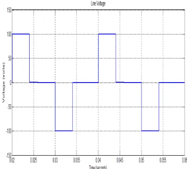
Fig.5. Line voltage waveform of 5phase inverter at 180 deg conduction mode
B. 144deg Conduction
Fig. 6 and 7 shows phase voltage and line voltage waveform respectively of a 5phase VSI at 144 deg conduction mode.
[image:2.595.320.534.227.398.2]Fig.6. Phase voltage waveform of 5phase inverter at 144 deg conduction mode
Fig.7. Line voltage waveform of 5phase inverter at 144 deg conduction mode
IV. MATHEMATICAL EQUATIONS OF FIVE PHASE
INVERTER
[image:2.595.67.264.286.455.2] [image:2.595.64.253.508.679.2]Table I. Mathematical Equations of three phase and five phase inverter.
Parameter
Three Phase Inverter Five Phase Inverter
180 deg 120 deg 180 deg 144 deg
bn 4 1 cos 3 3 dc V n n
2
cos
6
dcV
n
n
4 20.4 0.2 cos cos
5 5
dc
V n n
n
2
cos
10
dcV
n
n
Vphrms 4 1 cos 3 3 2 dc V n n 2 cos 6 dc V n n 1,3,5... 4 20.4 0.2 cos cos
5 5
2
dc
n
V n n
n
1,3,5... 2 cos 10 dc n V n n
Vphrms1 12
mV
VL1
2
V
phrms1
cos
30
2
V
phrms1
cos
54
THD
2 2
1
1
(
phrms phrms)
phrms
V
V
V
Power 23
V
phR
2
5
V
phR
V. RESULTS AND DISCUSSION
The phase voltage, line voltage, THD and loss comparison of three phase and five phase inverters at different conduction angles are shown in Table II. The table shows the simulation and the calculated values of various parameters of a five phase inverter. The phase voltage, line voltage and THD are calculated using the derived mathematical equations. The results are shown considering 1 p.u. input voltage. Here the switching loss, conduction loss and power handling capacity is considered as 1 for a three phase inverter. In a three phase inverter 180 deg conduction mode, three switches are in ON state at any instance. Thus conduction loss for three switches in one full cycle that is 360deg is considered as 1. Similarly every 60 deg interval, one switch is changing its state. Thus switching loss for assumed as 1 here. Accordingly the switching loss, conduction loss and power handling capacity of five phase inverter have been calculated in comparison to three phase inverter.
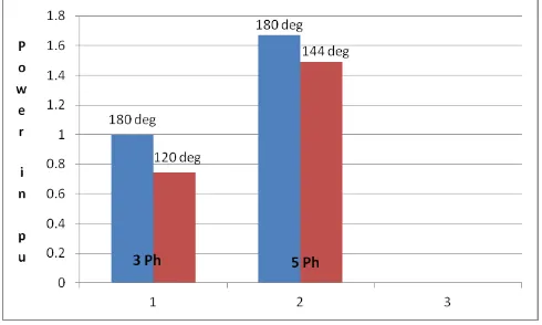
The magnitude of phase voltage of three phase and five phase inverters in 180deg conduction mode is same whereas it is different for any other conduction modes. Total Harmonic Distortion (THD) is less in five phase 144 deg conduction. Conduction loss in five phase at 144 deg conduction mode is less as compared to 180deg conduction mode whereas switching loss is more. The power handling capacity of five phase inverter is more than in three phase inverter. Fig 8 shows the power handling capacity of three phase and five phase inverters graphically at different conduction modes. From fig 9, it can be observed that magnitude of 3rd and 7th
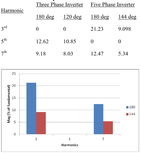
harmonic in a five phase inverter is less in 144 deg than in 180 deg conduction mode. Also, the fifth harmonic and its multiple are absent in a five phase inverter.
[image:3.595.304.549.486.633.2]Table. II. Comparison of three phase and five phase inverter at different conduction modes considering 1 p.u. input voltage
Parameter
Three Phase Inverter Five Phase Inverter
180 deg 120 deg 180 deg 144 deg
Sim. Result Sim. Result Sim. Result Cal. Result Sim. Result Cal. Result
Phase Voltage in volts 0.639 0.552 0.639 0.637 0.605 0.605
Line Voltage in volts 1.10 0.955 0.748 0.728 0.711 0.692
THD in Phase Voltage in % 30.9 30.9 42.93 43.14 30.19 29.87
THD in Line Voltage in % 30.9 30.9 65.45 65.23 42.93 42.912
V0rms1 0.45 0.389 0.45 0.45 0.43 0.43
V0rms 0.47 0.408 - 0.449 - 0.428
Switching Loss 1 2 - 1.67 - 3.33
Conduction Loss 1 0.67 - 1.67 - 1.33
[image:4.595.45.293.380.649.2]Power Handling Capacity 1 0.746 - 1.67 - 1.49
Table III. Harmonic Analysis of three phase and five phase inverter
Harmonic
Three Phase Inverter Five Phase Inverter
180 deg 120 deg 180 deg 144 deg
3rd 0 0 21.23 9.098
5th 12.62 10.85 0 0
7th 9.18 8.03 12.47 5.34
Fig.9. 3rd and 7th harmonic comparison of five phase inverter at 180 deg and 144 deg conduction mode
VI. CONCLUSION
After the harmonic and THD analysis, it can be concluded that the THD in a five phase inverter with 144 deg conduction is less than in a three phase inverter. The power handling capacity of a five phase inverter is more than a three phase inverter. The fifth order harmonics are absent in five phase inverter. The switching and conduction loss are more in a five
phase inverter due to more number of switches used. The output voltages, harmonics and THD has been calculated with the mentioned mathematical formulas. Also the calculated values of the output voltages, harmonics and THD approximately match with the results found from matlab simulink.
REFERENCES
1. Abhishek M. Patel, “THD Comparison for 180, 120 & 150 Degree Conduction Mode of Three Phase Inverter,” in International Journal for Scientific Research & Development, vol. 6, pp. 145 – 149, 2018 2. Jaimin Trivedi, Manori Shah, Jui Shah and Ruchit Soni, “Three Phase
150 Degree Mode of Conduction Voltage Source Inverter using Arduino,” International Journal of Engineering Research & Technology, vol. 5, pp. 272-275, 2016.
3. Hamid A. Toliyat, “Analysis and Simulation of Multi-Phase Variable Speed Induction Motor Drives Under Asymmetrical Connections,” in Proc. IEEE Applied Power Electronics Conf (APEC), 1996, vol. 2, pp. 586 – 592.
4. Bheemaiah Ch, Utkal Ranjan Muduli and Ranjan Kumar Behera, “Performance Comparison of Five-Phase Three-Level NPC to Five-Phase Two-Level Voltage Source Inverter,” IEEE International Conference on Power Electronics, Drives and Energy Systems, 2019. 5. M.A Inayathullaah and Dr. R. Anita, “Simulation of Five Phase Voltage
Source Inverter with Different Excitation for Star Connected Load,”
International Journal of Engineering and Technology, vol. 6, no. 3, 2014, pp. 1573 – 1580.
6. K. P. Prasad Rao, B. Krishna Veni and D. Ravithej, “Five-Leg Inverter for Five-Phase Supply,” International Journal of Engineering Trends and Technology, vol. 3, pp. 144 - 152, 2012.
7. Qijun Deng, Ziyi Wang, Cheng Chen, Dariusz Czarkowski, Marian K. Kazimierczuk, Hong Zhou , and Wenshan Hu, “Modeling and Control of Inductive Power Transfer System Supplied by Multiphase Phase-Controlled Inverter,” IEEE Trans. on Power Electronics, vol. 34, no. 9, pp. 9303 – 9315, 2019.
A uthor-1 Photo
9. Keng-Yuan Chen, “Space-vector pulse-width modulation for multiphase voltage source inverters considering reference order,” IET Power Electronics, vol. 9, pp. 81 – 94, 2016.
10. Zicheng Liu, Zedong Zheng, Lie Xu, Kui Wang and Yongdong Li, “Current Balance Control for Symmetrical Multiphase Inverters,” IEEE Trans. on Power Electronics, vol. 31, no. 6, pp. 4005 – 4012, 2016
AUTHORSPROFILE
She is born Odisha, India in April, 1981. She completed M.Tech in Electrical Engineering in the year 2015 from KIIT University, Bhubaneswar. She is a PhD scholar at KIIT University since 2017. Her main areas of research are Power Electronics and Electrical Drives and Electrical Machine. She has publications in IEEE Conferences and Scopus Indexed Journals.