International Journal of Innovative Technology and Exploring Engineering (IJITEE) ISSN: 2278-3075, Volume-8, Issue-11S, September 2019
Abstract- Production of conventional energy exhaust by every day, renewing to retrievable energy like wind energy, solar energy becomes necessity of the hours. The other reasons for the demand of solar energy are hazard free environment, Cary setup and low cost of maintenance during its operation and so on. A photovoltaic arrangement is used in solar energy system to convert heat and light energies to AC power with the help of inverter. In photovoltaic arrangement there are photovoltaic module, rechargeable battery, charge controller and inverter. Charge controller unit plays a significant role in this system to withstand battery charges for many hours and battery lifetime. This research provides the design of a solar energy controller for the battery charging unit with the function to connect and reconnect battery from the load during overcharging & discharging by using switches. A value added unit is available for power controlling, cutoff the power usage by the load and bypasses the solar energy to load with the help of electromagnetic-relays. Here the prototype system has been simulated for the 5 Volts battery and the same module has been implemented for 12 Volts battery.
Keywords: Solar energy, Power controller, Relay switch, Inverter, Photovoltaic panels.
I. INTRODUCTION
Sun light has heat and light energy, which provides reliable, pure and inexhaustible energy source. The influence of the solar energy which is considered one of the renewable energy exists in the earth. India comes under tropical regions, there by sunlight is at most of the time in the year. Hence solar energy can be a solution of the electrical energy. The solar energy system has also an added advantage, such as hazard free environment reasonable installation cost etc., solar energy power production, running cost can cut down the electricity consumption changes noticeably because, in a day with the help of solar energy domestic usage of electricity consumption for a house reduced by 50%. (Akarsh Sinha, et, al 2013) There are two types of generations through solar energy, one is photovoltaic process by converting heat energy into solar energy and other is solar thermal process, which converts heat energy into steam energy and then electrical energy.
Revised Manuscript Received on September 10, 2019.
S. Ramkumar, Asst. Prof. in Vel Tech Multi Tech Dr.Rangarajan Dr.Saguthala Engineering College, Chennai, Tamilnadu, India.
(Email: [email protected])
Vivekananda Reddy Vintha, Student of Jaya college of Engg. And Tech, Chennai, Tamilnadu, India.
(Email: [email protected])
M. Rathi, Kings Engg. College, Chennai, Tamilnadu, India. (Email: [email protected])
N. Padmaja, Asst. Prof. in Jaya college of Engg. And Tech, Chennai, Tamilnadu, India.
(Email: [email protected])
Photovoltaic (PV) is the direct process of converting solar energy into electricity. Photovoltaic power system is used in solar panels under solar electric modules or photovoltaic modules and it is made up of silicon solar cells. These silicon solar cells are connected in series in a flat arrangement and each panel can be accumulated with to a maximum number of 36 solar cells. In the module, cells can be arranged in series arrays or parallel arrays, which produce voltage and current. In this research, single panel or module and 12V battery. The photovoltaic system can be organized with serial or parallel arrays, which converts solar energy to electricity and array control system. (Michael M.D et, al 1998).
In Solar control unit that the charge controller is the main regulator to increase the lifetime of the battery. And power controller controls the power flow from inputs and outputs.
This research deals with solar energy using a solar panel with controller, which is converted into electricity the flow is measured by the charge controller and used to charge the batteries. There are two controllers are there, they are charge and power controllers. (Sarat Kumar Sahoo, et, at 2014)
(Enric , et, all 2013),A charge controller limits the rate at which that the electric current added or drawn from electric batteries. It prevents overcharging and over current which can reduce the performance and lifespan of a battery. It also prevents complete draining of a battery or performed controlled discharges, depends upon the battery technology. In power controller unit, controls the power consumption of load by AC supply and cutoff the mains supply then it converts solar energy to load. Power controller check the mains power supply, weather the supply is ON or OFF then it directs the solar power to battery. When the supply is OFF then it converts solar power to load. In power controller, there are three modes of operations, First condition, once battery charged up-to 100% then automatically solar energy shifts from battery to load directly. In second condition, the entire load current drawn from battery, which changes from power source in the absence of solar energy. In third condition, the load draws the supply only through solar energy.
Designing of Hybrid Automatic Solar Charging
System with Power Controller for Switching
Power Utilization..
II. GENERAL BLOCK DIAGRAM
Figure 1
These are the main components used in solar energy technology for standalone systems (Figure 1) and explained below:
1. Solar panels 2. Solar control unit 3. Inverter
4. Batteries
2.1 Solar Panels (Photovoltaic Conversion To Electrical Energy):
Photovoltaic source is the conversion of sunlight into electricity. Silicon material has been used in PV cell to create electric field between two doped elements. The two doped elements are considered as acceptor and donor. The p type doped material donor, the n type doped material is acceptor in the PV cell.
Once PV cell is exposed to sunlight, the photon in the light has some electrons which create electron-hole pair in the PV cell. Hence the electric field induced in the PV cell and consequences electrons moves from one to other side of the electrons.
2.2 Solar Control Unit:
In solar control unit, mainly charge and power controllers are used, in charge controllers that the overcharging controlled by Shottky diodes, IC used to compare voltages and amplify to pass different values to controller components . In power controller, it regulates different types of power inputs and outputs to charge the battery and conversion to load; in this mainly electromagnetic relays are used for switching conversion. MOSFET are used to convert DC signal to PWM signal.
2.3 Inverter:
An inverter basic function is to invert variable direct current output of the solar panels into alternating current. (Narendiran, et al 2013) DC is the power which flows in one direction in the circuit and helps in providing current when there is no electricity. Direct current is used for small applications. AC is the power that supplies back and forth inside the circuit. This inverter also used to charge the battery and when the solar irradiance inefficient from solar panels, it senses through different circuits in power controller. By bypassing the both inputs and outputs to the SCU (solar control unit), it controls different functions running through the inverter.
2.4 Batteries:
A rechargeable battery is an energy storage device that can be charged again and again after being discharged by applying dc current to terminals. There are two different connections of batteries, series and parallel, in series connection that the voltage divides and not constant and in parallel that the voltage does not divides and constant. When the battery connected in series, one battery may not damage other batteries but parallel connections entire batteries may be damaged. (Ross, J.et, al 2007)
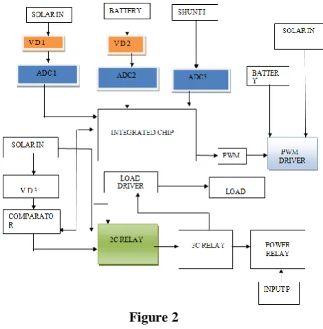
III. BLOCK DIAGRAM OF SCU:
The given block diagram (Figure 2) explains the overall functions and operations of a solar control unit, mainly integrated chip controls the power flow in the circuit and electromagnetic switching relays switches the power mode, solar mode and automatic converting operations in the device. (Dunlop. et, al 2013)
Figure 2
3.1 Integrated Chip:
LM324N is an integrated circuit, which is used to compare the voltage and current levels in different part of the circuits. This chip compares the input and output values and compared values circulated internally.
3.2 A-D-Converter:
An analog digital converter is widely used electronic component that converts an analog electrical signal into a digital representation. When input signals are given with voltages and currents then it converts that signals into digitally and sends information to particular component then it differs with others signal.
3.3 Comparator And Voltage Dividers:
International Journal of Innovative Technology and Exploring Engineering (IJITEE) ISSN: 2278-3075, Volume-8, Issue-11S, September 2019
voltage. Voltage division is the result of input voltage among the components of the divider and resistance voltage dividers are used for the reference voltages and to reduce the magnitude of the voltages.
3.4 Relays:
A relay is also known as switching device. An electromagnetic relays which operates as a magnetic relay,
After fixing the reference value, when it exceeds it value then the relay act and switches to one circuit to other. Electromagnetic relays are used in ac and dc combination switches.
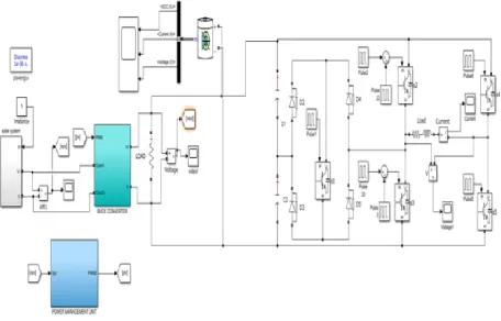
[image:3.595.64.521.145.437.2]IV. SIMULATION DIAGRAM
Figure 3
This is the basic simulation model (Figure 3) for 5v battery and there are different sections and components are used to understand the logical operations in this simulink: (Akarsh Sinha, et, al 2013)
1. Solar irradiance circuit 2. Power management circuit 3. Buck converter
4. Switching devices
4.1 Solar Irradiance:
In this circuit, that the irradiance given to the diode to enhance the negative voltage to the battery and there is a basic circuit design in connecting solar panel to input voltage supply and this is given in figure 4.
Figure 4
4.2 Power Management:
In power management, that the input power to passing to battery, when the solar irradiance inefficient in sunny days .So, inverter is used to convert AC to DC to charge the battery and as well as to convert DC to AC to run load (Figure 5).
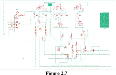
V.SCHEMATIC DIAGRAM
Figure 2.6
The above figure 2.6 is a charge controller circuit, this circuit which supports to the discharging the overvoltage and reverse current are controlled. From the above circuit diagram, that the cutoff voltage were set to withstand the battery for many cycles, by connecting variable resistance through the transistor then voltage to be forward biased after the biasing that the base voltage configuration to be applied to relay circuit then diverts the circuit from battery connection circuit to load shown in Figure 2.7.
Figure 2.7
VI. SCHEMATIC DIAGRAM OF POWER CONTROLLER CIRCUIT
In power controller circuit, switching to power mode and solar modes, and when the battery charged up by 14v then by the reference value of the potentiometer sense it and electromagnetic relay directs the solar mode to load.
VII. RESULTS AND DISCUSSION:
• In battery overcharging circuit, once the threshold voltage 11.5V reached in potentiometer, then forward voltage in transistor flows through base collector configuration, with the help of electromagnetic relay, it shifts battery circuit to load circuit.
• In solar mode, that the 2C relay is connected to input supply mode, when the power mode is in off condition.
• In power mode, both 2C and 3C relays are activated, by checking the reference voltage from the solar energy, if it insufficient to generate DC power, then mains power activated.
• In low battery sensing unit, reference voltage given as 1.0V, then the forward voltage from the input passed to
the Zener diode to sense the voltage whether <1.0V then indicator indicated with LED
7.1. Voltage Regulation Set Point:
In this mode whenever the battery voltage is increase over the voltage regulation set point at some specific current then battery will disconnect from the PV system. In simulation the green Led is used to indicate the battery charging and fully charged condition. Here the green Led is switch off as the battery voltage is higher than VR set point. That means the battery is fully charged. Up to this VR set-point the battery will charging.
7.2 Array Reconnect Voltage:
In this mode whenever the battery voltage is decrease lower than Array Reconnect Voltage (ARV) at some specific current then battery will reconnect with the PV system. In simulation the green Led is used to indicate the battery charging and fully charged condition. Here the green Led is switch on as the battery voltage is lower than ARV set point. That means the battery is start charging. Up to this VR set-point the battery will charging.
7.3 Low Voltage Disconnect
In this mode whenever the battery voltage is decrease lower than Array Low Voltage Disconnect (LVD) at some specific current then Load will disconnect from the battery. In simulation a white Led is used to indicate the load connecting and disconnecting condition. Here the Led is switch off as the battery voltage is lower than LVD set-point. That means the Load is disconnecting from battery to protect the battery from over discharge.
VIII. SIMULATION OUTPUT
Table 1
IX. PROTOTYPE OUTPUT
Table 3
X. CONCLUSION
The outcome of the research, carried out in this paper for designing of solar charging controller & power controller for switching power system. This is a navel approach to reduce the power consumption & increases the usage of renewable energy.
[image:4.595.66.287.53.209.2] [image:4.595.60.294.342.493.2]International Journal of Innovative Technology and Exploring Engineering (IJITEE) ISSN: 2278-3075, Volume-8, Issue-11S, September 2019
domestic usage by converting directly from solar energy & coupling both mains source and solar energy & also reciprocally it changes the battery of the inverter. Based on the above type a prototype has been formed, once threshold voltage 11.5 reached in the potentiometer with the help of the transistor then the switching occurs between battery and load. The entire process carried out through relay circuit thereby power consumption noticeably increases.
XI. REFERENCES
1. Dunlop, "Batteries and Charge Control in Stand-alone
Photovoltaic Systems. Fundamentals and Application",
Working Paper, Sandia National Laboratories,
Photovoltaic Systems Applications Dept., Florida Solar Energy Center, Cocoa/Florida -. USA, 1997
2. Ross, J., Markvart, T., and He, W.: Modelling Battery
Charge Regulation for a Stand-alone Photovoltaic System, Sol. Energy, 2000, 69, (3), pp. 181- 190
3. Enric, P.U and Michael M.D (1998): Recommended
Practices for Charge Controllers. Renewable Energy and Hybrid System Group CANMEI Energy Diversification
Research Laboratory.M.K.A1am, F.H.Khan and
A.S.Imtiaz, "An efficient power electronics solution for lateral multi-junction solar cell systems," in Proc.IEEE IECON, pp.4373-4378, 2011.
4. Sarat Kuma Sahoo, G. Iulasi Ram Das, Vedam
Subrahmanyam "Contribution of FPGAs to Industrial Drives A Review," International Conference on information and Communication technology in Electrical Sciences, Pp.343-348, 2007.
5. Akarsh Sinha, M. Pavithra, K.R. Sutharshan, Sarat
Kumar Sahoo, "Arduino Based Pulse Width Modulated Output Voltage Control of a dc-dc Boost Converter Using Proportional, Integral and Derivative Control Strategy," Australian Journal of Basic and Applied Sciences, vol.7, nO.ll, pp.l04-108, Sept 2013.
6. S.Narendiran, S.K.Sahoo "Grid Connected Photovoltaic
Energy conversion system-A case study," International conference on power, Energy and control, pp.23-25, 2013.
7. S.Narendiran, Sarat Kumar Sahoo, "Modelling and
Simulation of Solar Photovoltaic Cell for Different
Insolation Values Based on MAILAB/Simulink
Environment," International Journal of Applied
Mechanics And Materials, vol. 550, pp.137-143, 2014.
8. S.Narendiran, Mayur Bansal, Sarat Kumar Sahoo,