International Journal of Innovative Technology and Exploring Engineering (IJITEE) ISSN: 2278-3075, Volume-9 Issue-2, December 2019
Abstract: The work focuses upon design of minimum length supersonic nozzle, using the method of characteristics, for the given combustion chamber conditions, which are going to serve as nozzle inlet conditions. It is assumed that the flow has somehow been accelerated to the sonic value through a suitable convergent nozzle and from that point; the divergent portion of the nozzle is to be designed using the method of characteristics. The optimum exit area and hence, the Mach number are predicted and this Mach number is the value for which the nozzle has to be designed. The results obtained are validated with the results obtained by validation in ANSYS and based on the observation, followed by a discussion on the optimisation of results.
Keywords:Method of characteristics, Prandtl - Meyer function, expansion fans.
I.INTRODUCTION
A nozzle is a device designed to control the characteristics like pressure, velocity, density etc., of a fluid flow (especially to increase velocity). A nozzle is often a pipe or tube of varying cross sectional area and it can be used to direct or modify the flow of a fluid. Nozzles are frequently used to control the rate of flow, speed, direction, mass, shape, and or the pressure of the stream that emerges from them. A de Laval nozzle (or convergent-divergent nozzle, CD nozzle) is a nozzle, that has minimum cross sectional area somewhere in between the inlet and the exit, making a carefully balanced, asymmetric hourglass-shape. It was developed by Swedish inventor Gustaf de Laval in 1888 for use on a steam turbine. This principle was first used in a rocket engine by Robert Goddard. Very nearly all modern rocket engines that employ hot gas combustion use de Laval nozzles.
A.OPERATION OF A CD NOZZLE
For a fluid moving through a converging duct, the cross section area should be decreased to increase the velocity by accelerating the flow.
Revised Manuscript Received on December 05, 2019.
Nirmith Kumar Mishra, Department of Aeronautical Engineering,
MLR Institute of Technology, Email: [email protected]
A.Sai Kumar, Department of Aeronautical Engineering, MLR Institute
of Technology, Email: [email protected]
M.Ganesh, Department of Aeronautical Engineering, MLR Institute of
Technology, Email: [email protected]
Mohd Abdul Rehman Alam, Department of Aeronautical
Engineering, MLR Institute of Technology, [email protected]
This is as suggested by the simple continuity equation that the mass flow through any cross section per unit time (which is a product of area, density and velocity) is a constant value. This means that the velocity and the area are inversely proportional. So to accelerate the flow, the area has to be reduced. But this is only in the subsonic regime of the flow. At the throat, the flow acquires maximum velocity possible through converging duct, which is the local sonic velocity at the narrowest region called the throat. This condition of flow, having local sonic velocity, leads to maximum mass flow rate possible through given throat area, for given inlet and exit conditions. This is known as choking. Once the flow is just choked, it is an unsteady condition. Any increase in the back pressure or decrease in the inlet pressure causes the flow to decelerate in the divergent section, while any decrease in the back pressure or increase in the inlet pressure causes the flow to accelerate to supersonic regime, with an increase in area in the divergent section.
B. NOZZLE EXIT CONDITIONS
[image:1.595.328.522.582.728.2]The flow occurs in such a way, that it always tries to match its static pressure at the nozzle exit with the atmospheric static pressure. Now when this doesn‟t happen, the nature sets up its own ways through shocks and expansion fans. When the exit static pressure is more than the atmospheric pressure, the flow is still to be expanded to match its static pressure to the atmospheric pressure, which is achieved by expansion fan formation. This condition is called the under expanded condition. When the exit static pressure is less than the atmospheric pressure, the flow has expanded more than it should and its static pressure should be increased to match the atmospheric pressure, which is achieved by normal shock formation. This condition is called the under expanded condition.
Figure 1.1: Shock travelling in a c-d nozzle Therefore, the shock starts at the nozzle throat and thereon traverses along the flow downstream.
When the shock sits near the throat, it is called the first
Design of Minimum Length Supersonic Nozzle
using the Method of Characteristics
critical point. When travelling along downstream it sits at the nozzle exit, it is called the second critical point and the initial condition of shock free nozzle corresponds to third critical point.
Figure 1.2: flow through a C-D nozzle
C. MINIMUM LENGTH NOZZLE
[image:2.595.66.272.100.254.2]A part of the rocket‟s thrust has to overcome rocket‟s weight. This makes it desirable to have minimum weight hence, minimum length. This is possible by making the smooth curvature of the throat, shrink to a point. This creates an expansion fan at the expansion corner instead of a smooth expansion, spread over the curved throat. This leads to the shrinking of the nozzle length that is required for expanding the flow to the desired Mach number.
Figure 1.3: Minimum length and gradual expansion nozzle
D.DRAWBACK OF HAVING MINIMUM LENGTH
Due to the sudden and jerky expansion in the minimum length nozzle throat, the flow near the throat region of a minimum length nozzle is not as smooth as that in the gradual expansion nozzle. This suggests that there is a pressure loss in that region.
ASSUMPTIONS
1.The gas is assumed to be an ideal gas.
2.Flow is steady, uniform, irrotational, inviscid, laminar and isentropic.
3.The total pressure and total temperature at the combustion chamber exit can be uniquely determined.
II.METHODOLOGY
A.THE METHOD OF CHARACTERISTICS
Method of characteristics is basically a mathematical method, used to reduce a nonlinear coupled partial differential equation into simpler, decoupled equations along specific directions known as the characteristics directions. In the problems involving supersonic flows, the combination of mass, momentum and energy conservation, gives such a
nonlinear, partial, coupled differential equation. Decoupling that equation involves making the term having coupled variables indeterminate. This gives two sets of equations, one corresponding to the direction of the characteristic curves and the other representing the compatibility conditions.
Directions of characteristics
…1
Compatibility conditions
...2
The above two equations are instrumental in building up the characteristic fibre for the domain of interest in the flow field.
B. SUPERSONIC NOZZLE DESIGN
One of the important applications of method of characteristics is supersonic nozzle design. This involves the implementation of bits of the design process known as sub routines, starting from an initial condition.
Subroutines
A point in the flow field is recognised in terms of the corresponding to that point. Subroutines
are used to find the properties at third point, when two points are known. Now depending upon the location of the third point, there are various subroutines of which, a suitable one is employed to find the third point.
C. INTERIOR POINT SUBROUTINE
This is employed for a point, well inside the flow.
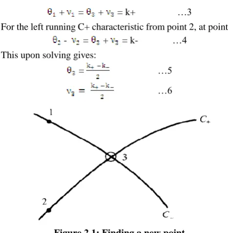
For the right running C- characteristic from point 1, at point 3:
+ = + = k+ …3
For the left running C+ characteristic from point 2, at point 3: - = + = k- …4
This upon solving gives:
= …5
[image:2.595.304.538.433.672.2]…6
Figure 2.1: Finding a new point
As is known, the Mach number M is calculated at point 3 using the Prandtl Meyer relation (usage of the Newton-Raphson scheme is recommended in doing this). From the Mach number, the Mach angle is calculated using the relation
…7
International Journal of Innovative Technology and Exploring Engineering (IJITEE) ISSN: 2278-3075, Volume-9 Issue-2, December 2019
calculated by using the equation (1). Wall point subroutine
This is a special case of the interior point subroutine, where the condition is , rest of the routine being the same. Axis point subroutine
This is also a special case of the interior point subroutine, where the condition is
Since the axis makes an angle of zero degrees with the reference.
Other subroutines are exterior point subroutine and shock point subroutines, which aren‟t used in the current work and are kept out of discussion.
D. DECIDING THE OPTIMAL EXIT MACH NUMBER FOR GIVEN COMBUSTION CHAMBER CONDITIONS
Throat dimensions are a priory known. The throat height is incremented little by little. Corresponding area is then calculated .Then corresponding Mach number is also calculated using the area ratio, through Newton-Raphson method. Corresponding static pressure and static temperature is then calculated using isentropic relations. Then velocity, density and mass flow rate corresponding to area at hand are calculated. Thrust corresponding to that area is calculated using the above data. The static pressure is checked if it is less than the atmospheric pressure. If this condition is met, the loop is broken and the corresponding Mach number is set as the exit Mach number. Otherwise, the loop continues to execute, till the condition is met.
E. Validation through ANSYS
The coordinates were imported from MATLAB into ANSYS and the geometry was made. The pressure inlet and pressure outlet conditions were given to the inlet and exit respectively. „No slip‟ condition was given to the nozzle wall and the symmetry condition was given for the axis, to consider the other half of the nozzle contour.
III.RESULTS
[image:3.595.318.532.477.617.2]A. FROM PROGRAM
Figure 3.1: nozzle contour; Mach no. and p/pc v/s nozzle length
Mach number changes from M* = 1 at the throat to M_exit = 3.8759 at the exit. Static pressure also changes from P* =
1.1099e+07 at the throat to P_exit = 5.7596e+06 at the exit, while the total pressure is kept constant in the code (isentropic assumption)
The nozzle coordinates were obtained from the code.
Figure 3.2: Points for upper contour of the 2-d nozzle
B. FROM ANSYS
The above obtained points were then used to design the nozzle 2-D geometry in the ANSYS.
Figure 3.3: nozzle contour obtained from the points
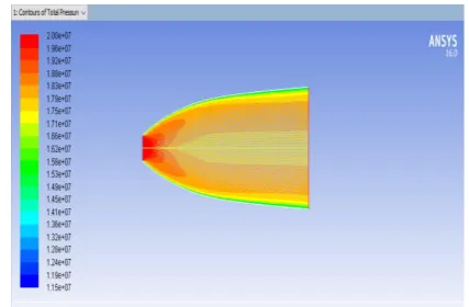
Figure 3.4: variation of total pressure
The total pressure is observed to decrease along the nozzle length and also a much more decrease is found near the nozzle wall. This is because the „No-Slip‟ condition at the nozzle wall, which is an approximation to the real case, has led to the boundary layer formation and hence, the total pressure loss.
[image:3.595.60.265.541.722.2]constant in the code, assuming the flow to be isentropic, which is more of an ideal time approximation.
Figure 3.5: variation of static pressure
[image:4.595.63.278.76.219.2]As the Mach number increases with the increasing area, the static pressure drops along the nozzle length. This drop continues till the nozzle exit, where the static pressure roughly matches the atmospheric pressure.
Figure 3.6: variation of static temperature
[image:4.595.61.273.290.425.2]The gas in the analysis is considered to be an ideal gas, which obeys the ideal gas law P = ρRT. The relation suggests that static pressure is directly proportional to the static temperature. As the static pressure decreases along the nozzle exit, so should the static temperature do, being a directly proportional quantity. This can be clearly seen in the above figure. The static temperature change is more sensitive to the change in Mach number than the velocity. It decreases along the downstream of nozzle; however, the total temperature remains constant as the process is adiabatic.
Figure 3.7: variation of total temperature As the process is adiabatic, there should be no loss in the total enthalpy, hence in the total temperature. It can be seen that the above figure is in well agreement with the fact.
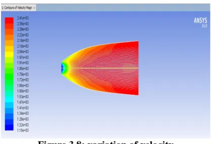
Figure 3.8: variation of velocity
It was observed that the static pressure was decreasing along the nozzle length, which clearly means that the velocity should increase. This mutual agreement of the pressure and the velocity can be seen from the above contour.
IV.CONCLUSION
The minimum length supersonic nozzle has been generated through code and has been analyzed in the ANSYS for various aspects and the results have been compared. The exit Mach number evaluated from the code is 3.8759 and the Mach number obtained from the ANSYS is about 3.4. This is because the code doesn‟t take into account, the non-isentropic nature of the flow but the ANSYS considers the assumption, leading to loss in the total pressure due to „no-slip‟ condition. This means, the nozzle when designed and actually put to test in reality, gives the exit Mach number somewhere between 3.4 and 3.8759. This is because, in reality, the flow is neither isentropic, nor will the „no-slip‟ condition is perfectly obeyed. The real process occurs somewhere between the two.
V. FUTURE SCOPE
In the current work, the nozzle is designed using the code, which considers the flow to be isentropic. But in reality, the flow is not isentropic. This affects the code‟s accuracy, as it doesn‟t account for the pressure loss and gives a higher Mach number than that would be achieved in reality using the same nozzle.
This loss can be reduced, by considering the total pressure loss occurred in the flow field. This is to be done using the Fanno flow theory (as the pressure loss is majorly due to the wall friction). This immediately puts forth an obstacle that the Fanno flow theory is generally used while dealing with a constant area duct.
One idea to implement the Fanno flow theory in a variable area duct is to approximate the duct of continuously varying area into duct of a large number of ducts, each of a constant area and apply the Fanno flow theory to calculate the pressure loss in each duct of a very small length and add all the total pressure loss accounted by each discrete duct. Finally, this total pressure loss is to be subtracted from the actual total pressure that was assumed in the isentropic flow.
This shall give the exit conditions, by accounting for the total pressure loss, which in turn
[image:4.595.63.274.555.688.2]International Journal of Innovative Technology and Exploring Engineering (IJITEE) ISSN: 2278-3075, Volume-9 Issue-2, December 2019
to
accurate and compatible with the real conditions.
REFERENCES
1. Brandon Lee Denton,(2008), “Design and Analysis of Rocket Nozzle
Contours for Launching Pico-Satellites” RIT Scholar Works
2. Ayub Padania, Sanjay Kumar Sardiwal, D. Harika Chowdary, Md.
Abdul Toufeeq (2014), “Aerodynamic Design and Simulation of Annular Nozzle Using Method of Characteristics”, International Journal of Engineering Sciences & Management, ISSN: 2277-5528
3. Srinivas G, Bhupal Rakham, (2017) “Experimental and numerical
analysis of convergent nozzle”, IOP Conf. Ser.: Mater. Sci. Eng. 197 012081
4. Athota Rathan Babu, Shiva Prasad U, B Praveen, Suresh Kumar R, GSD
Madhav (2017) “Nozzle Contour Design For Space Propulsion Module”, International Journal of Mechanical and Production Engineering Research and Development (IJMPERD), ISSN (P): 2249-6890; ISSN (E): 2249-8001 Vol. 7, Issue 4, Aug 2017, 351-360
5. Vadla Phaneendra, S Sreekanth (2018) “Turbo jet engine nozzle design
optimization to reduce noise”, IOP Conf. Ser.: Mater. Sci. Eng. 455 012043
6. Anderson JD, 2001, “Fundamentals of Aerodynamics”, 3rd Edition, pp.
532-537, pp.555-585.
7. Anderson JD, 1982, “Modern Compressible Flow with Historical
Perspective”, pp. 268- 270, pp. 282-286.
8. Shapiro AH, 1953, “The Dynamics and Thermodynamics of
Compressible Fluid Flow”, Vol. I, pp. 294-295.
9. Shapiro AH, 1954, “The Dynamics and Thermodynamics of
Compressible Fluid Flow”, Vol. II, pp. 694-695.
10. Sutton, GP, “Rocket Propulsion Elements”, 7th Edition
AUTHORS PROFILE
Nirmith Kumar Mishra Assistant Professor,
Department of Aeronautical Engineering, MLR
Institute of Technology, Hyderabad and he is also Associate Member of Aeronautical Society of India & Member of SAE India
A.Sai Kumar Assistant Professor, Department of
Aeronautical Engineering, MLR Institute of
Technology, Hyderabad & Research Scholar at Osmania University and he is Professional member of SAE India & Associate Member of IAAA.
M.Ganesh Associate Professor, Department of
Aeronautical Engineering,MLR Institute of Technology,
Hyderabad & Research Scholar at KL University and he is also Professional member of SAE India & Associate Member of IAAA.
Mohd Abdul Rehman Alam, Student, Department of
Aeronautical Engineering,MLR Institute of Technology,