Abstract: The risk of Subsynchronous Resonance (SSR) may reduce with the hybrid of active and passive series compensations. The hybrid series compensation can be done with Static Synchronous Series Compensator (SSSC) (an active FACTS device) and fixed series capacitor (passive compensation). In this paper, we propose a Band Pass Filter (BPF) based Subsynchronous Damping Controller (SSDC) with SSSC. The aim of the paper is to increase the damping of all critical TMs with minimum number of highly frequency selective BPFs. The BPFs are used to extract the subsynchronous frequency components from electrical network. The extracted subsynchronous frequency components are used to modulate the reference value of SSSC injected voltage. Thereby, the SSSC injecting voltage can suppress the subsynchronous currents flowing in the transmission network. The linear (DQ) model is developed in MATLAB-Simulink using the differential and algebraic equations of the system. The damping torque, eigenvalue and transient simulation methods are performed with the linear model to carry out the analysis of SSR. The eigenvalue analysis is used to select the number of filters. The number of BPFs is selected in view of suppressing the torsional vibrations at all critical frequencies. The outcomes of the paper show that the negative damping is considerably diminished with the proposed SSDC in the entire range of torsional mode frequencies and mitigate SSR.
Keywords: Damping torque, eigenvalue, static synchronous series compensator, subsynchronous resonance, subsynchronous damping controller, voltage source converter, Band pass filter.
I. INTRODUCTION
T
he huge rise in demand for electrical power imposes the transmission lines to transmit bulk power. The series and shunt compensation using capacitors are the economic solutions to increase the transmission capability of long power lines, the stability of the system, as well as voltage regulation [1]–[3]. There occurs a potential SSR problem due to the series compensation of long line connected to turbine-generator [4], [5]. The previous research has proposed various SSDCs with FACTS devices, which are intended to boost the stability as well as voltage regulation and to mitigate the SSR. In [6]–[8], SSSC using Low Pass Filter (LPF) is reported to mitigate SSR. The SSDC with SSSC based on Transfer Function (TF) is discussed in [9], which is used to mitigate SSR by decreasing the electricalRevised Manuscript Received on December 05, 2019.
* Correspondence Author
S. Venkateswarlu, School of Electrical Engineering, Research Scholar, Vellore Institute of Technology, Vellore, India. Email: [email protected]
M. Janaki*, School of Electrical Engineering, Associate Professor, Vellore Institute of Technology, Vellore, India. Email: [email protected]
resonant frequency. In [10], SSDC using gain/phase compensation is reported to damp the subsynchronous oscillations. The improved Blocking Filter (BF) is used to mitigate the various SSR problems in the Tuoketuo power system, and the family of Subsynchronous Dampers (SSDs) based SSDC is reported to damp the multi-modal SSR [11].
Our previous works report BPF and Kalman Filter (KF) based SSDC respectively, which significantly diminish the negative damping in the practical range of series compensation [12].
The aim of this paper is to enhance the damping of all critical torsional modes (TM) with minimum number of highly frequency selective BPFs. We present the analysis and simulation of SSR with passive series compensation and active compensation using SSSC. The SSR analysis is carried out on the modified IEEE First Benchmark Model (FBM) with SSSC and BPF based SSDC [12]. The damping torque, eigenvalue and transient simulation methods are performed with the linear model to analyze SSR. BPF based SSDC is designed on the basis of TM frequencies and damping torque. The number of BPFs is selected from the eigenvalue analysis. The estimated subsynchronous frequency components (output of BPF based SSDC) are used to modulate the reference value of SSSC injected voltage. Thereby, the SSSC can inject voltages in the transmission line to suppress the subsynchronous currents flowing to the generator. The performance of the BPF based SSDC with SSSC is validated through the damping torque, eigenvalue analysis and transient simulation under large disturbance. The results show that, in the entire range of TM frequencies the peak value of negative damping considerably decreases with proposed SSDC and mitigate the SSR.
The sections of this paper are organized as follows. The methods to analyze SSR is detailed in Section II. The system description and SSR analysis with SSSC are discussed in Section III. The design of BPF based SSDC is described in Section IV. The SSR with SSSC and BPF based SSDC is analyzed in Section V. The discussion on results and conclusions are presented in Section VI and Section VII, respectively.
II. METHODSTOANALYZESSR
The methods of SSR analysis are presented in the following subsections [3], [12].
A. Damping Torque Analysis
The dynamics of the mechanical system are neglected in the damping torque analysis.
BPF based Estimation and Mitigation of SSR
with SSSC
From Fig.1, the damping torque is given as [3] 1 )] ( [ ) ( ) ( ) ( k m e
de H j
j S j T T
(1)
The generator rotor speed is denoted by Smp.u and the
[image:2.595.302.549.55.206.2]electrical torque is denoted by Te p.u.
Fig. 1.Interaction between mechanical and electrical system [12].
The electrical damping torque (Tde)is calculated from the
generator internal bus and it is given by [13]
2 0
* )
( Y E
j Y
Tde QD QQ
(2)
where Tde is the electrical damping torque
QD
Y
andY
QQare the admittance functions in DQ frame0
is the operating frequency and E is the generator internal bus voltage.At any frequency, if the damping torque is negative and if that particular frequency is matching with any of the TM frequency, then the corresponding TM may be unstable.
B. Eigenvalue Analysis
The eigenvalue analysis is carried out with a detailed model of both electrical and mechanical systems. The linear DQ model is developed in Matlab-Simulink using the system differential and algebraic equations. The state matrix is obtained to compute the eigenvalues. The sign of the real part of eigenvalues indicates either system is stable or unstable. The system is said to be unstable if any one of the eigenvalues has a negative real part [12].
C. Transient Simulation
The outcomes of damping torque and eigenvalue analysis are validated by time-domain simulation of the system with large disturbances. The linear DQ model is used to perform the analysis of transient SSR for the step disturbance at an operating point. The transient stability is assessed from the time response. In order to see the transient response, 10% fall in mechanical torque is initiated and removed at 0.5 sec and 1.0 sec respectively. The system is transiently stable if the oscillatory response decreases with time.
III. SYSTEMDESCRIPTIONANDANALYSISOF SSRWITHSSSC
A. System Description
The study system is adapted from IEEE FBM with the inclusion of SSSC [12]. The diagram of study system is shown in Fig. 2. The information of the electromechanical system are referred in [3], [14].
Fig. 2.Modified IEEE FBM with SSSC [12]. The damping torque analysis is executed with generator classical model. The state model of the network is derived from the generator terminal to infinite bus and it is given by [3] b i Q i D CQ CD q d b e q d e e b e b e q d E E E V V dt didt di X i i R X X R V V 1 0 cos sin sin cos (3) where d i , q i and
d V ,
q
V are the dq components of the line current and generator terminal voltage with respect to the machine reference frame.
e
X and Rerepresent the equivalent reactance and equivalent resistance viewed from the generator terminal.
b
is the generator rotor speed in p.u.
is the generator rotor angle.
CD V and
CQ
V are the capacitor voltage DQ variables.
i D
E and i Q
E are the DQ components of the SSSC injected voltage.
b
E is the infinite bus voltage.
(1) Modeling of SSSC in D-Q reference frame
Fig. 3 and Fig. 4 show the schematic diagram and equivalent circuit of SSSC respectively [3], [12]. SSSC comprises a coupling transformer, Voltage Source Converter (VSC) and the DC link capacitor as shown in Fig. 3.
The DQ components of the injected voltage Ei are
represented by i D
E and i Q
E respectively and are defined as
follows:
) sin(
k dc
i
D M V
E (4)
) cos(
k dc
i
Q M V
E (5) The magnitude of the output voltage at ac side of the converter in DQ reference frame is given by
dc k i Q i D
i E E M V
E 2 2 (6)
where
M
kis the modulation index and is given asse k p
[image:2.595.64.273.130.216.2]where
6
4
p
for a 24-pulse converter.is the transformation ratio of SSSC interfacing transformer.
se
is the dead angle.
dc
[image:3.595.310.544.54.144.2]V is the dc capacitor voltage.
Fig. 3. Schematic diagram of SSSC [12], [15].
Fig. 4. SSSC equivalent circuit [12].
In the control perspective, it is convenient to represent the real voltage (Ep) and reactive voltage ( )
R
E as components
of converter voltage(Ei). The real voltage (Ep) being in
phase and the reactive voltage (ER) is in quadrature with the
line current )(i .
sin
cos Qi
i D
R E E
E (7)
cos
sin i
Q i
D
p E E
E (8)
The reactive voltage ERinjected by SSSC is related to the magnitude of line current i as
SSSC Q
D
R i i X
E 2 2* (9)
where
SSSC
X represents the compensation provided by SSSC. Here,
R
E with positive sign represents the inductive operation of SSSC.
The dc side capacitor voltage is calculated by the dynamic equation as
dc c
c b dc c b
dc V
B G i
B dt
dV
(10)
where
b b f
2 , (fb-basefrequency)
Bc Capacitive susceptance of dc side capacitor.
Gc Conductance of dc side capacitor.
k D k Q
dc M i M i
i sin(
) cos(
) [image:3.595.126.211.139.270.2]The schematic representation of the type-1 controller for SSSC is shown in Fig. 5 [12].
Fig. 5.Type-1 controller of SSSC [12].
The magnitude of output voltage at ac side of the converter (Ei) and its phase angle
)
( are controlled with type-1 controller. The
dc
V is maintained by varying . By varying dead angle(se), the modulation index can be varied and
hence the magnitude of the converter output voltage is controlled. From the dc voltage controller,
) )( (se ref p
E is calculated, whereas the
) )( (se ref R
E is kept constant.
In Fig. 5, the phase angle and dead angle se are
calculated from the reference values of
) )( (se ref p
E and
) )( (se ref R
E as
) )( (
) )( ( 1
tan
ref se P
ref se R E E
(11)
dc ref se R ref se P se
V p
E E
2 ) )( ( 2
) )( ( 1
cos (12)
(2) Operating Points and Assumptions
The operating points and assumptions made in the analysis are given by
(1) The power output of the generator is set to 0.9 p.u. (2) Power input of mechanical system is assumed to be constant.
(3) Hybrid series compensation is provided with 51
. 0
c
X p.u and XSSSC0.25p.u.
(4) The case study-1 is without BPF based SSDC (5) The case study-2 is with BPF based SSDC.
B. Analysis of SSR with SSSC (Case study-1)
The variation in electrical damping torque with SSSC for case study-1 is observed in Fig. 6. In the case study-1, the damping torque having a large negative peak is near the frequency of TM-2 (127 rad/sec). Hence, at this compensation, severe torsional interactions may occur.
[image:3.595.72.264.315.357.2] [image:3.595.311.537.614.716.2]Fig. 7.Movement of the real part of eigenvalues of the critical TMs with the variation in series
compensation for case study-1.
The real part of eigenvalues of TMs along the variation in series compensation (Xc) are observed in Fig. 7. From Fig.
[image:4.595.312.557.103.228.2]7 we note that the one or more eigenvalues corresponding to TM-1 to TM-4 are unstable in a particular range of series compensation. In Fig. 8, the time response of sectional torque (LPA-LPB) and rotor angle in case study-1 is plotted. The growing oscillations in the step response of case study-1 indicates the system is unstable.
Fig. 8. Step response of sectional torque (LPA-LPB) and rotor angle in case study-1.
IV. DESIGNOFBPFBASEDSSDC
From Fig. 7, we observe that there are four critical TMs whose damping to be improved. We design BPFs based SSDC to improve the damping of four TMs. We use BPFs for extracting (estimate) the subsynchronous current components from the line. The estimated subsynchronous components are injected through SSSC to subside the subsynchronous currents. The number of BPFs is determined based on the movement of eigenvalues for case study-1 shown in Fig. 7.
In Fig. 7, we observe that in a particular range of series compensation both TM-1 and TM-2 are unstable due to the interaction of subsynchronous network mode. Hence, we design single BPF to extract both TM-1 and TM-2 is used. At the same time, BPFs with narrow bandwidth are preferred as to high frequency selectivity.
Accordingly, we use three BPFs to extract four subsynchronous frequency components corresponding to TM-1 to TM-4. The bandwidth of BPFs is fixed depending
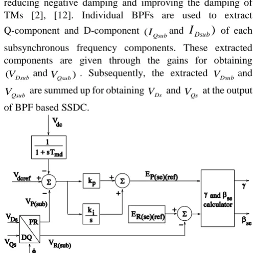
[image:4.595.301.549.272.520.2]upon the range of subsynchronous network mode frequency for which critical TMs are unstable. The pictorial representation of SSDC using BPFs and gains is shown in Fig. 9.
Fig. 9. Pictorial representation of BPF based SSDC. The gains
1 k to
6
k of SSDC are selected in view of reducing negative damping and improving the damping of TMs [2], [12]. Individual BPFs are used to extract Q-component and D-component
Qsub I
( and
I
Dsub)
of eachsubsynchronous frequency components. These extracted components are given through the gains for obtaining
Dsub V
( andVQsub). Subsequently, the extracted VDsub and
Qsub
V are summed up for obtaining
Ds V and
Qs
V at the output of BPF based SSDC.
Fig. 10. Inclusion of the extracted subsynchronous components (obtained from BPF based SSDC) in
SSSC Type-1 controller.
The output of BPF based SSDC (DQ components) is transformed into in-phase and quadrature components namely real and reactive voltages (VPsuband
V
Rsub)
respectively.The real and reactive subsynchronous voltage components
Psub V
( and
V
Rsub)
from BPF based SSDC are added to SSSC voltage controller as presented in Fig. 10.The estimated output of BPF based SSDC is used to adjust SSSC injected voltage to suppress SSR.
V. ANALYSISOFSSRWITHSSSCANDBPFBASED SSDC
[image:4.595.50.287.340.510.2]A. Damping Torque Analysis
The electrical damping torque (Tde) is computed in the
[image:5.595.307.539.149.290.2]range of frequency from 0 to 300 rad/sec. Variation in the electrical damping is observed in Fig. 11. In case study-1, the damping torque having a large negative peak is seen near the frequency of TM-2 (127 rad/sec). In case study-2, the negative damping torque is considerably diminished with BPF based SSDC. Also, the negative value of damping torque is negligible in the full range of TM frequencies.
Fig. 11. Damping torque without and with BPF based SSDC on SSSC.
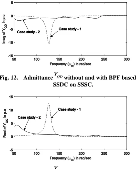
Further, the admittances
QD
Y and
Y are computed in the
range of frequency from 0 to 300 rad/sec. The variations in admittances
QD Y and
Y for case study-1 and case study-2 are shown in Fig. 12 and Fig. 13 respectively.
Fig. 12. AdmittanceYQDwithout and with BPF based SSDC on SSSC.
Fig. 13. AdmittanceYQQwithout and with BPF based SSDC on SSSC.
From the Fig. 12 and Fig. 13, we observe that the negative value of
QD
Y and YQQ is significantly reduced with BPF
based SSDC. From the results of damping torque and impedance analysis, all the TMs are expected to be stable.
B. Eigenvalue Analysis
The eigenvalues for case study-1 and case study-2 are
tabulated in Table-1. From the Table-1 we observe that in case study-1 the frequency of subsynchronous network mode is close to TM-2, and hence the TM-2 is unstable. In case study-2 (SSSC with BPF based SSDC), it is interesting that, all the eigenvalues have negative real parts, which indicating that the system is stable. Comparing with case study-1, the damping of all TMs is considerably improved in case study-2. Table- I: Eigenvalues for case study-1 and case study-2
TM Case study-1: With SSSC
Case study-2: With SSSC and BPF based SSDC
0 -1.7102 ± j 8.2105 -1.3516 ± j 8.2735
1 0.0977 ± j 99.080 -0.4484 ± j 98.477
2 0.1578 ± j 127.00 -0.0850 ± j 126.99
3 -0.6670 ± j 160.46 -0.6838 ± j 160.53
4 -0.3790 ± j 202.85 -0.3986 ± j 202.89
5 -1.8504 ± j 298.17 -1.8504 ± j 298.17
NMsub -3.7702 ± j 128.42 -12.247 ± j 235.37
NMsup -4.8842 ± j 590.20 -5.7889 ± j 613.54
C. Transient Simulation
[image:5.595.55.288.393.677.2]The transient simulation is a time-domain analysis, which is used to validate the outcomes of electrical damping torque and eigenvalue method. In Fig. 14, the time responses for case study-2 are plotted. In Fig. 14, it is interesting to observe that oscillations in time response decrease with time when BPF based SSDC initiated at 5 sec. The results of transient simulation of case study-2 show that the system is stable with BPF based SSDC.
Fig. 14. Step response in case study-2: sectional torque (LPA-LPB) and rotor angle with BPF based SSDC
initiated at t = 5 sec.
VI. RESULTANDDISCUSSION
The investigations and simulation of SSR with hybrid series compensation using fixed capacitor and SSSC for active compensation is presented.
1) We propose a BPF based SSDC to estimate the subsynchronours frequency current components from the transmission line current.
2) The BPF based SSDC is designed to boost the damping of all critical torsional modes with the minimum number of BPFs having good
[image:5.595.306.548.411.578.2]3) The performance of the proposed BPF based SSDC in damping torque and eigenvalue analysis is validated through the transient simulation under large disturbance. 4) The results show that the negative damping is considerably reduced with the proposed SSDC in the entire range of torsional mode frequencies.
5) From the results, it is clear that the outcomes of the three methods are consistent. The outcomes of three methods show the effectiveness of the proposed BPF based SSDC in improving the damping of all torsional modes.
VII. CONCLUSION
In this paper, SSR is analyzed on the modified IEEE FBM model with hybrid compensation using a fixed series capacitor and SSSC. The BPF based SSDC is designed on the basis of TM frequencies and damping torque. The BPF based SSDC is intended to enhance the damping of all torsional modes with minimum number of highly frequency selectivite BPFs. The IEEE FBM has five torsional modes. We propose BPF based SSDC using three BPFs to extract the components of four torsional modes. The results show that the negative damping is considerably reduced with the proposed SSDC in the entire range of torsional mode frequencies. It is evident that, the proposed SSDC effectively mitigates SSR at practical compensation levels.
REFERENCES
1. M. C. Hall and D. A. Hodges, “Experience with 500 kV subsynchronous resonance and resulting turbine generator shaft damage at Mohave generating station,” in Analysis and Control of Subsynchronous Resonance, IEEE Publ. 76 CH 1066-0-PWR, 1976, pp. 22–25. 2. S. Venkateswarlu, M. Janaki, R. Thirumalaivasan and Nagesh Prabhu,
“A review on damping torsional interactions using VSC based FACTS and subsynchronous damping controller,” Annual Reviews in Control, vol. 46, Aug. 2018, pp. 251–264.
3. K. R. Padiyar, Analysis of Subsynchronous Resonance in Power Systems. Boston: Kluwer Academic Publishers, 1999.
4. IEEE Subsynchronous resonance working group, “Proposed terms and definitions for subsynchronous oscillations,” IEEE Trans. on Power App. Syst., vol. PAS-99, no. 2, Mar/Apr. 1980, pp. 506–511.
5. IEEE Subsynchronous resonance working group of the system dynamic performance subcommittee, “Reader's guide to subsynchronous resonance,” IEEE Trans. on Power Syst., vol. 7, no. 1, Feb. 1992, pp. 150–157.
6. M. Bongiorno, J. Svensson and L. Angquist, “On control of static synchronous series compensator for SSR mitigation,” IEEE Trans. on Power Electronics, vol. 23, no. 2, Mar. 2008, pp. 735–743.
7. M. Bongiorno, L. Angquist and J. Svensson, “A novel control strategy for subsynchronous resonance mitigation using SSSC,” IEEE Trans. on Power Delivery, vol. 23, no. 2, Apr. 2008, pp. 1033–1041.
8. M. Bongiorno, J. Svensson and L. Angquist, “Online estimation of subsynchronous voltage components in power systems,” IEEE Trans. on Power Delivery, vol. 23, no. 1, Jan. 2008, pp. 410–418.
9. K. R. Padiyar and Nagesh Prabhu, “A comparative study of SSR characteristics of TCSC and SSSC,” in Proc. PSCC conf., Aug. 2005. 10. D. Rai, S. O. Faried, G. Ramakrishna and Abdel Aty (Aty) Edris, “An
SSSC-based hybrid series compensation scheme capable of damping subsynchronous resonance,” IEEE Trans. on Power Delivery, vol. 27, no. 2, Apr. 2011, pp. 531–540.
11. Liang Wang, Xiaorong Xie, Qirong Jiang and Hemanshu R. Pota, “Mitigation of multimodal subsynchronous resonance via controlled injection of supersynchronous and subsynchronous currents,” IEEE Trans. on Power Syst., vol. 29, no. 3, May. 2014, pp. 1335–1344. 12. R. Thirumalaivasan, M. Janaki and Nagesh Prabhu, “Investigation of
SSR characteristics of hybrid series compensated power system with SSSC,” Advances in Power Electronics, May. 2011, pp. 1–8.
13. K. R. Padiyar and Nagesh Prabhu, “Investigation of SSR characteristics of unified power flow controller,” Electrical Power Systems Research, vol. 74, no. 2, May. 2005, pp. 211–221.
14. K. R. Padiyar, PowerSystem Dynamics – Stability and Control-Second edition. Hyderabad: B. S. Publications, 2002.
15. N. G. Hingorani and L. Gyugyi, Understanding FACTS. New York: IEEE Press, 2000.
AUTHORSPROFILE
S. Venkateswarlu has student IEEE membership from the year of 2018. He received B. Tech degree in electrical and electronics engineering from Jawaharlal Nehru Technological University, Anantapur, India, in 2011 and M. Tech degree in electrical power engineering from Jawaharlal Nehru Technological University, Hyderabad, India, in 2014. He is currently pursing Ph. D degree with the Vellore Institute of Technology, Vellore, India. His research interests including FACTS and power system stability and control.
![Fig. 2. Modified IEEE FBM with SSSC [12].](https://thumb-us.123doks.com/thumbv2/123dok_us/8157110.248700/2.595.302.549.55.206/fig-modified-ieee-fbm-sssc.webp)
![Fig. 5. Type-1 controller of SSSC [12].](https://thumb-us.123doks.com/thumbv2/123dok_us/8157110.248700/3.595.311.537.614.716/fig-type-controller-of-sssc.webp)