An Alternative Current-Error Based Control for VSC
Integration to Weak Grid
Kamyab Givaki
Department of Electrical Engineering University of Strathclyde Glasgow, United Kingdom
Dong Chen
Department of Engineering Glasgow Caledonian UniversityGlasgow, United Kingdom
Lie Xu
Department of Electrical Engineering University of Strathclyde Glasgow, United Kingdom
Yan Xu
State Key Laboratory of Alternate Electrical Power System with Renewable Energy Sources
North China Electric Power University (Baoding) Beijing, China
Abstract— An enhanced current control strategy is proposed for voltage source converters for the integration to weak grids. The control derives from the current-error based vector control. By implementing simple close-loop compensations of both angle and magnitude inputs to the pulse width modulation, the damping of vector control in the weak grid can be significantly improved hence able to deliver full rated power to very weak grid. Due to the presence of the current loop, the fault-ride-through capability can be maintained with no need for mode switching. A comprehensive frequency domain model is employed to analyze the stability. Time domain simulations are further carried out to validate its effectiveness and robustness of integrating to the weak grid with fault-ride-through capability.
Index Terms -- Current Control, Stability, Fault-ride-through, Voltage Source Converter, Weak Grid.
I. INTRODUCTION
The type of power electronics converter called Voltage Source Converter (VSC) is gradually penetrating the power grid as well as the traditional synchronous generators nowadays. As the interface between the traditional AC power system and emerging power grid elements, such as wind turbine [1], Photovoltaic (PV) array [2] , battery energy storage [3], High Voltage DC (HVDC) link [4], the overall rating of VSC is growing higher and higher.
One of the consequences brought about by the growing penetration of VSC is that the grid is becoming relatively “weak” [5]. It is due to not only the reduction of physical inertia but also the growing rating and the distance between VSC and those centralized power plants with physical inertia [6]. Traditionally, the grid connection is considered to be “weak” when the Short Circuit Ratio SCR is as low as 3 and “very weak” when SCR is lower than 1.5. Two factors are considered for low SCR – a large VSC rating and a long delivery distance to the voltage sources with inertia [7].
Vector control is prevalently implemented for VSC integration to the power grid and proved to be able to effectively
harness the fault current under most severe grid voltage sags [8]. However, it is also found that with conventional current-error based vector control, low frequency oscillations may be triggered at very weak grid [9]. It happens when the power to be delivered rises closed to its rated value. And it is found that the weaker the grid is, the less amount of power can be delivered.
In order to cope with the instability of VSC integration in weak grid, various methods have been reported. On type of methods are those based on the virtual synchronous machine [10]-[12], which mimics the power-angle behavior of a synchronous machine to get the power fully delivered from the weak ends. The consequent problem is that such control strategies impose no current loop, which is difficult to completely harness the fault current during voltage dip. Thus, a current-error based control has to be employed as a back-up option so as to be switched to when there is a fault [12]. A current based hysteresis shall be used for such switching scheme. Unfortunately, the switching can cause issues as it is very difficult to determine the hysteresis threshold to keep a balance between investments and the performance.
Another type of control strategy seeks to enhance the damping of vector control so as to maintain the excellent fault-ride-through capability of current-error based vector control [13]-[15]. So far, the reported method is complicated for implementation [13], [14] or is changing the well-established current control scheme internally [15].
As the low frequency oscillation is considered to be lack of damping, a simple compensation method is proposed in this paper. The proposed method is based on conventional vector control strategy. By adding angle and magnitude compensations to the inputs of the Pulse Width Modulation (PMW) of the VSC, the compensation can be easily implemented with no internal change to the well-established current regulation of vector control. The paper is organized as follows: the principles of the proposed control strategy are introduced in Section II; a frequency domain analysis is carried
out in Section III; Section IV covers the time domain studies and the conclusion is drawn in Section V.
II. PRINCIPLES OF THE PROPOSED CURRENT-ERROR BASED VSCCONTROL IN WEAK GRID
A. Modelling of VSC connecting to Weak Grid
For the study of dynamics, the VSC integration to the weak grid can be modelled as an instantaneously controlled voltage source connecting to infinitive AC bus via filter impedances and the line impedances, which is shown in Fig. 1.
As is shown in Fig. 1, R1 and L1 are the resistive and
inductive impedance of the reactor connecting to a 3-phase bridge. C and Ltx are the VSC filter capacitance and leakage
inductance of VSC transformer, respectively. R2 and L2 are the
resistive and inductive impedances of the grid Thevenin Equivalent, which includes both the transmission lines and possible VSC transformer. The converter modulation voltage is denoted as Vconv whereas the capacitor voltage Vc.
B. Control Strategy with Damping Compensation
As is well documented by industry and academia, the traditional vector control cannot enable fully rated power delivery from the weak grid. In this paper, a modified control
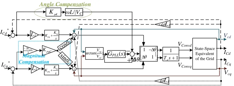
[image:2.612.314.559.117.313.2] [image:2.612.110.505.560.706.2]strategy is proposed based on the conventional vector control, which is illustrated by Fig. 2. As shown, angle compensation and magnitude compensation, which are denoted in the dotted boxes, are added to the conventional vector control strategy.
Fig. 1. Schematic of the benchmark system and proposed VSC control.
Considering the real power output to the grid is linear to the d-axis current in rotating reference frame; whereas in stationary polarity reference frame, the power is determined by the sinusoidal function of the power angle which is the angular difference between the converter modulation voltage vector and the capacitor vector, a closed loop compensation can therefore be established with the corresponding linear relationship between the sinusoidal function of power angle and d-axis current. If only small signal is considered, the differential of the sinusoidal function can be linearized as the differential of the VSC output voltage angle. As a result, the relationship between the differentials of VSC output angle and the d-axis current can be considered as linear. Therefore, a closed-loop compensation can be established based on such relationship as shown in the dotted box of Angle Compensation. A proportional regulator is employed to feed the output of angle compensation as a super-imposing component for the input of PWM block.
Similarly, considering the approximate linear relationship of reactive power against q-axis current and the linear relationship between the VSC output voltage against the reactive power, the relationships of the differentials of the q-axis current and output voltage magnitude can be considered linear as well. Similar to the angular compensation, a closed-loop compensation is proposed as shown in Fig. 1 as the Magnitude Compensation. And magnitude compensation is again fed as a super-imposing component of the magnitude of the modulation signal.
The advantage of the compensation is that it does not change the internal current control of conventional vector control.
III. FREQUENCY DOMAIN ANALYSIS
A. The analytical model in frequency domain
Fig. 1. Schematic of the proposed VSC control.
L1 R1
VDC Vconv VS
PLL ICVC
ICq ICq*
abc dq
VCd VCq
|VC|*
PWM
|VC|
+ _
2
/
3
V
cd
Lead-Lag
K
y x
+
|Vconv|
r
Vconvd*
Vconvq*
ICd
abc dq
θ
+
VCd
ICd*
+
-PI
ICq *
L2 R2
Magnitude Compensation
θadj
ICq
1
2
1 1
T s T s
Angle Compensation P ωsL/|VC|
ICd
+
-+
Vconv
_
ωL _
-+ +
+
+
PI
ωL
PI
Grid
I2I1
ICd*
ICq*
-+
+ +
+
ICd
ICq Vcd
Vcq - L1
+
_
1 1
L1
L1
1 1
s Ts
VConvd
VConvq GPLL(s)
s K
K iq
pq
Angle Compensation
ωL/|VC|
pdC
K
2 3Vcd0
pqC
K
sinθ
0 Magnitude
Compensation
) arctan(
cd cq
V
V State-Space
Equivalent of the Grid
L1
cosθ 0
A frequency domain analytical model is established based on the proposed control strategy of Fig. 1, which is shown in Fig. 2. As is shown in Fig. 2, the proportional and integral gains of angle compensation represented by KpdC and KidC,
respectively the gain for the magnitude compensation is represented by KpqC; Vcd0 and θ0 refer to the values of the
operational capacitor voltage and angle. Kpd, Kid, Kpq, Kiq are
the PI controller parameters for d- and q-axis .
The dynamic of Phase-Locked-Loop (PLL) is represented by a process of GPLL(s)
r (9)
where Kp and Ki are the proportional and integral gains
respectively. The process of arctan(Vcq/Vcd) can be
linearized as with Taylor Expansion at the analytical point of (Vd0,Vq0) as
) ( 1 1 arctan 0 0 2 0 2 0 0 0 d q d q d q d q d q V V V V V V V V V V
(10)
The main circuit of a converter is considered to be connecting to the grid, which can be modelled as a state-space model [16] as
Bu
Ax
x
(11) and T q d Cq Cd Cq
Cd
i
V
V
i
i
i
x
[
,
,
,
,
2,
2]
u
[
V
sd,
V
sq,
V
convd,
V
convq]
T(12) 2 2 2 2 2 2 1 2 2 1 2 2 2 1 0 0 0 0 1 0 0 1 0 0 1 0 0 1 0 0 1 0 0 1 0 0 0 0 L R L L R L C C C C L L R L R L R A b ; 0 0 1 0 0 0 0 1 0 0 0 0 0 0 0 0 1 0 0 0 0 1 0 0 2 2 1 2 L L L L
B b
(13)
B. System analysis
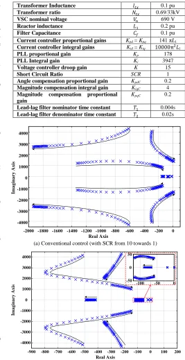
With the frequency domain model shown in Fig. 2, a frequency model analysis can be carried out with root locus analysis shown in Fig. 3. The parameters used are listed in Table I.
TABLE ISYSTEM PARAMETERS
Transformer Inductance 𝑙𝑡𝑥 0.1 pu
Transformer ratio 𝑁𝑡𝑥 0.69/33kV
VSC nominal voltage 𝑉𝑛 690 V
Reactor inductance 𝐿1 0.2 pu
Filter Capacitance 𝐶𝑓 0.1 pu
Current controller proportional gains Kpd = Kpq 141 πL1
Current controller integral gains Kid = Kiq 10000π2𝐿1
PLL proportional gain Kp 178
PLL Integral gain Ki 3947
Voltage controller droop gain K 15 Short Circuit Ratio SCR 1 Angle compensation proportional gain KpdC 0.2
Magnitude compensation integral gain KiqC 4
Magnitude compensation proportional gain
KpqC 0.2
Lead-lag filter nominator time constant 𝑇1 0.004s
Lead-lag filter denominator time constant 𝑇2 0.02s
(a) Conventional control (with SCR from 10 towards 1)
(b) The proposed control (with SCR from 10 towards 1) Fig. 3. Root locus analysis.
As is shown in Fig. 3 (a), with the conventional control strategy, when the SCR becomes very small (SCR = 1 in particular), the system tends to be unstable as the roots reach the right plane, which demonstrates that the conventional control is unable to deliver full power when the grid is very weak. By adding the angular and magnitude compensation, the proposed alternative control can effectively push the poles towards to the left plane, which is shown in Fig. 3(b).
-2000 -1800 -1600 -1400 -1200 -1000 -800 -600 -400 -200 0 -4000 -3000 -2000 -1000 0 1000 2000 3000 4000 Real Axis Im a g in a ry A x is
[image:3.612.52.287.358.642.2]IV. CASE STUDIES
In order to further validate the proposed control, time domain case studies are carried out in this section.
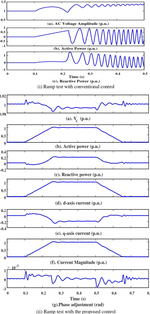
A. Current Ramp Test
In order to test the capability of delivering fully-rated power, a ramp test is carried out in Fig. 4. As is shown in Figs. 4 (i) and (ii), a ramp power order is triggered from Time = 0.1 s, with a ramp rate of 6.6 p.u./s. For the conventional control in Fig. 4(i), the power and voltage start to oscillate when the order reaches around 0.65 p.u. due to lack of damping; whereas it can be seen in Fig. 4(ii) that the fully-rated power can be delivered throughout the ramping-up. At Time = 0.5 s, the ramping-down order is triggered. Similarly, the power ramps down smoothly. Throughout the process, the voltage is maintained within a reasonable variation of 2%. It can also be found in the test that the angular compensation is less than 0.001 rad in this process which means that angle is not shifted in the process so the current of d- and q- axis are still well decoupled according to the capacitor voltage.
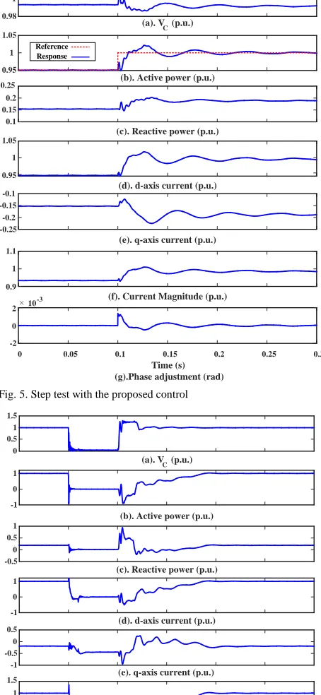
B. Step Test
To further test the performance of the proposed control, a step response is carried out, which is shown in Fig. 5. In order to test the performance in an adverse condition, the system starts with a real power delivery of 0.95 p.u.. A step order of 0.05 p.u. is given at Time = 0.1 s. It can be seen that after oscillation of 0.1 second, the power converges at 1 p.u., which proves that the proposed control has a good stability at the very weak grid.
C. Low-voltage-ride-through Test
Comparing with virtual synchronous control, the main advantage of the proposed control is that it can limit the current after a fault. In order to test the performance of the proposed control, a most adverse 3-phase short fault is considered to be closely at the grid connection point.
As is shown in Fig. 6, the simulation is carried out when SCR = 1 and the VSC is delivering rated power from Time = 0 s. It is assumed that DC side power can be well harnessed. As shown in Fig. 6, a 3-phase fault occurs at Time = 0.1 s. The fault is considered to be closely located at the connection point and the capacitor voltage drops to almost 0 V. It can be seen that the overall current rise up immediately after the fault; however, the sudden overshoot of the current magnitude is limited to less than 1.4 p.u. and then is confined to less than 0.3 p.u. during the fault. After 100 ms, the fault is cleared. The fault current is trying to follow a pre-defined curve and return to the pre-fault values.
From Fig. 6, it can be clearly seen that the proposed control is capable of harnessing the fault current during a 3-phase fault without control mode switching.
(i) Ramp test with conventional control
[image:4.612.314.556.63.569.2](ii) Ramp test with the proposed control Fig. 4. Ramp test with the proposed control
V. CONCLUSIONS
An enhanced vector control strategy is proposed for VSC integration to the weak grid in this paper. The proposed control method is able to deliver full power from the weak grid while still can take advantage of the presence of current loops.
The frequency domain analysis shows that the proposed d-axis current error based angular compensation and q-d-axis current error based magnitude compensation, which is fed into the PWM reference values, can effectively improve the system damping at very weak grid.
(a). AC Voltage Amplitude (p.u.) 0.5
1 1.5
(b). Active Power (p.u.) -1
-0.5 0 0.5 1
0 0.1 0.2 0.3 0.4 0.5
(c). Reactive Power (p.u.) -1
0 1
Time (s)
0.98 1 1.02
(a). VC (p.u.)
(b). Active power (p.u.)
0 0.5 1
(c). Reactive power (p.u.)
-0.2 0 0.2 0.4
(d). d-axis current (p.u.)
0 0.5 1
(e). q-axis current (p.u.)
-0.4 -0.2 0 0.2
(f). Current Magnitude (p.u.)
0 0.5 1
0 0.1 0.2 0.3 0.4 0.5 0.6 0.7 0.8
Time (s) (g).Phase adjustment (rad)
-1 0
1 10
Fig. 5. Step test with the proposed control
Fig. 6. Low-voltage-ride-through test for the proposed control
The proposed compensation can be further validated by time domain simulations that the proposed control can enable full power delivery at steady state ramp operation, power step and the fault-current limiting during a significant transient of 3-phase short circuit at the connection point.
REFERENCES
[1] S. I. Nanou and S. A. Papathanassiou, "Grid Code Compatibility of VSC-HVDC Connected Offshore Wind Turbines Employing Power Synchronization Control," in IEEE Trans.Power Syst., vol. 31, no. 6, pp. 5042-5050, Nov. 2016.
[2] S. Dhar and P. K. Dash, "Harmonic Profile Injection-Based Hybrid Active Islanding Detection Technique for PV-VSC-Based Microgrid System," in IEEE Trans. Sustain. Energy, vol. 7, no. 4, pp. 1473-1481, Oct. 2016.
[3] M. I. Daoud, A. M. Massoud, A. S. Abdel-Khalik, A. Elserougi and S. Ahmed, "A Flywheel Energy Storage System for Fault Ride Through Support of Grid-Connected VSC HVDC-Based Offshore Wind Farms," in IEEE Trans. on Power Syst., vol. 31, no. 3, pp. 1671-1680, May 2016. [4] L. P. Kunjumuhammed, B. C. Pal, R. Gupta and K. J. Dyke, "Stability Analysis of a PMSG-Based Large Offshore Wind Farm Connected to a VSC-HVDC," in IEEE Trans. Energy Conv., vol. 32, no. 3, pp. 1166-1176, Sept. 2017.
[5] N. P. W. Strachan and D. Jovcic, "Stability of a Variable-Speed Permanent Magnet Wind Generator with Weak AC Grids," IEEE Trans. Power Del., vol. 25, pp. 2779-2788, 2010.
[6] "IEEE Guide for Planning DC Links Terminating at AC Locations Having Low Short-Circuit Capacities," IEEE Std. 1204-1997, pp. 1-216, 1997.
[7] L. Zhang, L. Harnefors, and H. P. Nee, "Interconnection of Two Very Weak AC Systems by VSC-HVDC Links Using Power-Synchronization Control," IEEE Trans. Power Syst., vol. 26, pp. 344-355, 2011. [8] A. Kirakosyan, M. S. E. Moursi and V. Khadkikar, "Fault Ride Through
and Grid Support Topology for the VSC-HVDC Connected Offshore Wind Farms," in IEEE Trans. on Power Del., vol. 32, no. 3, pp. 1592-1604, June 2017.
[9] A. Egea-Alvarez, C. Barker, F. Hassan, and O. Gomis-Bellmunt, "Capability curves of a VSC-HVDC connected to a weak AC grid considering stability and power limits," in Proc. 11th IET International Conference on AC and DC Power Transmission, , 2015, pp. 1-5. [10] L. Zhang, L. Harnefors, and H. P. Nee, "Power-Synchronization Control
of Grid-Connected Voltage-Source Converters," IEEE Trans. Power Syst., vol. 25, pp. 809-820, 2010.
[11] Q.-C. Zhong and Weiss, "Synchronverters: Inverters that mimic synchronous generators," IEEE Trans. Ind. Electron., vol. 58, pp. 1259-1267, 2011.
[12] M. Ashabani and Y. A.-R. I. Mohamed, "Integrating VSCs to Weak Grids by Nonlinear Power Damping Controller With Self-Synchronization Capability," IEEE Trans. Power Syst., vol. 29, pp. 805-814, 2014.
[13] A. Egea-Alvarez, S. Fekriasl, F. Hassan, and O. Gomis-Bellmunt, "Advanced vector control for voltage source converters connected to weak grids," IEEE Trans. Power Syst., vol. 30, pp. 3072-3081, 2015. [14] Y. Li et al., "Power Compensation Control for Interconnection of Weak
Power Systems by VSC-HVDC," in IEEE Trans. on Power Del., vol. 32, no. 4, pp. 1964-1974, Aug. 2017.
[15] B. Yuan, J. Xu, C. Zhao, Y. Yuan," An Improved Phase-Locked-Loop Control with Alternative Damping Factors for VSC Connected to Weak AC System," Journal of Control Science and Engineering, Volume 2016 [16] K. Givaki and L. Xu, "Stability analysis of large wind farms connected
to weak AC networks incorporating PLL dynamics," in Proc. International Conf. on Renewable Power Generation 2015, pp. 1-6. 0.98
1 1.02
(a). V
C (p.u.)
(b). Active power (p.u.)
0.95 1 1.05
Reference Response
(c). Reactive power (p.u.)
0.1 0.15 0.2 0.25
(d). d-axis current (p.u.)
0.95 1 1.05
(e). q-axis current (p.u.)
-0.25 -0.2 -0.15 -0.1
(f). Current Magnitude (p.u.)
0.9 1 1.1
0 0.05 0.1 0.15 0.2 0.25 0.3
Time (s) (g).Phase adjustment (rad)
-2 0 2 10
-3
0 0.5 1 1.5
(a). VC (p.u.)
(b). Active power (p.u.)
-1 0 1
(c). Reactive power (p.u.)
-0.5 0 0.5 1
(d). d-axis current (p.u.)
-1 0 1
(e). q-axis current (p.u.)
-1 -0.5 0 0.5
(f). Current Magnitude (p.u.)
0 0.5 1 1.5
Time (s) (g).Phase adjustment (rad)
-0.05 0 0.05