City, University of London Institutional Repository
Citation
:
Gulistan, A., Ghosh, S. ORCID: 0000-0002-1992-2289, Ramachandran, S. and
Rahman, B. M. ORCID: 0000-0001-6384-0961 (2017). Efficient strategy to increase higher
order inter-modal stability of a step index multimode fiber. Optics Express, 25(24), pp.
29714-29723. doi: 10.1364/OE.25.029714
This is the published version of the paper.
This version of the publication may differ from the final published
version.
Permanent repository link:
http://openaccess.city.ac.uk/20483/
Link to published version
:
http://dx.doi.org/10.1364/OE.25.029714
Copyright and reuse:
City Research Online aims to make research
outputs of City, University of London available to a wider audience.
Copyright and Moral Rights remain with the author(s) and/or copyright
holders. URLs from City Research Online may be freely distributed and
linked to.
City Research Online:
http://openaccess.city.ac.uk/
[email protected]
Efficient strategy to increase higher order
inter-modal stability of a step index multimode
fiber
AAMIR
GULISTAN,
*SOUVIK
G
HOSH, S. RAMACHANDRAN, ANDB .M.
A. R
AHMANAbstract: We demonstrate a novel approach to enhance the mode stability through increased
effective index difference (∆ne f f) between the higher-order modes (LP18,LP09andLP19) of a
multimode fiber. Fibers with large diameters have bigger effective mode areas (Ae f f) and can
be useful for high power lasers and amplifiers. However, a large mode area (LMA) results in an increased number of modes that can be more susceptible to mode coupling. The modal effective index difference (∆ne f f) strongly correlates with mode stability and this increases as the modal
order (m) increases. We report here that the mode spacing between the higher order modes can be
further enhanced by introducing doped concentric rings in the core. In our work, we have shown a more than 35% increase in the mode spacing between the higher order modes by optimizing the doping profile of a LMA fiber. The proposed design technique is also scalable and can be applied to improve the mode spacing between different higher order modes and their neighboring antisymmetric modes, as necessary.
© 2017 Optical Society of America
OCIS codes:(060.2400) Fiber properties; (060.2310) Fiber optics; (230.2285) Fiber devices and optical amplifiers;
(060.2280) Fiber design and fabrication.
References and links
1. D. J. Richardson, J. Nilsson, and W. A. Clarkson, “High power fiber lasers: current status and future perspectives,” J. Opt. Soc. Am. B27, B63–B92 (2010).
2. M. N. Zervas and C. A. Codemard, “High power fiber lasers: A review,” IEEE J. Sel. Top. Quantum Electron.20(5),
219–241 (2014).
3. J. W. Nicholson, J. M. Fini, A. M. DeSantolo, E. Monberg, F. DiMarcello, J. Fleming, C. Headley, D. J. DiGiovanni, S. Ghalmi, and S. Ramachandran, “A higher-order-mode Erbium-doped-fiber amplifier,” Opt. Express18(17),
17651–17657 (2010).
4. J. S.Wong, W.Wong, S. Peng, J. McLaughlin, and L. Dong, “Robust single-mode propagation in optical fibers with record effective areas,” CLEO-2005, CPDB10 (2005).
5. J. W. Nicholson, J. M. Fini, A. M. DeSantolo, X. Liu, K. Feder, P. S. Westbrook, V. R. Supradeepa, E. Monberg, F. DiMarcello, R. Ortiz, C. Headley, and D. J. DiGiovanni, “Scaling the effective area of higher-order-mode erbium-doped fiber amplifiers,” Opt. Express20(22), 24575–24584 (2012).
6. S. Wielandy, “Implications of higher-order mode content in large mode area fibers with good beam quality,” Opt. Express15(23), 15402–15409 (2007).
7. F. Stutzki, F. Jansen, H. J. Otto, C. Jauregui, J. Limpert, and A. Tunnermann, “Designing advanced very-large-mode-area fibers for power scaling of fiber-laser systems,” Optica1(4), 233–242 (2014).
8. K. Rottwitt, S. M. M. Friis, M. A. U. Castaneda, E. N. Christensen and J. G. Koefoed, “Higher order mode optical fiber Raman amplifiers,” 18th International Conference on Transparent Optical Networks (IEEE, 2016).
9. S. Ramachandran, J. W. Nicholson, S. Ghalmi, M. F. Yan, P. Wisk, E. Monberg, and F. V. Dimarcello, “Light propagation with ultralarge modal areas in optical fibers,” Opt. Lett.31(12), 1797–1799 (2006).
10. J. M. Fini and S. Ramachandran, “Natural bend-distortion immunity of higher-order-mode large-mode-area fibers,” Opt. Lett.32(7), 748–750 (2007).
11. A. Argyros, R. Lwin, and M. C. J. Large, “Bend loss in highly multimode fibres,” Opt. Express16(23), 18590–18598
(2008).
12. S. Ramachandran, J. M. Fini, M. Mermelstein, J. W. Nicholson, S. Ghalmi, and M. F. Yan, “Ultra–large effective–area, higher–order mode fibers: a new strategy for high-power lasers,” Laser Photon. Rev.2(6), 429–448 (2008).
13. A. W. Snyder and J. Love,Optical Waveguide Theory(Springer Science & Business Media, 1983).
14. B. M. A. Rahman and J. B. Davies, “Finite-element solution of integrated optical waveguides,” J. Lightwave Technol.
2(5), 682–688 (1984).
15. B. M. A. Rahman and J. B. Davies, “Penalty function improvement of waveguide solution by finite elements,” in IEEE Trans. Microw. Theory Techn.32(8), 922–928 (1984).
16. S. Virally, N. Godbout, S. Lacroix, and L. Labonte, “Two-fold symmetric geometries for tailored phasematching in birefringent solid-core air-silica microstructured fibers,” Opt. Express18(10), 10731–10741 (2010).
17. M. Koshiba and K. Inoue, “Simple and efficient finite–element analysis of microwave and optical waveguides,” IEEE Trans. Microw. Theory Techn.40(2), 371–377 (1992).
18. V. Rastogi and K. S. Chiang, “Analysis of segmented-cladding fiber by the radial-effective-index method,” J. Opt. Soc. Am. B21(2), 258–265 (2004).
19. A. Kumar, V. Rastogi, A. Agrawal, and B. M. A. Rahman, “Birefringence analysis of segmented cladding fiber,” Appl. Opt.51(15), 3104–3108 (2012).
20. B. M. A. Rahman and J. B. Davies, “Vector–H finite element soluion of GaAs/GaAlAs rib waveguides,” Proc. IEEE
132(6), 349–353 (1985).
21. M. R. Karim, B. M. A. Rahman, and G. P. Agrawal. “Dispersion engineeredGe11.5As24Se64.5nanowire for
supercontinuum generation: A parametric study,” Opt. Express22(25), 31029–31040 (2014).
22. N. Lindlein, G. Leuchs, and S. Ramachandran, “Achieving Gaussian outputs from large-mode-area higher-order-mode fibers,” Appl. Opt.46(22), 5147–5157 (2007).
1. Introduction
High power lasers and amplifiers are necessary for many applications in the field of science and technology. Recent research shows remarkable increase in the output power of fiber lasers [1, 2]. Compared to solid state lasers, fiber lasers are more compact, lightweight and flexible. Various approaches have been considered to increase the power of fiber based lasers and amplifiers. However, an increase in power brings the need to mitigate for non-linearities in the fiber such as Brillouin and Raman scattering, four-wave mixing (FWM) and self-phase modulation [3, 4]. Mitigating these non-linear effect require large mode area (LMA) fibers in which optical mode is less intense. Therefore, much of the recent research focuses on LMA fibers for the high-power fiber lasers [5]. Multimode fibers (MMF) offer large mode areas and high beam quality [6] but the existence of many modes can result in random mixing between the desired mode and unwanted modes. However, recent research shows that higher order modes (HOM) have the ability to provide for more stable operation because the signal stability increases with an increase in the modal order [5], [7, 8]. A number of approaches have been presented in recent years to use HOM for high power fiber lasers and amplifiers. One of the approaches involves the coupling of light from the fundamental mode to a single desired HOM using fiber Bragg gratings and then to propagate light in the higher order mode amplifying fiber [9]. These techniques provide considerably larger modal areas as well as more stable operation as described above. Moreover, for a given effective area, HOMs are also less sensitive to area reduction than the fundamental mode when bending [10,11]. At the same time, compared to the fundamental mode, higher order modes are less prone to mode coupling as with the increase in the modal order (m) the difference
in effective index (∆neff) between a given higher mode (LP0m) and its nearest antisymmetric mode (LP1m) also increases [12].
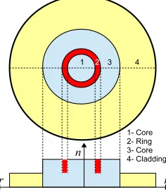
In this paper, we have proposed a novel approach to increase the∆neffthat would result in a resilience to mode-mixing and more stable signal propagation with the advantage of significantly larger effective mode area (Ae f f) by using HOMs. Annular rings with doping of increased or
reduced refractive index are used at particular radial locations inside the core as shown in Fig. 1, such that the effective refractive index (ne f f) of a desired mode is increased or reduced [13]. To
demonstrate our concept, we have considered a MMF of numerical aperture (NA=0.22) with core radius (Rcor e=25µm) and refractive index (ncor e=1.457). Similarly, cladding radius and
refractive index are taken as (Rclad=62.5µm) and (nclad=1.4403), respectively. For this study
Fig. 1. Ring doping schematic of a MMF with the change in the refractive index along r-axis.
2. Theory
2.1. Modal solutions
Use of the higher order mode (HOM) of a multimode fiber (MMF) shows several advantages which includes mode area scaling to control laser high power and dispersion management for ultra-short pulses. Modal instabilities in HOMs are a common problem arising due to external perturbations, such as bending and fabrication imperfections. According to the symmetry rule, bend perturbation is odd in nature and direct coupling arises between even and odd order modes. Among the many modes guided by a MMF, sometimes a desired dominant mode (LP0m) may
transfer its energy to its nearest anti-symmetric (LP1(m+1)andLP1(m−1)) modes on both sides [12].
A low effective index difference (∆ne f f) between adjacent modes enhances the modal energy
transfer which results actual modal energy loss along with the interference effects. This could result in inter-mode mixing in a MMF. Although a lower order (lower value ofm) mode may
be easier to excite, a higher value ofm gives larger modal separation (∆ne f f) values, so a
compromise is needed. However, for a given value ofm, if the modal separation to the nearest
anti-symmetric modes can be increased, this would be a more preferable design. Here, a novel MMF design with several concentric material strips at strategically located positions is proposed to increase the∆ne f f=(n0e f fm −ne f f1m)in desired modes, such as,LP18,LP09andLP19as a high
∆ne f f would restrict unwanted modal energy transfer due to external perturbations. Instead of
using a perturbation approach, we have used a rigorous full vectorialH-field based finite element
method (FEM) [14, 15] to find the modal solutions of our proposed MMF design. The FEM is one of the most numerically efficient and accurate approaches to obtain the modal solutions of an optical waveguide, to calculate the propagation constant (β), effective index (ne f f=β/ko, where
wavenumberkois given by 2π/λ) andAe f f.
In order to increase the modal solution accuracy, the available two-fold symmetry of the fiber is exploited and only one-quarter of the structure is simulated [16,17]. This allows more dense mesh distribution in the quarter structure of the fiber instead of distributing the same mesh over the whole structure. The polar mesh [18] discretization is also used, which can accommodate the discretized elements more efficiently at the circular boundaries, which can provide more accurate results compared to the mesh distribution based on the Cartesian coordinate system [19]. It is well known that the simulation accuracy of the FEM is highly dependent on the number of discretized elements used. Variation of the effective index (ne f f) with the number of mesh elements (N) is
shown in Fig. 2 by a solid black line for the higher orderLP09mode. It can be observed that
initially as mesh density increases thene f f also increases rapidly and then asymptotically settles
Fig. 2. Variation ofne f f of theLP09mode with the mesh number (N) and convergence
realized with the Aitken extrapolation technique.
number of elements used is, N=7×10⁴and it increases to the 5thdecimal place when N=5×10⁵.
HereN, is the number of triangular elements used to represent a quarter of the MMF. A powerful
Aitken’s extrapolation technique is used to test the convergence of the modal solutions [20,21]. Three successivene f f values for corresponding mesh divisions with a geometric ratio are used in
the Eq. (1).
n∞eff =neff(r+1)−
[neff(r+1)−neff(r)]2
neff(r+1)−2neff(r)+neff(r−1) (1)
Using Eq.1 the extrapolated values ofn∞e f f are shown in the Fig.2 by the red-dashed line. Aitken’s
values are calculated for the mesh values N=7.66×10⁴, 3.07×10⁵, and 1.23×10⁶increased in
fixed geometric ratio yielding thene f f values 1.4460355, 1.4461157,and 1.4461358, respectively.
It should be noted that in each solution the mesh density is two times (no. of the elements is four times) that of the previous and thus the geometrical mesh ratio is kept constant. From these values a more accurate extrapolated value of 1.4461398 is obtained. Similarly, Fig. 2 clearly shows the convergence of the extrapolated results and raw FEM results. As the trend ofne f f with
increasingNfor different modes is similar, so the accuracy of∆ne f f between two modes with
increasingNis also greater.
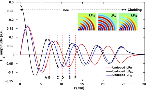
Fig. 3. Variations ofHyfields of theLP18,LP09, andLP19modes along the r-axis of MMF,
[image:5.612.179.430.507.662.2]2.2. Mode stability
As previously discussed, higher order modes (HOM) provide the unique benefit of increased stability due to a greater mode spacing (∆ne f f) compared with that of the fundamental modes
(LP01) [22]. In this paper, we propose a unique approach that can reduce mode mixing between the
higher orderLP18,LP09andLP19modes, that could alternatively only be possible by considering
a much higher modal order. For our design, we usedLP09as the central propagation mode and
modified the refractive index profile of the fiber such that the mode stability between symmetric (LP09) and the two nearest antisymmetric (LP18andLP19) modes is increased. A measure of the
modal stability can be defined using the effective index differences as,S1=∆ne f f(LP18−LP09)
andS2=∆ne f f(LP09−LP19). However, if required any other HOM of interest can also be selected
and using the same concept its mode stability can be enhanced. For this structure, the effective indices of theLP18,LP09, and LP19are calculated as 1.447317, 1.4461104, and 1.4448554,
respectively, yieldingS1=0.0012066 andS2=0.001255. The variation of the dominantHyfield
profile of theLP18, LP09 and LP19 modes is shown in Fig. 3 by red, black and blue lines,
respectively.Hyfield contours of theLP18,LP09andLP19modes are also shown Fig. 3 as insets.
It can be observed that the field profile ofLP09shown by a black line, has the highest magnitude
at the center (r=0) of the fiber and eight zero values along the radial direction. The antisymmetric LP18 andLP19 modes shown with red and blue lines, respectively, have zero field values at
the center (r =0) of the fiber. The dominantHyfields of theLP18andLP19modes have eight
and nine zero field values along the radial direction, respectively. Table 1 shows all the radial locations where these modes have zero field values. For example,LP18has its first three zero
field locations atr=0, 3.78 and 6.966µm. Using these zero crossings we have identified multiple
[image:6.612.118.497.560.619.2]locations that are suitable for doping such that the mode stability (S1andS2) can be increased.
Table 1. Zero crossing locations of field profiles of theLP18,LP09andLP19modes along
r-axis (µm).
Mode Location of zero crossings along r-axis (µm)
L P18 0 3.78 6.966 10.138 13.279 16.315 19.557 22.684 L P09 2.16 5.16 8.125 11.078 13.99 16.89 19.9 22.79 L P19 0 3.36 6.193 9.058 11.867 14.577 17.472 20.252
Some specific points, A, B, C, D, E and F are selected as shown in Fig. 3, where eitherLP18
orLP19has zero crossing. The reason for choosing these points is that we want to have less of an
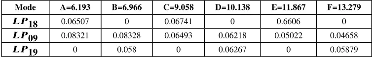
effect on one of the mode and have more of an effect on the other two though using strips of different doping. The modal field values at these points are also given in Table 2. For example at
Table 2. Field values ofLP18,LP09andLP19at A, B, C, D, E and F points.
Mode A=6.193 B=6.966 C=9.058 D=10.138 E=11.867 F=13.279
L P18 0.06507 0 0.06741 0 0.6606 0 L P09 0.08321 0.08328 0.06493 0.06218 0.05022 0.04658
L P19 0 0.058 0 0.06267 0 0.05879
point A, theHyfield value ofLP19is zero, whereas, the field values ofLP18andLP09modes
are 0.06507 and 0.08321, respectively. As a result any change of refractive index doping at point A will have an almost negligible effect on theLP19mode and comparatively more of an effect on
theLP09than theLP18mode. However, at point F, where theHyfield value ofLP18mode is
zero and these values forLP09andLP19modes are 0.04658 and 0.05879, respectively. Hence, at
LP09mode. This will result in an increase in effective index both of these modes while keeping
the effective index of theLP18mode unchanged, and a suitable selection can result in an increase
in the modal stability. In order to increase the∆ne f f between these modes a circular strip of 0.3
µmwidth is considered that can have an increased or reduced refractive index by∆n. Here, we
have taken∆n=0.0167, which is also the difference between the core and cladding refractive
indices. However, different values of∆nin these strips can be chosen according to the required
level of stability between modes.
3. Numerical results
Table 3 shows the effect of doping a single individual layer at the above mentioned six positions along the r-axis. The second column of Table 3 shows the original∆ne f f between the modes
without any doping. It can be noted that the∆ne f f betweenLP09andLP19is slightly higher than
the∆ne f f betweenLP18andLP09. The values of+∆nor−∆non particular points are chosen
such that the effect on the central mode, in our caseLP09, is negligible or can be compensated
with another doping layer where∆nis chosen with an opposite sign to the first point. For example,
in layer A (at r=6.193µm),+∆nis chosen to increase the stability,S1betweenLP09andLP19,
but unfortunately this reduces the stability,S2 between LP18 andLP09. On the other hand a
reduction of refractive index in layer B increases modal separationS2, but reduces that ofS1.
However, an increase of refractive index in layer E and reduction in layer F enhances both theS1
andS2modal stabilities. The same doping approach is considered at all six positions with either +∆nor−∆nas shown in Table 3. Here, two approaches can be considered;
1. Using single layer doping to increase the stability between modes. 2. Using the combination of two or more layers to increase the stability.
Table 3. Individual strip doping effect on∆ne f f at points A, B, C, D, E, and F.
∆ne f f
Without
doping
A B C D E F
+∆n -∆n +∆n -∆n +∆n -∆n
S1=LP18-LP09 0.0012066 0.0010515 0.0015574 0.0012192 0.0014932 0.0013553 0.0014033
S2=LP09-LP19 0.001255 0.0015544 0.0010634 0.0015037 0.0012711 0.0014385 0.0014217
In Table 4 the above described approaches are shown with the percentage increase in∆ne f f
(S1andS2). The percentage increase is calculated with respect to the original∆ne f f between the
modes as shown in column two. Here, three different options are suggested depending upon the required increase in the∆ne f f. It can be seen that with a single layer of−∆ndoping at point F,S1
andS2are increased by 16% and 14%, respectively. However, using two layers (at E & F points)
the stabilitiesS1andS2between modes can be increased by 20% and 23%, respectively. It should
be noted that the∆ndoping at points E and F are taken as positive and negative, respectively. For
further enhancement, three layers can be doped simultaneously at points C, D, and E which results in an increase of 35% and 38% for∆ne f f(LP18−LP09)and∆ne f f(LP09−LP19), respectively.
Hence, our proposed design results in increased modal spacing between the higher order modes
LP18,LP09 andLP19, thus providing for more stable and mode-mixing resistant operation.
Figure 4 shows the refractive index profile for three layer doping at C, D and E points. Here, ∆nat points C and E are taken as positive such that it increases the local refractive index from
1.457 to 1.4737. Whereas, at point D,∆nis taken as negative resulting in the local index being
equal to that of the cladding. The combination is chosen such that∆ne f f(LP18−LP09)and
∆ne f f(LP09−LP19)have an almost equal increase. Here, all three annular strips are centered at
Table 4. Percentage increase in the∆ne f f using individual and combination approach.
∆ne f f
Without
doping
F only E & F C, D & E
∆ne f f % Increase ∆ne f f % Increase ∆ne f f % Increase
S1=LP18-LP09 0.0012066 0.0014033 16 0.0014551 20 0.0016254 35 S2=LP09-LP19 0.001255 0.0014217 14 0.0015318 23 0.0017357 38
Fig. 4. Refractive index profile of the modified MMF along r- axis with±∆nat C, D and E
points.
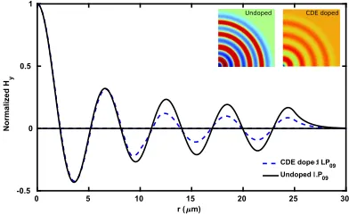
propagation mode in our design. Hence next, the effect of three layers of doping at points C, D, and E points on the field profile ofLP09is studied. Figure 5 shows theHyfield profile of theLP09
mode before and after doping. The black line shows the undoped field profile whereas the dotted blue line represents the field profile ofLP09after doping these three layers at C, D, and E. It can
be observed that until the appearance of the doped strips the field profile was almost unchanged, however beyond these strips, the field value is reduced compared to that of the original undoped fiber.
0 5 10 15 20 25 30
r ( m) -0.5
0 0.5 1
Normalized H
y
[image:8.612.206.402.416.536.2]CDE doped LP09 Undoped LP09 Undoped CDE doped
Fig. 5. Variations in theHyfields ofLP09modes along the r-axis of the undoped fiber and
the fiber with C, D, and E layers doped. The contour field profiles are also shown inset.
The∆n=0.0167 value used for the circular strips C, D, and E is equivalent to the refractive
index difference between core and cladding of the fiber but of necessary other∆nvalues or even
unequal values can be used for a particular design. To observe the effect of increased or reduced value of∆n, we have halved the refractive index difference as,±∆n=0.00835 and found that the
modal stabilitiesS1andS2reduces to 18% and 19%, respectively. However, when refractive index
difference is increased to double; as±∆n=0.0334, the modal stabilitiesS2increases to 74% but S1increased only slightly to 41%, as field profiles were distorted significantly. However, it can be
stated that a significant enhancement in the modal stability can be achieved by this approach. Although we have focused on the enhancement of mode spacing between LP09 and its
applied for any higher order modes. As an example, for the enhancement of mode spacing ofLP08
mode and its neighboring antisymmetricLP17andLP18modes, we have carried out additional
simulations after introducing the similar annular rings. Similar six zero crossing points,A0to F0forLP17orLP18are identified asA0=6.928,B0=7.856,C0=10.138,D0=11.518,E0=13.279, F0=15.098 (inµm). Numerical simulations were carried out with strips width of 0.3µmand
±∆n=0.0167 introduced at these points. Table 5 shows the increase in∆ne f f(LP17−LP08)
and∆ne f f(LP08−LP18)with single layer (F
0
) or multiple layers (E0,F0and (C0,D0,E0) with
perturbed annular strips. It can be observed that the stability is increased to 46% for theLP08
mode when three annular layers at (C0,D0,E0) points are used. This confirms that the concept
[image:9.612.118.495.256.310.2]presented here can be applied to any higher order modes, as necessary.
Table 5. Percentage increase in the∆ne f fofLP08mode and its neighboring antisymmetric
modes using individual and combination of two or three strips doping.
∆ne f f
Without
doping
F0only E0&F0 C0,D0&E0
∆ne f f % Increase ∆ne f f % Increase ∆ne f f % Increase
LP17-LP08 0.0010746 0.0012218 14 0.0013424 25 0.0015759 47
LP08-LP18 0.0011146 0.0013136 18 0.0015187 36 0.0016256 46
3.1. Fabrication tolerance of strips width
Here, we demonstrate the effect of possible variations in doping that can occur during the fabrication process. As the combined doping of the three layers at points C, D, and E could be more sensitive to fabrication tolerances than the two or single layer doping we will consider the three layers (C, D and E) case for further investigation. The effects of a change in the layer width (w) from 0.3µmto a higher or lower value are shown in Fig. 6. As discussed earlier, with w=0.3
µmthe stabilitiesS1andS2between the modes are 35% and 38%, respectively. With an increase
in the width from w=0.3µmto w=0.4µm, the stabilitiesS1andS2further increase to 38% and
51%, respectively. This is because the area of the doped layer is increased when the width is changed from 0.3µmto 0.4µmthus increasing its overall effect. However, as the width deceases
to w=0.20µm, the stability improvement reduces but still it remains above 25%. Hence, in our
proposed design the modal stability improvement will remain at least 25% larger for a width change of±0.1 µm.
[image:9.612.193.418.507.642.2]3.2. Fabrication tolerance of strips center location
In our proposed design three layers are centered at points C=9.058µm, D=10.138 µmand
E=11.867µmand during fiber drawing these positions may change. Figure 7 shows the effect of a
change in the location of the doped layer’s center points. It can be seen that the stability is highly dependent on the specified locations in Fig. 3. When there is no shift in the location of the strip’s centers, the stability improvement is larger than 35%. With a tolerance of±0.05µmthe stability
improvement still remains above 27% but as the shift is increased to 0.1µmtheS1improvement
drops to 20% whileS2improvement is increased to 51%. Moreover, when the annular strips shift
is -0.1µm, the modal stabilityS1improvment increases to 46% but that ofS2decreases to 27%.
For comparison the spacing between the modes before introduction of the C, D and E layers is also shown by two horizontal lines.
Fig. 7. Effect on the∆ne f f of a variation in the position of C, D, and E layers from center
location.
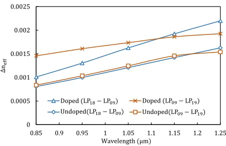
3.3. Fabrication tolerance of wavelength change
The above analysis is carried out at the center wavelength ofλ=1.05µm. However, when the
operating wavelength changes from this value the stability between modes can also change. To observe the impact of wavelength change on the stability between the modes, we varied the operating wavelengths and this is shown in Fig. 8. It can be observed that the stability between the
LP18,LP09andLP19modes increases with an increase in the wavelength. It should be noted that
the refractive index of a material is also dependent on the wavelength. In our analyses we have used the core and clad refractive index values asncor e=1.457 andnclad=1.4403 respectively at
λ=1.05µm. However, if required the effect of refractive index variation with the wavelength can
also be included. It should be noted that without doping at the C, D, and E layers, the stability increases almost linearly with an increase in the wavelength. The increased wavelength reduces mode confinement and effective index values and this also increases the separation between the modal index values. A similar effect is noticed after the introduction of doping at layers C, D and E layers. When the center wavelength isλ=1.05 µm, the modal stability values are S1=0.0016254 andS2=0.0017357, which are improvements of 35% and 38% from their undoped
values, respectively. However, it can be noted that with a change in the wavelength fromλ=1.05
µmtoλ=0.85 µmthe stability difference after doping shows a similar trend to the undoped
case. The modal stability values atλ=0.85 µmreduced toS1=0.0010095 andS2=0.0014572,
however this reflects a 25% and 74%, improvement from the standard fiber. Similar behavior is observed when the center wavelength is increased toλ=1.25µmand modal stability increases to S1=0.002199 andS2=0.0019263, and these reflect improvements 35% and 25% increase from the
[image:10.612.192.418.245.382.2]Fig. 8. Effect on the∆ne f f with the change in wavelength(λ)
µmtoλ=1.25 µm, and hence the proposed design results in a sufficiently improved stability
between the competing modes and is also expected to provide for large effective mode areasAe f f
because of operating in HOMs [12].
4. Conclusions
We have proposed a novel design approach, which has been validated by rigorous numerical analysis, to improve the stability between the modes can be increased by more than 35%. Increasing the∆ne f fbetween modes results in a more stable and mode-mixing resistant operation
[image:11.612.191.417.98.244.2]