Three-dimensional semi-analytical
solutions for the transient response of
functionally graded material cylindrical
panels with various boundary conditions
Xu Liang
1, Yu Deng
1, Xue Jiang
2, Zeng Cao
1, Yongdu Ruan
1,
Jianxing Leng
1, Titao Wang
1and Xing Zha
1Abstract
In this paper, a 3D semi-analytical method is proposed by introducing the Durbin’s Laplace transform, as well as its numerical inversion method, state space approach and differential quadrature method to analyse the transient behaviour of functionally graded material cylindrical panels. Moreover, to investigate the effectiveness of the proposed semi-analytical solution, four boundary conditions are used to undertake the analyses. Comparing the proposed approach with other theoretical methods from the literatures, we see better agreements in the natural frequencies. Besides, the semi-analytical solution acquires nearly the same transient response as those obtained by ANSYS. Convergence studies indicate that the proposed method has a quick convergence rate with growing sample point numbers along the length direction, so do layer numbers increase along the radial direction. The effects of thickness/outer radius ratio, length/outer radius ratio and functionally graded indexes are also studied. When carbon nanotube is added to functionally graded material cylindrical panel, the composite structures have been reinforced greatly. The proposed 3D semi-analytical method has high accuracy for the analysis of composite structures. This study can serve as a foundation for solving more complicated environments such as fluid–structure interaction of flexible pipe or thermal effect analysis of functionally graded material in aerospace field.
Keywords
Numerical inversion of Laplace transform, cylindrical panels, functionally graded material, differential quadrature method, state space approach
Introduction
Functionally graded materials (FGMs), whose property gradient is caused by chemical composition, atomic order or microstructure, have attracted much attention of many groups.1–4Because of their advantageous stiffness-to-weight ratio and strength-to-stiffness-to-weight ratio as well as their tendency for high performance, FGM structures play important roles in ocean engineering, fuselage and submarine components. Therefore, the research on the dynam-ic response of FGM structure is of great signifdynam-icance to the development of the frontier in aerospace engineering, civil engineering, ocean engineering, etc.
Over the course of history, various plates/shells theories have been used to analyse FGM structures. Using the framework of the non-local strain gradient theory and Hamilton principle, Li et al.5 deduced the governing equations and analysed the natural frequencies of FGM beam. Parida and Mohanty6investigated the free vibra-tion of FGM plates by the use of higher order shear deformavibra-tion plate theory (HSPT) on the foundavibra-tion of
1
Department of Ocean Engineering, Zhejiang University, Hangzhou, P. R. China 2
Department of Naval Architecture, Ocean and Marine Engineering, University of Strathclyde, Glasgow, UK
Corresponding author:
Xue Jiang, Department of Naval Architecture, Ocean and Marine Engineering, University of Strathclyde, Glasgow G4 0LZ, UK. Email: [email protected]
Journal of Low Frequency Noise, Vibration and Active Control 0(0) 1–22
!The Author(s) 2019 DOI: 10.1177/1461348419855807 journals.sagepub.com/home/lfn
Winkler–Pasternak. To draw a more valid conclusion, Cheng and Batra7derived equations for an FG plate whose responses were retrieved by either the FSDT or third-order shear deformation theory (TSDT). Based on two kinds of shell theories and Higher-order shear theory, Frikha and Dammak8studied the nonlinear mechanical response of FG shells. Similarly, Yaghoubshahi et al.9deduced the governing equations of laminated plate problems under static load by using HSDT and virtual work principle. Quan and Duc10 investigated the dynamic response and nonlinear vibration of FGM thick shells through the use of third-order shear deformation shell theory. Mantari et al.11developed a new HSDT for elastic composite/sandwich plates and shells. In the case of tangential stress-free boundary conditions, the theory provides a holistic explanation for a full distribution of the transverse shear strains. Consequently, a shear correction factor was not needed. Generally speaking, the CPT is appropriate for the analysis of thin structures, while HSDT and TSDT go well with medium thick and thick structures. However, such theories always ignore some stress variables or displacements and consequently lead to mathematical mistakes.12
To get minimize potential problems, state space method (SSM) is utilized throughout the experiment. The advantages of SSM are that all the fundamental equations of three-dimensional (3D) elasticity are exactly satisfied and all nine elastic variables are taken into account.13 Without any assumption of stress and displace-ment, SSM is efficient at dealing with the static and dynamic problems of FGM structures. Zeng et al.14 inves-tigated the natural frequencies of FG circular arches by employing the Fourier series expansion and state space formulation. Xu15studied the fundamental response of annular, circular and sectorial plates, and established new state space formulations by adding two stress functions and extra displacement functions. The numerical results were very parallel with those of FEM. Furthermore, to consider various boundary conditions, the differential quadrature method (DQM) is effectively used to discretize the governing equations.16Based on the 3D elasticity theory, Alibeigloo et al.17,18analysed free vibration of FG cylindrical plates and shells embedded in piezoelectric layers by using SSM and DQM. Nie and Zhong19proposed a semi-analytical method which integrated the SSM and DQM to analyse the free vibration of FG annular sectorial plates. Besides, many analytical methods are also used to solve the governing equations of FGM structures such as variational iteration method20,21 and perturbation method.22,23 Odibat and Momani24 compared these two methods when solving different types of differential equations of fractional order. Although the mentioned theories and methods can obtain good results, the above work focused on the statics or free vibration of composite structures.
Hence, some researchers have been investigating the dynamic vibration of FGM structures by other kinds of methods. Based on the hybrid numerical method (HNM) combining with a reduced-basis method (RBM), Huang and Huang25 investigated the real-time transient vibration of FGM plates. Zhou et al.26 studied the transient thermoelastic response of FG rectangular plates by utilising state space approach, numerical Laplace transfor-mations and shooting methods. Nezhadi et al.27 studied the response of FG shells with impulse loads by inte-grating the Hamilton’s principle and Rayleigh–Ritz method. Frikha et al.28 analysed the dynamic behaviour of FG carbon nanotubes-reinforced composite shell structures. Based on the elasticity theory and Hamilton’s prin-ciple, the transient response in thermal environment of multi-layered FG shells was presented by Malekzadeh et al.29 Selahi et al.30 developed a hybrid method by using 3D elasticity theory for dynamic behaviour of FG truncated conical shell, with DQM discretizing the governing equations in both spatial and time domains. Liang et al.31t ainvestigated the 3D transient response of FGM rectangular plates, annular sector plates and cylindrical shells under various boundary conditions. The responses were calculated by a proposed approach combining the SSM with DQM and Durbin’s34numerical method.
As mentioned above, the dynamics of FGM structures have garnered a lot of attention from many researchers. But to the author’s best knowledge, the dynamic response of the FGM cylindrical panels using this 3D semi-analytical method have not been found yet, especially studies considering various boundary conditions. Besides, there is no reliable comparative verification of dynamics in other researchers’ work. On those circumstances, this paper gives trustworthier comparative solutions with nature frequencies in other literatures and transient behav-iours by ANSYS. In the recent years, many analytical and semi-analytical methods, such as integral transform35 and unified Jacobi–Ritz method,36have been applied for solving the vibration problems. The work in this paper can also serve as a benchmark of transient vibration analysis of FGM structures.
parameters are also studied. The research of carbon nanotube (CNT) reinforced FGM composite structures is investigated. The conclusions are then presented in the last section.
Problem description
A linear elastic FGM cylindrical panel is established, and its lengthl, central anglea, outer radiusaand inner radius b are all considered. The model and the coordinate system are depicted in Figure 1. The mechanical material properties of the panel vary gradually along the radialrdirection in an arbitrary manner. By extending the laminated plate model to FGM panel, the FGM panel consists ofK-layers of graded materials along the radial directions.
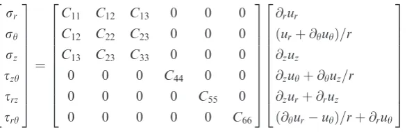
Based on the small deformation assumption, the second order of strain is negligible. Assuming the material of each layer is orthotropic among the coordinate planes, the linear stress–displacement relationships for an arbitrary layer can be expressed as the following matrix form
rr
rh rz
szh
srz srh
2 6 6 6 6 6 6 6 6 6 4
3 7 7 7 7 7 7 7 7 7 5
¼
C11 C12 C13 0 0 0
C12 C22 C23 0 0 0
C13 C23 C33 0 0 0
0 0 0 C44 0 0
0 0 0 0 C55 0
0 0 0 0 0 C66
2 6 6 6 6 6 6 6 6 6 4
3 7 7 7 7 7 7 7 7 7 5
@rur
ðurþ@huhÞ=r @zuz
@zuhþ@huz=r @zurþ@ruz
ð@huruhÞ=rþ@ruh
2 6 6 6 6 6 6 6 6 6 4
3 7 7 7 7 7 7 7 7 7 5
(1)
whereC11,C12,C13,C22,C23,C33,C44,C55,C66are the elastic stiffness coefficients;rr,rh,rzare the radial stress
components;szh, srz,srhare the shear stress components;ur,uh,uzare the displacements components.
qis the mass density. With the absence of body force, the equilibrium equation is given as
@zrzþ
srz
r þ@rsrzþ
@hszh
r q@
2 tuz¼0; @hrh
r þ
2srh
r þ@rsrhþ@zszhq@
2 tuh¼0;
@rrrþ
rrrh
r þ@zsrzþ
@hsrh
r q@
2 tur¼0
(2)
Four different boundaries are set inz¼0 orl. All of them can be written as Clamped (z¼0)–Clamped (z¼l)
at z¼0; ur¼uh¼uz¼0 (3)
[image:3.595.161.461.244.339.2]at z¼l; ur¼uh ¼uz¼0 (4)
Clamped (z¼0)–Simply supported (z¼l)
at z¼0; ur¼uh¼uz¼0 (5)
at z¼l; rz¼ur¼uh¼0 (6)
Clamped (z¼0)–Free (z¼l)
at z¼0; ur¼uh¼uz¼0 (7)
at z¼l; rz¼szh ¼srz¼0 (8)
Simply supported (z¼0)–Simply supported (z¼l)
at z¼0; rz¼ur¼uh¼0 (9)
at z¼l; rz¼ur¼uh¼0 (10)
The boundary conditions at inner (r¼b) and outer (r¼a) surfaces are given as
at inner surface ðr¼bÞ; rr¼frb; srh¼fhb; and srz¼fzb (11)
at outer surface ðr¼aÞ; rr¼fra; srh ¼fha; and srz¼fza (12)
Numerical method
An efficient numerical inversion for Laplace transform
The Laplace transform, which is very efficient in dealing with complex differential equations, is widely used in structural dynamics.37,38To seek a solution to the complicated dynamic problems, Durbin’s34numerical inversion method was proposed which always generates almost the same results as that given by analytical inversion methods in a short time range. The numerical inversion method for Laplace transform can be expressed by the following formula.34
fð*tÞ ¼2 expðat
* Þ
T
~
fðaÞ
2 þ
XK
k¼1
Re f~ðaþkpi=TÞ
h i
cosðkp*t=TÞ
( )
(13)
wherea¼5/T,T¼2Td,Kis a sufficient number, andTdis the observation period.
Differential quadrature method
The function of DQM is to discretise the fundamental equations by turning the partial derivative to polynomials along the z direction. Based on the high-order polynomials, the weighted coefficients of DQM are computed by a
series of mathematical formulation.39 Now, assuming f r~*;*z;*s is a continuous function, the i-th order partial derivative along the zdirection can be expressed by a sum of values in the spatial domain
@if r~*;z* m;s
*
@*zi
¼X
M
n¼1
AðmniÞ~f r*;z*n;*s
(14)
wheremis from 1 to sampling pointsM; nis from 1 toM1;AðiÞ
Semi-analytical solution
According to the stress–displacement relationships and equilibrium differential equations, a semi-analytical method which requires employing the SSM and DQM is proposed to solve the governing equations under various boundary conditions. To obtain the natural frequencies and transient response of the cylindrical panel, the SSM and one-dimensional differential quadrature rule are used to establish a linear eigenvalue system, firstly along the radial direction and then established along the length direction.
Normalization
To simplify the calculation, the variables can be normalised in below
C*ij
r* r r * h r * z s * rh s * zh s * rz 8 > > > > > > > > > > > > > < > > > > > > > > > > > > > : 9 > > > > > > > > > > > > > = > > > > > > > > > > > > > ; ¼ 1 C33 Cij rr rh rz
srh szh
srz 8 > > > > > > > > > > > > < > > > > > > > > > > > > : 9 > > > > > > > > > > > > = > > > > > > > > > > > > ; ; r * z * t * s * u * r u * h u * z 8 > > > > > > > > > > > > < > > > > > > > > > > > > : 9 > > > > > > > > > > > > = > > > > > > > > > > > > ; ¼ 1
a 1l ca ac 1a 1a 1a
n oT
r z t s ur uh uz 8 > > > > > > > > > > > > < > > > > > > > > > > > > : 9 > > > > > > > > > > > > = > > > > > > > > > > > > ; T (15)
wherei,j¼1,2,. . .,6, andcis the wave velocity.
c¼ðC33=qÞ1=2 (16)
To separate the variableh, Fourier series are employed to expand the displacement and stress components into a form of trigonometric function.32The wave number isj, the panel’s sector angle isa.
r*rð
r
* ;h;z*;tÞ
u
*rð
r
* ;h;*z;tÞ
u
*
hð*r;h;z*;tÞ
u
* zðr
* ;h;z*;tÞ s
*
rzð*r;h;*z;tÞ
s
* rhðr
* ;h;z*;tÞ r
*
hð*r;h;*z;tÞ
r
*zð
r
* ;h;z*;tÞ s
*
zhð*r;h;*z;tÞ
8 > > > > > > > > > > > > > > > > > > > > > > > > < > > > > > > > > > > > > > > > > > > > > > > > > : 9 > > > > > > > > > > > > > > > > > > > > > > > > = > > > > > > > > > > > > > > > > > > > > > > > > ;
¼X1 j¼0
rrð*r;*z;tÞsinðjph=aÞ
urð*r;*z;tÞsinðjph=aÞ
uhð*r;z*;tÞcosðjph=aÞ
uzðr *
;*z;tÞsinðjph=aÞ
srzð*r;*z;tÞsinðjph=aÞ
srhðr *
;z*;tÞcosðjph=aÞ
rhð*r;*z;tÞsinðjph=aÞ
rzð*r;*z;tÞsinðjph=aÞ
szhð*r;z*;tÞcosðjph=aÞ
8 > > > > > > > > > > > > > > > > > > > > > > > > < > > > > > > > > > > > > > > > > > > > > > > > > : 9 > > > > > > > > > > > > > > > > > > > > > > > > = > > > > > > > > > > > > > > > > > > > > > > > > ; (17)
By substituting equations (1) and (2), governing equation can be obtained in the form of state space approach. After employing the Fourier expansion and Laplace transform, the fundamental equations are derived as
dr~r
d r! ¼ q ! s !2
þg2
r !2
~
urþag3 lr @
~
u
@!z jpg2uh~
a!r2
g1rr
r
!
a@s~rz
l@!z þ jps~rh
a!r
du~r
d r! ¼
~ rr C ! 11 C ! 12 C !
11!r ~
urþ
jpC!12
a!rC!11 ~
uhaC !
13
lC!11 @u~z
duh~ d r! ¼
jpu~r
a!r þ
~
uh r ! þ ~
srh
C !
66
du~z
d r! ¼ a@u~r
l@!z þ
~
srz
C !
55
ds~rz
d r! ¼ ag3@u~r
l r!@!z þ q ! s !2
a2g4@2
l2@!z2 þ
j2p2C! 44
a2!r2
!
~
uzþaj
pg5@uh~ lar!
aC!13@r~r
lC!11@!z s~rz
r !
ds~rh
d r! ¼ jpg2u~r
a!r2
þajpg5@u~z
la!r@!z þ q ! s !2
a2C
!
44@2
l2@!z2 þ
j2p2!g 2
a2!r2
!
~
uhjpC !
12r~r
a!rC!11 2s~rh
r !
(18)
where
g1¼1C
* 12
C*11
; g2¼C*22
C*
2 12
C*11
; g3¼C*23
C*12C * 13
C*11
; g4¼C*33
C*
2 13
C*11 ;
g5 ¼ C*12C *
13þC *
11 C *
23þC * 44
h i
=C*11
(19)
The other three variables can be determined by
~
rh¼g2 r
*u~rþ
ag3 l
@u~z @z*
jpg2 ar* uh~ þ
C*12
C*11 ~
rr;
~
rz¼
g3 r
*u~rþ
ag4 l
@u~z @z*
jpg3 ar* uh~ þ
C*13
C*11 ~
rr;
~
szh¼jpC
* 44
ar* u~zþ
aC*44
l
@uh~ @z*
(20)
As M is the sum of sample points,m-th is the location of calculating the sample point. By applying DQM on equations (18) and (20), the new state space equations can be rewritten as shown below
dr~rm dr* ¼
a l
XM
n¼1
Að Þmn1 s~rznþag3 lr*
XM
n¼1
Að Þmn1u~znþ *s2q*þg2 r
*2
~
urm
jpg2uh~m
ar*2 g1 ~
rrm r
* þ
jps~rhm
ar* ;
du~rm dr* ¼
~
rrm C*11
C
* 12
r
*
C*11 ~
urmþjpC
* 12
ar*
C*11 ~
uhm
aC*13
lC*11
XM
n¼1
Að Þmn1u~zn;
duh~m
d*r ¼ jp
~
urm ar* þ
~
uhm
r
* þ ~
srhm
du~zm
dr* ¼ a
l
XM
n¼1
Að Þmn1u~rnþs~rzm C*55 ;
ds~rzm dr* ¼
ag3 lr*
XM
n¼1
Að Þmn1u~rna
2g 4
l2
XM
n¼1
Að Þmn2u~znþajpg5 lar*
XM
n¼1
Að Þmn1uh~n
s~rzm
r
*
aC*13
lC*11
XM
n¼1
Að Þmn1r~rnþ *s2q*þj
2p2C* 44
a2*r2
!
~
uzm;
ds~rhm
dr* ¼ ajpg5
lar*
XM
n¼1
Að Þmn1u~znjpg2u~rm ar*2 þ s
*2q*þj2p2g2
a2*r2
!
~
uhm
2s~rhm
r
*
jpC*12
ar*
C*11 ~
rrma2C * 44
l2
XM
n¼1
Að Þmn2uh~n
(21)
For them-th sample point, the other three variables can be determined by
~
rhm¼
ag3 l
XM
n¼1
Að Þmn1u~znþg2u~rm r
*
jpg2uh~m
ar* þ
C*12
C*11 ~
rrm;
~
rzm¼ag4
l
XM
n¼1
Að Þmn1u~znþg3u~rm r
*
jpg3uh~m
ar* þ
C*13
C*11 ~
rrm;
~
szhm¼
aC*44
l
XM
n¼1
Að Þmn1uh~nþ
jpC*44
ar* u~zm
(22)
To apply the DQM, Laplace transform and Fourier series on equations (3) to (10), the cylindrical panel’s boundary conditions are given as
C-C
z¼0; u~r1¼uh~1¼u~z1¼0 (23)
z¼l; u~rM¼uh~M¼u~zM¼0 (24)
C-S
z¼0; u~r1¼uh~1¼u~z1¼0 (25)
z¼l; r~zM¼uh~M¼u~rM¼0 (26)
C-F
z¼0; u~r1¼uh~1¼u~z1¼0 (27)
z¼l; r~zM¼s~zhM ¼s~rzM¼0 (28)
S-S
z¼0; r~z1¼uh~1¼u~r1¼0 (29)
Similarly, for the inner and outer surface, the transformed boundaries are derived as
r¼b; ~rrb¼~frb; ~srhb¼~fhb; and ~srzb ¼~fzb (31)
r¼a; ~rra¼~fra; ~srha¼~fha; and ~srza ¼~fza (32)
wherer~rb ¼fr~r1;. . . ~rrMgr¼bT,f~ha ¼f~fh1;. . . ~fhMgr¼aT,. . .
Semi-analytical solution
As shown in equation (21), the differential equation with so many variables is too complex to be solved by analytical approaches. Hence, for the sake of simplification, an approximate method is performed by introducing a radial local coordinatenk, an approximationnk/Rk1 is considered as a thin cylindrical panel in each layer.nkis
located at the centre ofk-th layer.40
1 r
*¼
1kk
ð Þ
Rk ;
1 r
*¼
12kk
ð Þ
R2 k
(33)
where nk¼rRk and kk¼nk/Rk. According to the assumption, kk can be neglected. Hence, equation (21) is
supposed to be derived by the form of matrix
dQ~ðkÞ
dk ¼HQ~ðkÞ (34)
whereQ~¼ fr~r;~ur;u~h;~uz;~srz;~srhg,r~r ¼ fr~r1;. . . ~rrMgT,u~r ¼ fu~r1;. . . ~urMgT,. . .The constitution of matrix Hcan
be found in Appendix 1. After applying different boundary conditions to the equations (23) to (30), the variousH is given in Appendix 2.
The expression of equation (34) is supposed to be
~
QðkÞ ¼exp½Hkðkkk1Þ Q~ðkk1Þ: h 2Rk
k h
2Rk
(35)
Equation (35) at k¼kkyields
~
QðkkÞ ¼expðHhkÞ Q~ðkk1Þ (36)
wherehkis the thickness ofk-th layer.
Subsequently
~
Qðkkþ1Þ ¼expðHkþ1hkþ1Þ Q~ðkkÞ ¼expðHkþ1hkþ1Þ expðHkhkÞ Q~ðkk1Þ (37)
For allKlayers have the same behaviour, the FGM cylindrical panel’s state vectors at the outer surface can be determined by the inner surface
~
Q bð Þ ¼TðabÞ Q a~ð Þ (38)
where
Tð Þ ¼h Y
1
k¼K
expðHkhkÞ (39)
Tð Þ¼h Tij
66
At the outer and inner surfaces, the boundaries equations (31) and (32) are applied into equation (38)
~
fr ~
fz ~fh
8 > < > :
9 > = > ;
r¼b
¼ TT1151 TT1252 TT1353
T61 T62 T63
T14 T15 T16
T54 T55 T56
T64 T65 T66
2 4
3 5
~
fr ~
ur ~
uh
~
uz ~fz ~
fh
8 > > > > > > > < > > > > > > > :
9 > > > > > > > = > > > > > > > ;
r¼a
(41)
where
~
fr¼ f~r1;. . .;~frM
n oT
; ~fz¼ f~z1;. . .;f~zM
n oT
; ~fh¼ ~fh1;. . .;f~hM
n oT
Numerical results
Firstly, compared with data obtained by other theoretical methods, the natural frequencies of a clamped FGM cylindrical panel are investigated for different functionally graded indexc.Subsequently, the displacements along rdirection obtained by the proposed method are compared with FEM to validate the proposed method. And then, the research regarding convergence are carried out for different cases. In conclusion, this allows the effects of cylindrical panel’s geometric size and functionally graded indexcto be investigated.
Nature frequencies study
In comparison with previous results in literature,41,42the natural frequencies of the FGM cylindrical panel are investigated (Figure 2). The geometric size of the cylindrical panel isL/h¼10,L/b¼0.1 with clamped boundary condition varies in the functionally graded indexc. Andxis its chord length. The material properties of this FGM panel are stainless steel (SUS304) and silicon nitride (Si3N4). The constituents of the two kind of material are
described in Table 1.
In Table 2, non-dimensional frequency parameter is given by x¼xl2 ffiffiffiffiffiffiffiffiffiffiffiffiffiffiffiffiffiq mh=Dm
p
in which
Dm¼Emh3=12ð1l2 mÞ.
The purpose of free vibration analysis is to validate the reliability of the proposed approach. As we know, the boundary conditions, wave number and geometric size are the main factors to decide the values of natural
frequency. In this section, the boundary condition is simply supported and wave numberiis equal to 1. The results of the first mode frequencies are shown in Table 2 for different functionally graded index calong with those of Yang and Shen42and Pradyumna and Bandyopadhyay.41It is indicated that the values obtained by the proposed method agree with Yang and Shen’s42 and Pradyumna and Bandyopadhyay’s41methods.
Transient responses study
In order to further demonstrate the accuracy of the proposed approach, its displacements along therdirection are compared with the results by commercial software ANSYS. The cases with various variables are given in Table 3. For the orthotropic properties, the stiffness coefficient and mass density are supposed to change following the variation law along therdirection. By applying exponential law, the material properties can be expressed as
fCij;qg ¼ fC^ij;^qg exp cðarÞ=ðabÞ (42)
In our studies and experiment, the material properties of this FGM panel are made up with zirconia and aluminium. Moreover, the distribution of volume fractions along the radial direction obeyed the power laws can be defined as
VCð Þ ¼r ðarÞ=ðabÞ
c
;
VAð Þ ¼r 1 ðarÞ=ðabÞ
c (43)
Here, A means aluminium and C represents ceramic zirconia. Therefore, the material properties of this FGM cylindrical panel are derived as
fCij;qg ¼ fCij;C;qCgVCð Þ þ fr Cij;A;qAgVAð Þr (44)
[image:10.595.96.487.86.145.2]The fundamental material properties in this paper are shown in Table 4. Table 1. FGM cylindrical panels’ parameters.41
Constituent
Elastic modulus
E(GPa)
Poisson’s ratio l
Mass density q(kg/m3)
SUS304 (metal) 207.7877 0.31776 8166
[image:10.595.96.486.179.248.2]Si3N4(ceramic) 322.2715 0.24 2370
Table 2. Natural frequencies of the first mode for FGM cylindrical panels.
c Yang and Shen42
Pradyumna and
Bandyopadhyay41 Proposed method
0 74.518 72.9613 73.8433
0.2 57.479 60.0269 59.6093
2 40.750 39.1457 39.0261
Table 3. Cases with different variables and boundaries.
Case number
Variation law of material properties
central anglea
FG index c
Load parameterj
Length
l(m)
Outer Radius
a(m)
Width
b(m)
Boundary conditions atz¼0,l
1 Exponential 30 5 3 1 1 0.98 C-C
2 Exponential 45 0.2 1 2 1 0.98 C-F
3 Power 90 0.5 3 0.7 1 0.98 C-S
[image:10.595.51.534.291.382.2]Then the distribution properties of each layer can be defined as
fCij;qgk¼
Z zk
zk1
fCij;qgðrÞdr rkrk1
(45)
wherek¼1,2,. . .,K.
The force applying to the outer surface (r¼a) of the cylindrical panel is given as31
at r¼a; rr¼103C33;Asin
jp ah
expðtcA=lÞ (46)
wherecA¼ C33;A=qA
1=2
is the longitudinal wave velocity of aluminium.44
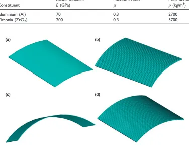
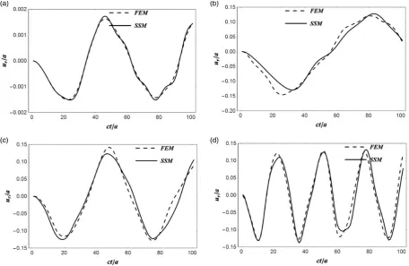
At first, the layer number K and sampling point M are 4 and 21, respectively. The finite element models established by software ANSYS are given in Figure 3. Solid 64 of the structure elements are used in the finite element analysis. The central position (r¼(aþb)/2,h¼0,z¼l/2) is chosen to calculate the results. In Figure 4, the numerical results between the proposed approach and FEM are compared with each other. It is shown that the results predicted by the two methods agree with each other. Compared with ANSYS, the method has a higher computational efficiency in calculating the transient response of the cylindrical panel, and relevant data can be found in Table 5. Moreover, the numerical solutions are independent from conditions determined by geometry, FG index and other boundary conditions.
Convergence studies
[image:11.595.115.492.97.387.2]The importance of convergence studies lies in their purpose of clarifying the effects of different factors. And the condition which is used to carry out the research is the same as the conditions put in place for case 4 in Table 3. Figure 3. FE models of (a) case 1, (b) case 2, (c) case 3, and (d) case 4.
Table 4. Fundamental material properties.43
Constituent
Elastic modulus
E(GPa)
Poisson’s ratio l
Mass density q(kg/m3)
Aluminium (Al) 70 0.3 2700
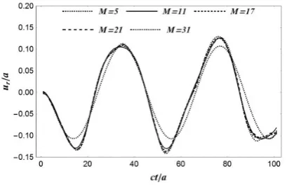
Firstly, a series of sampling points are used to analyse the convergence rate along thez- direction. The values of Mare 5, 11, 17, 21 and 31, respectively. The relation between the normalised deflectionur/aand time history at
central position are shown in Figure 5. It is indicated that, the more sampling point numbers, the more accurate the results will be. When the numbers of sampling points are at a relatively large level, the results do not change much. It also displays that the proposed method converges fast with the increasing sampling points.
Secondly, a series of layer numbers are employed in order to analyse the convergence rate along the r direction. The values of K are 2, 4, 8 and 12, respectively. The relation between the normalised deflection ur/a and time
history at central position are shown in Figure 6. It is indicated that the cases withKare larger than 4 and have nearly the same results. Therefore, the proposed approach has a high convergence rate with the change of layer numbers.
Effects of l/a and (ab)/a
[image:12.595.64.521.73.370.2]To study the effects of l/aand (a-b)/a, the deflection along the radial direction of FGM cylindrical panels are examined here. The sampling point number and the layer number are 21 and 4 respectively. Also, the condition which is used to carry out the researches is the same as case 4 in Table 3.
Figure 4. Deflection history: (a) case 1; (b) case 2; (c) case 3; (d) case 4.
Table 5. Time required for calculating the dynamic response of the FGM cylindrical panel.
Methods NSP 1 2 3 Average time (s)
Proposed method 5 68.234 69.375 69.156 68.922
11 162.154 139.295 179.751 160.4
21 402.031 423.969 475.75 433.917
31 879.189 967.252 974.125 940.189
ANSYS / 1323.000 1293.688 1295.516 1304.068
[image:12.595.49.538.434.514.2]Firstly, the effect of the length/outer radius ratio (l/a) is investigated. A series ofl/a¼1, 1.2, 1.6, and 2 are used here. The relation between the normalised deflectionur/aand time history at the central position are shown in
Figure 7. It shows that the deflection of FGM cylindrical panels increases as length/outer radius ratio l/a increases. The reason is that the flexibility of the whole structure becomes greater when the ratio increases. Thus, the cylindrical panel deforms easier under the same external force, and the vibration period will also be longer.
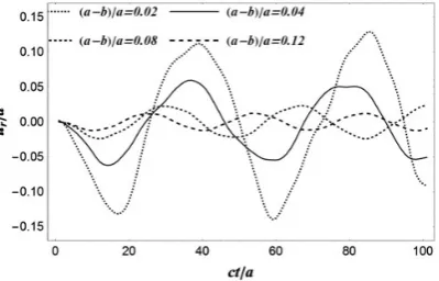
Secondly, the effect of the thickness/outer radius ratio (a-b)/ais studied. A series of (a-b)/a¼0.02, 0.04, 0.08 and 0.16 is employed here. Both the length and outer radius are fixed to be 1 m. The relation between the normalised deflection ur/a and time history at central position are plotted in Figure 8. As indicated in the
[image:13.595.204.409.75.207.2] [image:13.595.205.406.253.382.2]figure, the deflection shows a trend that is actually opposite to what is observed with the thickness/outer Figure 5. Deflection history with different numbers of sampling points.
[image:13.595.205.406.427.565.2]Figure 6. Deflection history with different layer numbers.
radius ratio. When the ratio increases, the deflection actually decreases. Because, on the one hand, the structural flexibility will become less with the increase of thickness, and on the other hand, the bearing capacity of the structure is strengthened with the increase of thickness. So that it can resist external force more effectively, and the vibration period will also be shortened.
Effect of FG index
To study the effects of FG indexc, the deflection along the radial direction of FGM cylindrical panel is examined here. The sampling point number and the layer number are 21 and 4, respectively. Furthermore, the condition which is used to carry out the research is the same as case 4 in Table 3.
In this section, the paper has studied two different variation laws. On the one hand, the power variation law means that the fundamental properties distribute in a power law. On the other hand, the exponential variation law assumes the fundamental properties distribute in an exponential law. And both of them employed various FG parameters c¼0.2, 0.5, 2 and 5 in this FGM cylindrical panel.
Two different variation laws show distinct differences on the transient response of FGM cylindrical panels at central position in Figure 9. In terms of exponential variation law, the deflection of the panel decreases as functionally graded index cincreases. But for the FGM panel with a power variation law, the deflection of the panel increases as functionally graded indexcincreases. It is because the smaller value of FG index is, the more uniform the volume fraction becomes, which leading to the higher structural strength and weaker vibration response. However, the result of the exponential law is on the contrary.
CNT-reinforced FGM
The discovery of CNT has been a great breakthrough in many applications.45,46 Due to their superior mechanical, electrical and chemical properties, CNT can be utilized to strengthen composite materials. In this section, the uniform distribution of CNT is taken into consideration to improve the ability of resisting the FGM cylindrical panel’s vibration. The condition which is used to carry out the research is the same as case 3 in Table 3, but the time domain is different. The single-wall CNT (SWCNT) material properties are assumed to be qCNT¼1400 kg/m3, lCNT¼0.175, ECNT¼5.6466 TPa. The volume fraction of CNT for the
FGM cylindrical panel is assumed to be VCNT. The SWCNT uniformly distributed along the thickness
direction of the composite cylindrical panel can be depicted in Figure 10. The relationship between VCNT
and VFGM should satisfy with
VCNTþVFGM¼1 (47)
[image:14.595.194.394.74.202.2]The comparison of FGM and CNT-reinforced FGM at the central position is shown in Figure 11. Besides, four boundary conditions in this circumstance are also depicted.
Figure 10. Uniform distribution of CNT.
Figure 9. Deflection history with different variation law: (a) power law; (b) exponential law.
[image:15.595.208.402.587.709.2]Figure 11 indicates that SWCNT greatly enhances the mechanical characteristics of FGM and strengthens the ability of composite structure to resist external force. As shown in Figure 12, clamp-clamp condition gives the smallest deflection in these four boundary conditions.
Conclusions
To analyse the dynamic vibration of FGM cylindrical panels under different boundaries, a 3D semi-analytical method is proposed by introducing the Durbin’s numerical inversion method, state space approach, and differ-ential quadrature method. Compared with many numerical methods, the semi-analytical results in this paper have higher accuracy, because there are fewer errors and limitations caused by the introduction of stress and displace-ment assumptions.
To compare the proposed approach with other theoretical methods from the literature, the natural frequencies show consistent results. Especially, the reliable comparative verification of transient response produced by the proposed method and FEM on different boundary conditions is presented. Convergence studies indicate that the proposed method has a quick convergence rate with growing sample point numbers along the length direction and layer numbers along the radial direction. For the study of different length/outer radius ratio, the flexibility of the whole structure becomes greater when the ratio increases. Thus, the cylindrical panel deforms easier under the same external force, and the vibration period will also become longer. The effect of thickness/outer radius ratio is also studied. The increase of thickness can resist external force more effectively, and the vibration period will also be shortened. The results compared with the power law and exponential law show completely different. To combine this characteristic with engineering, FGM can be designed to meet complex circumstances and optimize the structural performance. When the uniform distribution of CNT is added to FGM cylindrical panel, the mechanical properties of composite structure have been reinforced greatly. The proposed 3D semi-analytical method has high accuracy for the analysis of composite structures and can be used to study the behaviour of functionally graded porous material in the further research. This study can serve as a foundation for solving more complicated problems such as fluid–structure interaction of flexible pipe or thermal effect analysis of FGM in aerospace field.
Declaration of conflicting interests
The author(s) declared no potential conflicts of interest with respect to the research, authorship, and/or publication of this article.
Funding
The author(s) disclosed receipt of the following financial support for the research, authorship, and/or publication of this article: This work was supported by the National Natural Science Foundation of China (Grant no. 51879231, 51679214, 51409228).
ORCID iD
[image:16.595.198.389.72.196.2]Xue Jiang https://orcid.org/0000-0001-9860-8580 Yongdu Ruan https://orcid.org/0000-0003-4849-2924
References
1. Rajasekaran S and Khaniki HB. Finite element static and dynamic analysis of axially functionally graded nonuniform small-scale beams based on nonlocal strain gradient theory.Mech Adv Mater Struct2018; 7: 1–15.
2. Fu Y, Yao J, Wan Z, et al. Free vibration analysis of moderately thick orthotropic functionally graded plates with general boundary restraints.Materials2018; 11: 273.
3. Sarvestani HY, Akbarzadeh AH and Mirabolghasemi A. Structural analysis of size-dependent functionally graded doubly-curved panels with engineered microarchitectures.Acta Mech2018; 229: 2675–2701.
4. Kieback B, Neubrand A and Riedel H. Processing techniques for functionally graded materials.Mater Sci Eng A2003; 362: 81–106.
5. Li L, Li X and Hu Y. Free vibration analysis of nonlocal strain gradient beams made of functionally graded material.Int J Eng Sci2016; 102: 77–92.
6. Parida S and Mohanty SC. Free vibration and buckling analysis of functionally graded plates resting on elastic foundation using higher order theory.Int J Struct Stabil Dynam2018; 18: 21.
7. Cheng ZQ and Batra RC. Deflection relationships between the homogeneous Kirchhoff plate theory and different func-tionally graded plate theories.Arch Mech2008; 52: 143–158.
8. Frikha A and Dammak F. Geometrically non-linear static analysis of functionally graded material shells with a discrete double directors shell element.Comput Methods Appl Mech Eng2017; 315: 1–24.
9. Yaghoubshahi M, Asadi E and Fariborz SJ. A higher-order shell model applied to shells with mixed boundary conditions.
Proc Inst Mech Eng C J Mech Eng Sci2011; 225: 292–303.
10. Quan TQ and Duc ND. Nonlinear vibration and dynamic response of shear deformable imperfect functionally graded double-curved shallow shells resting on elastic foundations in thermal environments. J Therm Stresses 2016; 39: 437–459.
11. Mantari JL, Oktem AS and Soares CG. Static and dynamic analysis of laminated composite and sandwich plates and shells by using a new higher-order shear deformation theory.Compos Struct2012; 94: 37–49.
12. Liang X, Wang Z, Wang L, et al. Semi-analytical solution for three-dimensional transient response of functionally graded annular plate on a two parameter viscoelastic foundation.J Sound Vib2014; 333: 2649–2663.
13. Fan J and Ye J. An exact solution for the statics and dynamics of laminated thick plates with orthotropic layers.Int J Solids Struct1990; 26: 655–662.
14. Zeng QC, Lim CW, L~a CF, et al. Asymptotic two-dimensional elasticity approach for free vibration of FGM circular arches.Mech Compos Mater Struct2012; 19: 29–38.
15. Xu RQ. Three-dimensional exact solutions for the free vibration of laminated transversely isotropic circular, annular and sectorial plates with unusual boundary conditions.Arch Appl Mech. 2008; 78: 543–558.
16. Tahouneh V and Yas MH. Semianalytical solution for three-dimensional vibration analysis of thick multidirectional functionally graded annular sector plates under various boundary conditions. J Eng Mech 2013; 140: 31–46.
17. Alibeigloo A, Kani AM and Pashaei MH. Elasticity solution for the free vibration analysis of functionally graded cylin-drical shell bonded to thin piezoelectric layers.Int J Pres Ves Pip2012; 89: 98–111.
18. Alibeigloo A and Simintan V. Elasticity solution of functionally graded circular and annular plates integrated with sensor and actuator layers using differential quadrature.Compos Struct2011; 93: 2473–2486.
19. Nie GJ and Zhong Z. Vibration analysis of functionally graded annular sectorial plates with simply supported radial edges.
Compos Struct2008; 84: 167–176.
20. Eroglu U. Large deflection analysis of planar curved beams made of functionally graded materials using variational iterational method.Compos Struct2016; 136: 204–216.
21. Kanani AS, Niknam H, Ohadi AR, et al. Effect of nonlinear elastic foundation on large amplitude free and forced vibration of functionally graded beam.Compos Struct2014; 115: 60–68.
22. Wu CP and Tsai YH. Cylindrical bending vibration of functionally graded piezoelectric shells using the method of perturbation.J Eng Math2009; 63: 95.
23. Lian Y, He X, Shi S, et al. A multi-parameter perturbation solution for functionally graded piezoelectric cantilever beams under combined loads.Materials2018; 11: 1222.
24. Odibat Z and Momani S. Analytical comparison between the homotopy perturbation method and variational iteration method for differential equations of fractional order.Int J Mod Phys B2008; 22: 4041–4058.
25. Huang Y and Huang Y. A real-time transient analysis of a functionally graded material plate using reduced-basis methods.
ALAMT2015; 5: 98–108.
26. Zhou FX, Li SR and Lai YM. Three-dimensional analysis for transient coupled thermoelastic response of a functionally graded rectangular plate.J Sound Vib2011; 330: 3990–4001.
27. Nezhadi A, Rahman RA and Ayob A. Transient analysis of functionally graded cylindrical shell under impulse local loads.
Aust J Basic Appl Sci2011; 5: 757–765.
29. Malekzadeh P, Heydarpour Y, Haghighi MRG, et al. Transient response of rotating laminated functionally graded cylindrical shells in thermal environment.Int J Pres Ves Pip2012; 98: 43–56.
30. Selahi E, Setoodeh AR and Tahani M. Three-dimensional transient analysis of functionally graded truncated conical shells with variable thickness subjected to an asymmetric dynamic pressure.Int J Pres Ves Pip2014; 119: 29–38.
31. Liang X, Kou HL, Liu GH, et al. A semi-analytical state-space approach for 3D transient analysis of functionally graded material cylindrical shells.J Zhejiang Univ Sci A2015; 16: 525–540.
32. Liang X, Kou HL, Wang L, et al. Three-dimensional transient analysis of functionally graded material annular sector plate under various boundary conditions.Compos Struct2015; 132: 584–596.
33. Liang X, Wu Z, Wang L, et al. Semianalytical three-dimensional solutions for the transient response of functionally graded material rectangular plates.J Eng Mech2014; 141: 04015027.
34. Durbin F. Numerical inversion of Laplace transforms: an efficient improvement to Dubner and Abate’s method.Comp J
2013; 17: 371–376.
35. Chen M, Li S, Li H, et al. New analytic method for free torsional vibration analysis of a shaft with multiple disks and elastic supports.Arch Appl Mech2018; 88: 955–979.
36. Li H, Pang F, Wang X, et al. Free vibration analysis for composite laminated doubly-curved shells of revolution by a semi analytical method.Compos Struct2018; 201: 86–111.
37. Cohen AM.Numerical methods for Laplace transform inversion. New York: Springer, 2007.
38. Wang Z, Liang X, Fallah AS, et al. A novel efficient method to evaluate the dynamic response of laminated plates subjected to underwater shock.J Sound Vib2013; 332: 5618–5634.
39. Malekzadeh P and Ghaedsharaf M. Three-dimensional thermoelastic analysis of finite length laminated cylindrical panels with functionally graded layers.Meccanica2014; 49: 887–906.
40. Alibeigloo A and Shakeri M. Elasticity solution for static analysis of laminated cylindrical panel using differential quad-rature method.Eng Struct2009; 31: 260–267.
41. Pradyumna S and Bandyopadhyay JN. Free vibration analysis of functionally graded curved panels using a higher-order finite element formulation.J Sound Vib2008; 318: 176–192.
42. Yang J and Shen HS. Free vibration and parametric resonance of shear deformable functionally graded cylindrical panels.
J Sound Vib2003; 261: 871–893.
43. Hasheminejad SM and Gheshlaghi B. Three-dimensional elastodynamic solution for an arbitrary thick FGM rectangular plate resting on a two parameter viscoelastic foundation.Compos Struct2012; 94: 2746–2755.
44. Liang X, Wang Z, Wang L, et al. A semi-analytical method to evaluate the dynamic response of functionally graded plates subjected to underwater shock.J Sound Vib2015; 336: 257–274.
45. Selim BA, Zhang LW and Liew KM. Vibration analysis of CNT reinforced functionally graded composite plates in a thermal environment based on Reddy’s higher-order shear deformation theory. Compos Struct 2016; 156: 276–290.
46. Zhang LW and Selim BA. Vibration analysis of CNT-reinforced thick laminated composite plates based on Reddy’s higher-order shear deformation theory.Compos Struct2017; 160: 689–705.
Appendix 1
H¼
g1IM
R H12
jpg2IM
R2a
ag3Að Þ1 mn
Rl
aAð Þmn1 l
jpIM
Ra IM
C*11
H22 H23 H24 0 0
0 jpRaIM IM
R 0 0
IM
C*66
0 aA
1
ð Þ
mn
l 0 0
IM
C*55
0
H51
ag3Að Þ1 mn
Rl H53 H54 IM
R 0
H61
jpg2IM
R2a H63 H64 0
2IM
R
2 6 6 6 6 6 6 6 6 6 6 6 6 6 6 6 6 6 6 6 6 6 6 6 6 6 4
3 7 7 7 7 7 7 7 7 7 7 7 7 7 7 7 7 7 7 7 7 7 7 7 7 7 5
whereg6¼q**s2þg2
R2;g7¼q *
s
*2þj2p2C* 44
R2a2 ;g8¼q *
s
*2þj2p2g 2 R2a2 and
H51 ¼
aC*13Að Þmn1
lC*11
; H61 ¼
jpC*12IM
RaC*11
; H12 ¼ q**s 2
þg2
R2
IM;
H22 ¼
C*12IM
RC*11
; H23¼
jpC*12IM
RaC*11
; H53¼
jpag5Að Þ1 mn
Rla ;
H63 ¼ q**s 2
þj2p2g2
R2a2
IM
a2C* 44Að Þmn2
l2 ; H24¼
aC*13Að Þmn1
lC*11 ;
H54 ¼ q**s 2
þj2p2C * 44
R2a2
! IM
a2g4Að Þmn2
l2 ; H64 ¼
jpag5Að Þ1 mn
Rla
IM¼
1 0 0
0 1 0
... ... ... ...
0 0 1
2 6 6 6 6 6 4 3 7 7 7 7 7 5
MM
; and AðmniÞ ¼
Að Þ11i Að Þ12i Að Þ1iM
Að Þ21i Að Þ22i Að Þ2iM
... ... ... ...
Að ÞMi1 Að ÞMi2 Að ÞMMi
2 6 6 6 6 6 6 4 3 7 7 7 7 7 7 5
Appendix 2
(C-C) H¼g1I2
R H12
jpg2I2
R2a
ag3Að Þ1 mn
lR
aAð Þmn1 l
jpI2
Ra I2
C*11
H22 H23 H24 0 0
0 jpI2
Ra
I2
R 0 0
I2
C*66
0 aA
1
ð Þ
mn
l 0 0
I2
C*55
0
H51 H52 H53 H54 I2
R 0
H61
jpg2I2
R2a H63 H64 0
2I2
R 2 6 6 6 6 6 6 6 6 6 6 6 6 6 6 6 6 6 6 6 6 6 6 6 4 3 7 7 7 7 7 7 7 7 7 7 7 7 7 7 7 7 7 7 7 7 7 7 7 5 (49) where
H51¼
aC*13Að Þmn1
lC*11
; H61 ¼
jpC*12I2
RaC*11
; H12 ¼ q**s 2
þg2
R2
I2
a2C* 55Að Þ11nA
1
ð Þ
m1
l2
a2C*
55Að ÞmM1 Að ÞMn1
l2 ;
H22¼
C*12I2
RC*11
; H52 ¼
ag3Að Þ1 mn
lR ; H23¼
jpC*12I2
RaC*11 ; H53¼
jpa g3þC*44
Að Þ1 mn
lRa
H63¼ q*s* 2
þj2p2g2
R2a2
I2
a2C* 44Að Þmn2
l2 ; H24¼
aC*13Að Þmn1
lC*11
; H64¼
jpa g3þC*44
Að Þ1 mn
H54¼ q**s 2
þj2p2C * 44
R2a2
! I2
a2C*2 13A
1
ð Þ
MnAð ÞmM1
l2C* 11
a2 C *2
13A 1
ð Þ
m1A 1
ð Þ
1n þC *
11g4Að Þmn2
l2C* 11
;
I2¼
1 0 0
0 1 0
... ... ... ...
0 0 1
2 6 6 6 6 6 4 3 7 7 7 7 7 5
M2M2
;and m;n¼2M2. . .
(C-S)
H¼
g1I2
R H12
jpg2I2
R2a
ag3Að Þ1 mn
lR
aAð Þmn1 l
jpI2
Ra I2
C*11
H22 H23 H24 0 0
0 jpI2
Ra I
2
R 0 0
I2
C*66
0 aA
1
ð Þ
mn
l 0 0
I1
C*55
0
H51 H52 H53 H54 I1
R 0
H61
jpg2I2
R2a H63 H64 0
2I2
R 2 6 6 6 6 6 6 6 6 6 6 6 6 6 6 6 6 6 6 6 6 6 6 4 3 7 7 7 7 7 7 7 7 7 7 7 7 7 7 7 7 7 7 7 7 7 7 5 (50) where
H51 ¼
aC*13Að Þmn1
lC*11
; m¼1M1; n¼2M1; H61¼
jpC*12I2
RaC*11
; m;n¼2M1;
H12 ¼ q**s 2
þg2
R2
I2
a2C*55Að ÞmM1 Að ÞMn1
l2 ; m;n¼2M1; H22¼
C*12I2
RC*11
; m;n¼2M1;
H52 ¼
ag3Að Þ1 mn
lR ; m¼1M1; n¼2M1; H23¼
jpC*12I2
RaC*11
; m;n¼2M1;
H53 ¼
jpa g3þC*44
Að Þ1 mn
lRa ; m¼1M1; n¼2M1;
H63 ¼ q *
s
*2
þj2p2g2
R2a2
I2
a2C* 44Að Þmn2
l2 ; m;n¼2M1;
H24 ¼
aC*13Að Þmn1
lC*11
; m¼2M1; n¼1M1;
H64 ¼
jpa g3þC*44
Að Þ1 mn
lRa ; m¼2M1; n¼1M1;
H54 ¼ q *
s
*2
þj2p2C * 44
R2a2
! I1þ
a2g4 A1
ð Þ
1nA 1
ð Þ
m1A2
ð Þ
mn
l2
a2C*2 13A
1
ð Þ
mMAð ÞMn1
l2C* 11
: m;n¼1M1;
I1 ¼
1 0 0
0 1 0
... ... ... ...
0 0 1
2 6 6 6 4 3 7 7 7 5
(C-F)
H¼
g1I2
R H12 H13 H14
aAð Þmn1 l
jpE8
Ra G5
C*11
H22 H23 H24 0 0
0 jpI1
Ra I
1
R 0 0
I1
C*66
0 aA
1
ð Þ
mn
l 0 0
I2
C*55
0
H51 H52 H53 H54 I2
R 0
H61
jpg2I1
R2a H63 H64 0
2I1
R 2 6 6 6 6 6 6 6 6 6 6 6 6 6 6 6 6 6 6 6 6 6 6 6 6 6 4 3 7 7 7 7 7 7 7 7 7 7 7 7 7 7 7 7 7 7 7 7 7 7 7 7 7 5 (51) where
H51 ¼
aC*13Að Þmn1
lC*11
; m;n¼2M1; H61¼
jpC*12G5
RaC*11
; m¼1M1; n¼2M1;
H12 ¼ q**s 2
þg2
R2
E8
a2C*55Að ÞmM1 Að ÞMn1
l2 ; m¼2M1; n¼1M1;
H22 ¼
C*12I1
RC*11
; m;n¼1M1; H52 ¼
ag3Að Þ1 m1
lR
ag3Að Þ1 mn
lR ; m¼2M1; n¼1M1;
H13 ¼
jpg2E8
R2a
aa2g 3A
1
ð Þ
1nA 1
ð Þ
m1
l2jp ; m¼2M1;n¼1M1;
H23 ¼
jpC*12I1
RaC*11
þRaa2C *
13Að Þ11nA 1
ð Þ
m1
l2jpC* 11
; m;n¼1M1;
H53 ¼
jpag3Að Þ1 m1
lRa þ
Raa3Að Þ1 1n C
*2 13A
1
ð Þ
M1A 1
ð Þ
mMC
* 11g4A1
ð Þ
11A 1
ð Þ
m1C *
11g4A2
ð Þ
m1
l3jpC* 11
þjpa g3þC * 44
Að Þ1 mn
lRa ;
m¼2M1; n¼1M1;
H63 ¼ q**s 2
þj2p2g2
R2a2
I1þ
a2 g 3þC
* 44
Að Þ1 1nA
1
ð Þ
m1
l2
a2C* 44Að Þmn2
l2 ; m;n¼1M1;
H24 ¼
ag4Að Þ1 1n
lC*13
aC
* 13Að Þmn1
lC*11
; m¼1M1; n¼2M1;
H64 ¼
jpaC*12g4A1
ð Þ
1n
lRaC*13
jpa g3þC * 44
Að Þ1 mn
lRa ; m¼1M1; n¼2M1;
H54 ¼ q**s 2
þj2p2C * 44
R2a2
! I2þ
a2g 4 A
1
ð Þ
1nA 1
ð Þ
m1A 2
ð Þ
mn
l2
a2C*
2 13A
1
ð Þ
mMAð ÞMn1
l2C* 11
; m;n¼2M1;
(S-S)
H¼
g1I2
R H12
jpg2I2
R2a
ag3Að Þ1 mn
lR
aAð Þmn1 l
jpI2
Ra I2
C*11
H22 H23 H24 0 0
0 jpI2
Ra
I2
R 0 0
I2
C*66
0 aA
1
ð Þ
mn
l 0 0
IM
C*55
0
H51 H52 H53 H54 IM
R 0
H61
jpg2I2
R2a H63 H64 0
2I2
R
2 6 6 6 6 6 6 6 6 6 6 6 6 6 6 6 6 6 6 6 6 6 6 6 4
3 7 7 7 7 7 7 7 7 7 7 7 7 7 7 7 7 7 7 7 7 7 7 7 5
(52)
where
H51¼
aC*13Að ÞmM1
lC*11
aC
* 13Að Þmn1
lC*11
; m¼1M; n¼2M1; H61 ¼
jpC*12I2
RaC*11
; m;n¼2M1;
H12¼ q *
s
*2 þg2
R2
I2; m;n¼2M1; H22¼
C*12I2
RC*11
; m;n¼2M1;
H52¼
ag3Að Þ1 mn
lR ; m¼1M; n¼2M1; H23 ¼
jpC*12I2
RaC*11
; m;n¼2M1;
H53¼
jpa g3þC*44
Að Þ1 mn
lRa ; m¼1M; n¼2M1;
H63¼ q**s 2
þj2p2g2
R2a2
I2
a2C*44Að Þmn2
l2 ; m;n¼2M1;
H24¼
aC*13Að Þmn1
lC*11
; m¼2M1; n¼1M;
H54¼ q**s 2
þj2p2C * 44
R2a2
! IMþ
a2g4Að Þ11nA 1
ð Þ
m1
l2
a2g4Að Þmn2
l2 ; m;n¼1M;
H64¼
jpa g3þC*44
Að Þ1 mn