UML-B: Formal modelling and design aided by UML
Colin Snook & Michael Butler University of Southampton1
Abstract. The emergence of the UML as a de-facto standard for object-oriented modelling has been mirrored by the success of the B method as a practically useful formal modelling technique. The two notations have much to offer each other. The UML provides an accessible visualisation of models facilitating communication of ideas but lacks formal precise semantics. B, on the other hand, has the precision to support animation and rigorous verification but requires significant effort in training to overcome the mathematical barrier that many practitioners perceive. We utilise a derivation of the B notation as an action and constraint language for the UML and define the semantics of UML entities via a translation into B. Through the UML-B profile we provide specialisations of UML entities to support model refinement. The result is a formally precise variant of UML that can be used for refinement based, object-oriented behavioural modelling. The design of UML-B has been guided by industrial applications.
Keywords: Modelling; refinement; UML-B; UML profile
1 Introduction
Formal methods have long held the promise of providing a much-needed solid engineering foundation for the ‘art’ of programming computers. Formal specifications can be used to provide an unambiguous and precise supplement to natural language descriptions and can be rigorously validated and verified leading to the early detection of specification errors. Experiential reports of their use have been favourable and yet the adoption of formal methods has been limited. Academic interest in formal methods has been lively with many active research groups throughout the world and plenty of conferences dedicated to their discussion. Despite this interest, uptake within industry has mainly been limited to safety critical applications (sometimes due to mandate by regulatory authorities) and experimentation by a few pioneering market leaders. It seems that practitioners, in their constant search for an edge in productivity, judge formal methods to be insufficiently beneficial to outweigh pragmatic problems. However, proponents have countered popular myths that sceptical practitioners have raised [Hall, 1990, Bowen and Hinchey, 1995]. Formal specification is the first step to using formal methods and is, in itself, a useful activity even if a fully formal development process is not followed. However, even this first step is not being adopted to any great degree within industry.
Since formal specification is the first step to using formal methods it is also the first barrier that must be overcome if the benefits of full formal development, including refinement and verification, is to be achieved. Our research [Snook, 2002] has explored some of the barriers to the widespread use of formal specification in industry. Formal specification bears many similarities with program design. It is convenient and useful when thinking about barriers to formal specification, to think about whether similar barriers exist in programming; and if so, how they have been overcome. The comparison with programming is useful because programming is a more developed and researched area and is also the main activity and primary goal of the people that we would like to help overcome the barriers to formal specification. These people have a good intuitive ‘feel’ for attributes of programming, making comparisons meaningful in a practical sense.
In [Amey, 2003], a practitioner that uses formal methods reports that customers are often “aghast” at the idea of formal methods being used to develop their products and might say
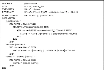
MACHINE phonebook
SETS NUMB ; NAME_SET VARIABLES NAME , pbook
INVARIANT NAME eP(NAME_SET) ¶ pbook e NAME ƒ NUMB INITIALISATION NAME := 0 || pbook := 0
OPERATIONS
add (numb) =
PRE numb e NUMB THEN
SELECT numb ‰ ran(pbook) THEN
ANY name WHERE name e NAME_SET-NAME THEN
NAME := NAME U {name} || pbook(name):=numb END
END
END;
remove (name) =
PRE name e NAME THEN
NAME := NAME - {name} || pbook := {name} y pbook END;
numb a lookup (name) = PRE name e NAME THEN
numb := pbook(name) END
[image:3.595.96.500.71.343.2]END
Figure 1 – B specification of a telephone book
In the B notation, invariants are used to define the type of each variable. In this case, the variable, NAME, represents the set of names that are currently in the phone book. NAME is declared as belonging to the powerset2 of NAME_SET, the set of all possible names. The variable, pbook, represents the phone book mapping names to numbers. pbook is declared to be an injective3 function ensuring that numbers in the phonebook are unique. Initially, pbook is empty. In the machine's operations, preconditions define the type of any arguments. Additional ‘guards’ may be specified on the arguments or on state variables. For example, in the add operation, numb must not belong to the range of pbook. Also in the add operation an unused name is selected non-deterministically using an ANY selector and its corresponding phonebook number is set, pbook(name):=numb, via indexed assignment. Operation behaviour is defined via 'substitutions' that show how the final state of machine variables depends on their initial state and the arguments. (Any state variables not defined in an operation body are not altered by it). Operations may return values in which case, the identifier(s) representing the return value(s) are defined at the beginning of the operation signature (e.g. numb in operation lookup). Other symbols used in the example are: set union, U, and domain subtraction4
, y.
Semi-formal notations are notations that provide a set of symbols to represent specific roles in the description of a system, but have a loosely defined semantics. The use of a syntactically consistent notation generally brings a more formal feel to descriptions of systems than an English language description would. This can be misleading as the lack of a precise semantics leaves the description open to different interpretations. The Unified Modelling Language [Rumbaugh, Jacobson & Booch, 1998] is a notation for use in modelling object-oriented designs that is popular in industry. The UML has been criticised for lacking a formal
2 the powerset, P(S) of a set, S, is the set of all subsets of S.
3 an injective function is one in which each element of the range is mapped to by at most one element of the domain
semantics and hence being ambiguous. Allowing different users to apply their own semantic interpretations may have been a factor in its growth and helped in its development by allowing extensive experimentation. Now that UML is established, work is underway to provide a stronger semantic underpinning for its next version, UML2.0. This will allow rigorous verification and validation of UML models. A key feature of UML is its extensibility mechanisms, which allow users to develop their own semantic profiles for particular modelling domains. Perhaps the main driving force behind the adoption and development of the UML has been its ability to handle complexity [Booch, 2002] and facilitate reuse. (In part due to its object-oriented basis but also due to its modelling organisational facilities). Encapsulation, abstraction, inheritance, polymorphism and dynamic binding are key factors in this approach but introduce assurance and verification difficulties such as demonstrating traceability of requirements and verifying valid inheritance properties. This is especially important in safety critical application and has led to the formation of the OOTiA (Object-Oriented Technology in Aviation) working group5 to address safety and certification issues when object-oriented software is used in airborne applications. Integration of formal techniques can solve some of these concerns by providing the necessary rigorous verification [Crocker, 2003]. Although most use of UML so far seems to have been as a low-level design tool (the trend has been for model-code integration tools) the OMG’s drive for model driven development indicates that future trends will be for it to be used at higher levels supported by transformations to the platform dependent level. For this to be workable platform independent models will need to be precise and integration with formal specification will contribute greatly.
1.1 Integrating Formal and Semi-Formal Notations
An integration of semi formal and formal notations may address the lack of formal semantics of semi formal notations while making formal specification more approachable. In a survey of industry, Craigen, Gerhart and Ralston [1995] found that better integration of formal methods with existing software assurance techniques and design processes was commonly seen as a major goal. They concluded, “Successful integration is important to the long term success of formal methods”. Fraser, Kumar and Vaishnavi [1994] describe a framework for classifying formal specification processes and choose the degree of transitional semiformal stages as being the most significant distinguishing characteristic. Jackson [2000] has developed a formal notation, Alloy and associated tool the Alloy Analyzer. The Alloy notation has a partial graphical equivalent notation in which state can be expressed. This can then be converted into the textual version of the notation where operations can be added and analyses performed. Without tools to investigate the implications of different structures however, the graphical format is limited to illustration of structure. The work of several research groups that have developed integrations between UML and B are described later. The precise UML group6 is a collaborative effort to precisely define UML semantics via formalisation. The UML already has its own formal constraint notation, OCL [Warmer and Klepp, 2003]. Despite its aim to be more approachable to practitioners by avoiding mathematical symbols, it has not been very popular with practitioners. This may be due to the concentration on UML as a visual code notation (when constraints aren’t useful). OCL has been criticised by some formal methods users for being cumbersome and awkward to use compared to traditional set based modelling notations [Vaziri and Jackson, 1999]. Our main reasons for not using OCL are that it is designed as an annotation notation whereas we require a full textual specification of the model elements for tool manipulation. Also, tool support for B is more mature than for OCL although this is improving [Toval et.al. 2003].
5http://shemesh.larc.nasa.gov/foot/
1.2 Difficulties translating from UML to B
At first glance it may seem that B has many features similar to UML, such as encapsulation of operations with associated state variables. However, one soon finds that a simple translation from classes to machines is problematic and other mappings are needed. This section identifies features of the B language that make it difficult to map object-oriented models to B. These features are, in general, due to the main purpose of B, which is to facilitate modular proof of large systems. The main motivation for translating UML into B is to enable design refinements to be formally proven. Therefore, for a translation to be useful it is important that the B is reasonably natural and does not complicate the proof process.
B is not object-oriented. A fundamental feature of object-orientated methods is the ability to model classes of objects via abstract data types. B has an encapsulation mechanism (machines) that allows variables to be grouped with the operations that act upon them. It is also possible, via machine renaming, to instantiate several instances of a machine. However, there is no mechanism to use the behaviour defined in this way to specify the behaviour of an indeterminate or variable set of instances. For example, Z [Spivey, 1988] has ‘promotion’ which enables schemas to be used to define a behaviour that is then promoted and bound to a set of instances at a higher level. This limitation is overcome by explicitly modelling the set of instances within the B and modelling each class feature with a function whose domain is the set of instances as will be described later.
Restrictions on B component and variable access. B contains restrictions on the way that operations can be called between and within machines. These restrictions are necessary in order to achieve composition of proof. The restrictions are as follows:
• A machine cannot have more than one other machine that makes calls to its operations. This means that, if a class-machine mapping is used, only one other class can access a class.
• There must not be any loops within the calling structure of a set of machines. This means that, if a class-machine mapping is used, only hierarchies of navigable associations can be translated and bi-navigable associations cannot be used.
• Operations cannot call other operations within the same machine. This can be avoided by repeating the substitutions of the ‘called’ operation within the ‘calling’ operation in place of the call. The disadvantages of repeating blocks of substitutions can be avoided by using B definitions (a text substitution, macro facility).
• Simultaneous calls to several operations of another machine are not allowed. This means that, if a one to one mapping between class methods and machine operations is used, class methods that simultaneously modify multiple instances of another class cannot be translated to valid B. This can be overcome by constructing a single operation of the associated class that alters the attribute values for multiple instances in a single substitution.
constraints and action specifications and proof and refinement are achieved via translation to B. Thus the limitations mentioned above are overcome.
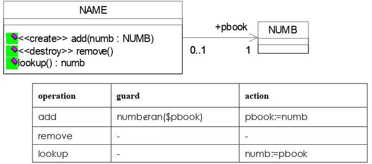
1.3 UML-B
This paper introduces a profile of the UML called UML-B [Snook, Oliver and Butler, 2004], illustrates its application through some small case studies and outlines how formal refinement may be applied to UML-B models. UML-B is precise and semantically well defined via equivalence to B. UML-B includes a condition and action language, µB, derived from B. A translator tool, U2B [Snook and Butler, 2004], is available so that B verification and validation tools can be used. To give a flavour of UML-B, consider the specification of the telephone book in Figure 2. The classes, NAME and NUMB represent people and telephone numbers respectively. The association role, pbook, represents the link from each name to its corresponding telephone number. Multiplicities on this association ensure that each name has exactly one number and each number is associated with, at most, one name. The table shows
µB conditions and actions for some of the operations. The add operation of class NAME has the stereotype <<create>> which means that it adds a new name to the class. It takes a parameter numb, which must be an instance of the class, NUMB, but not already used in a link of the association pbook (see µB operation guard), and uses this as the pbook link for the new instance (see µB operation action). This specification is equivalent to the B version introduced in Figure 1.
NUMB NAME
<<create>> add(numb : NUMB) <<destroy>> remove()
lookup() : numb
1 0..1
+pbook 1 0..1
operation guard action
add numb‰ran($pbook) pbook:=numb
remove - -
[image:6.595.101.467.345.507.2]lookup - numb:=pbook
Figure 2 – UML model of a telephone book
2 Motivation
2.1 Barriers to formal specification
Our main goal is to overcome barriers to enable formal methods to be used in industry. Through previous research [Snook and Harrison, 2001, 2004] and collaborative projects MATISSE7 and PUSSEE8 we have found that, given suitable training, software practitioners have little problem with understanding and using the kinds of mathematical notations that underpin current formal specification languages. We found that the main difficulty is in abstracting. This manifests itself in two forms, layering models into levels of abstraction and choice of coherent and useful abstractions within the levels.
7 Methodologies and Technologies for Industrial Strength Systems Engineering. IST-1999-11435 http://www.matisse.qinetiq.com/
Firstly, designers invariably launch straight in at a detailed level. They are primarily focused on production and hence model their ideas for building a device. They then enhance the model adding more and more detail in order to make it complete before generating code. The problem with this approach is that the model is incomplete until a very late stage. Since one of the main advantages to modelling is to verify and validate models at earlier stages (rather than the traditional approach of waiting until the code is available to test) most of the motivation for using formal models is lost. The solution to this problem may lie partly in training but also, modelling notations and processes could be improved. For example, we found that UML 1.4 lacks facilities for modelling in abstract-refinement layers (although UML 2.0’s components and hierarchical classes may address this to some extent). If designers are not used to abstract modelling with informal notations they are unlikely to be able to do so with formal notations. The second problem is choosing a useful and coherent set of abstractions to provide modelling entities. In order to investigate these difficulties in more detail we used a framework for assessing notations and interfaces called cognitive dimensions [Green, 1989]. Cognitive Dimensions provide a broad-brush qualitative tool for reasoning about the relative merits of information systems with respect to particular types of tasks. The cognitive dimensions framework consists of 14 terms that describe generalised facilities of information systems, notations or artefacts. Here we summarise the main insights we gained with respect to writing specifications in a formal notation. A fuller consideration is included in [Snook, 2001]. The main problems in writing a formal specification are the need to commit to abstractions at an early stage and the difficulty of subsequently altering these abstractions. Abstractions are needed to achieve a closeness of mapping of concepts in the model with those in the problem. Progressive evaluation would help ensure that the chosen abstractions are good ones before too much reliance is placed on them (premature commitment). However, formal verification is difficult even though it is provided via refinement. Improved animators and model checkers would address this. This is compounded by the difficulty of visualising abstractions in a mathematical notation. Considering that program design suffers from similar problems leads us to the hypothesis that the solutions adopted for program design would benefit formal specification in a similar way. A graphical design tool used to represent formal models would provide better visibility of abstractions and how they interact to compose the whole. This would be of value when assessing abstractions thereby alleviating premature commitment. The tool would also decrease viscosity (the effort of changing abstractions) since the diagrammatic symbols represent significant mathematical infrastructure and are therefore much quicker to re-arrange.
2.2 Influence of industrial projects on the development of
UML-B
3 The UML-B profile
The UML-B is a profile of the UML that defines a subset and specialisation of UML that has a mapping to, and is therefore suitable for translation into B language.
• A subset of the UML - including packages, class diagrams and state charts
• Specialisations of these features via stereotypes and tagged values,
• Structuring mechanisms (systems, components and modules) based on specialisations of UML packages
• UML-B clauses – a set of textual tagged values to define extra modelling features for UML entities,
• µB – an integrated action and constraint language based on B,
• Well-formedness rules
The UML-B profile uses stereotypes to specialise the meaning of UML entities, thus enriching the standard UML notation and increasing its correspondence with B concepts. The UML-B profile defines tagged values (UML-B clauses) that may be used to attach details, such as invariants and guards, that are not part of the standard UML. Many of these clauses correspond directly with those of B providing a ‘fallback’ mechanism for modelling directly in B when UML entities are not suitable. Other clauses, having no direct B equivalent, are provided for adding specific UML-B details to the modelling entities. UML-B provides a diagrammatic, formal modelling notation. It has a well defined, formal semantics as a direct result of its mapping to B. UML-B hides B’s infrastructure and packages mathematical constraints and action specifications into small sections each being presented in the context of its owning UML entity.
3.1
µ
B – as an action and constraint language
The UML initially concentrated on modelling the structural features of a software design. Notations were provided for expressing functional behaviour at a requirements level and state charts were available at lower levels, but the notations for expressing the behaviour of classes were incomplete. OCL can be used for expressing constraints on variable values within the model but a fully defined action notation is only now being introduced as part of UML 2.0. Many users were content to have incomplete models prior to the addition of code to implement behaviour. For our modelling however, we required a complete behavioural model. We therefore use a notation, µB (micro B) that borrows from B’s abstract machine notation (AMN). µB has the following differences from AMN:- An object-oriented style dot notation is used to show ownership of entities (attributes, operations) by classes. When attached to an entity belonging to a class, the context of an instance of the class is implicitly assumed. The symbol $ preceding any entity name means a class–wide reference to the entity (rather than the implied self.entity). The reserved word ‘self’ refers to the current contextual instance. (when µB is translated into B, self is translated into this<classname>, where
<classname> is the name of the class). µB can be used to construct expressions which can then be used in predicates or substitutions based on the context of the containing class. Expressions can be used to evaluate an arithmetic, set, relation or function value. Some examples of expressions are:-
S U T, the union of sets S and T,
R r r, the relation r restricted to only the set R as its domain (domain restriction)
owning instance for the current contextual instance may be omitted. For example, if ii is omitted in the above, var refers to the value of the variable var belonging to the current instance (self).
Predicates may use logic operators, such as conjunction, disjunction, implication and quantification, set predicates such as membership and subset, and number predicates such as greater and less than. For example the following predicate, attached to a class, C, tests an attribute, a, of the current instance to see whether it is less than the attribute, b, of all the linked instances in an association, s, to the class, D.
Ax • (x e D ¶ x e s ¶ a < x.b)
Since this constraint is specified in the context of a class, it is implicitly a constraint applied to all instances of the class and during translation will be elaborated to the following form. AthisC • (thisC e C ¶Ax • (x e D ¶ x e s(thisC) ¶ a(thisC) < b(x) ) )
Expressions may also be used to construct substitutions that are used to specify actions. Some examples of substitutions are,
att := FALSE, which sets the value of a boolean attribute of the current instance,
ANY yy WHERE P THEN att:=yy END selects any value of yy that satisfies the predicate P and sets the value of the attribute, att, belonging to the current instance, to this value.
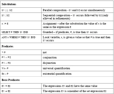
Some of the commonly used elements of µB are summarised in Table 1.
[image:9.595.98.497.352.682.2]Substitutions
S1 || S2 Parallel composition - S1 and S2 occur simultaneously
S1 ; S2 Sequential composition – S1 occurs followed by S2 (only allowed in refinements)
x := E Assignment – after the substitution the value of x is the
same as the expression E
SELECT P THEN S1 END Guarded – if predicate, P, is true then S1 occurs
ANY x WHERE P THEN S1 END Local variable, x, is given a value so that P is true and then
S1 occurs
Predicates
¬ P not
P1 ¶ P2 conjunction
P1 v P2 disjunction
Ax • P universal quantification
Ex •ÿP existential quantification
Basic Predicates
E1 = E2 The expressions E1 and E2 have the same value
E1 e E2 The expression E1 is a member of the set expression E2
Table 1 - Summary of commonly used µB elements
3.2 UML-B clauses
relevant entities. The UML-B profile defines the clauses that can be used via tagged values in this way. Any valid B clause (except OPERATIONS) has a corresponding meaning in UML-B although not all clauses are applicable with all modelling entities. For example, we use this method to specify invariants of a class. In addition to the usual B clauses, UML-B includes some clauses that extend UML to make alternative translation options available. The additional clauses are described later.
3.3 UML-B model architecture
Tag Name Applies to Description
module Package The package represents a B module.
machine Package The package represents a B machine component.
refinement Package The package represents a B refinement component.
implementation Package The package represents a B implementation component.
machine Class The class represents a B machine component.
refinement Class The class represents a B refinement component.
implementation Class The class represents a B implementation component
includes Dependency The supplier component is included in the client
imports Dependency The supplier component is imported in the client
sees Dependency The supplier component is seen in the client
refines Dependency The client component refines the supplier component. (For
[image:11.595.99.506.71.395.2]notation the UML realises arrow is used).
Table 2. UML-B stereotypes for model structuring and interrelationships
4 Class Diagrams
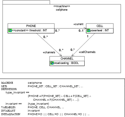
This section describes the translation of basic class diagram features from UML-B to B including the representation of class instances, class data features and relationships between classes, assuming a package-component based translation as described above. The complete class diagram content of a package is translated into a single B component. Each class is represented by B sets, constants, variables and operations and assembled into a single B component (i.e. machine or refinement, depending on the package stereotype). For example the model of a cellphone9 and its translation into B is shown in Figure 3.
CELL powerlevel : INT
CHANNEL broadcasting : BOOL
1
0..*
1
+cellChannels 0..*
PHONE
<<constant>> threshold : INT 0..*0..* 0..1 +current
0..1
+channels 0..*
0..* 0..*
0..* cellphone <<machine>>
MACHINE cellphone
SETS PHONE_SET ; CELL_SET ; CHANNEL_SET ; ... DEFINITIONS
type_invariant ==
(PHONE eP(PHONE_SET) ¶ CELL eP(CELL_SET) 
CHANNEL eP(CHANNEL_SET) ¶ ...); invariant == (type_invariant)
VARIABLES PHONE, CELL, CHANNEL, ... INVARIANT invariant
[image:12.595.100.500.82.455.2]INITIALISATION PHONE:=0 || CELL:=0 || CHANNEL:=0 || ...
Figure 3 Cellphone - example of UML-B model and its translation in B.
The current set of instances of each of the three classes is represented by the variables PHONE,
CELL and CHANNEL. These variables are defined in the type invariant as subsets of deferred sets (PHONE_SET, etc) that represent the set of all possible instances for each class. The current instances sets are used as instance identities when referring to and manipulating the features (such as attributes) owned by a particular instance. Initially, no instances exist and hence the current instances sets are empty. (Note that we use B’s macro facility, definitions, to structure the invariant. This is useful so that we can refer to parts of the invariant in predicates as well as for ensuring that the invariant is constructed in a valid order).
4.1 Attributes
In object-oriented notations, a class represents a set of instances and class features, such as attributes, are implicitly replicated for each instance of the class. Since B is not object-oriented, this fundamental characteristic of object-oriented systems must be explicitly modelled. Hence, attributes are translated into variables whose type is a function from the instances set to the attribute type. The value of an attribute belonging to a particular instance can then be obtained by function application. For example, if x is an attribute of type T in class
C, x is represented in the B model by a function mapping C to T and the value for an instance,
For example, the attributes of the cellphone example (Figure 3) are translated into B as follows.
MACHINE cellphone
...
CONSTANTS threshold
PROPERTIES threshold e PHONE_SET f INT DEFINITIONS
type_invariant == (... 
powerlevel e CELL f INT 
broadcasting e CHANNEL f BOOL ¶ ...); invariant == (type_invariant)
VARIABLES ..., powerlevel, broadcasting INVARIANT invariant
INITIALISATION ... || powerlevel := 0 || broadcasting := 0 ||
The attributes, powerlevel and broadcasting are represented by variables of type function, and are initially empty as there are no instances in their domains. The attribute threshold is stereotyped as a constant (a stereotype defined in the UML-B profile). It is translated into a constant function from the possible instances set to its type. The values of constants are therefore pre-ordained for all future instances of the class but may be different for each instance.
4.2 Associations
Associations are translated to functions in a similar manner to attributes except that the range of the function is based on the instances of the class at the supplier end of the association. Only associations that are navigable in one direction are used in UML-B. In UML, multiplicity ranges constrain associations. The multiplicities are equivalent to the usual mathematical categorisations of functions: partial, total, injective, surjective and their combinations. Note that the multiplicity at the target end of the association (class B) specifies the number of instances of B that instances of the source end (class A) can map to and vice versa. The multiplicity of an association determines its modelling as shown in Table 3. We use functions to subsets of the target class instances (e.g. P(B)) to model multiplicities with multiple targets. When the target multiplicity is at least one, P1 is used to ensure the subsets
Association Representations in B for Different Multiplicities
Ai and Bi are the current instances sets of class A and B respectively and f is a function representing the association (i.e. the role name of the association with respect to the source class, A).
disjoint(f) is defined in B as:
Aa1,a2•( a1 e dom(f) ¶ a2 e dom(f) ¶ a1Îa2 fi f(a1) I f(a2) =0 )
UML association
multiplicity Informal description of B representation B invariant
0..* Æ 0..1 partial function to Bi Ai ß Bi
0..* Æ 1..1 total function to Bi Ai f Bi
0..* Æ 0..* total function to subsets of Bi Ai fP(Bi)
0..* Æ 1..* total function to non-empty subsets of Bi Ai fP1(Bi)
0..1 Æ 0..1 partial injection to Bi Ai © Bi
0..1 Æ 1..1 total injection to Bi Ai ƒ Bi
0..1 Æ 0..* total function to subsets of Bi which don’t intersect Ai fP(Bi) 
disjoint(f)
0..1 Æ 1..* total function to non-empty subsets of Bi which don’t intersect Ai fP1(Bi) 
disjoint(f)
1..* Æ 0..1 partial surjection to Bi Ai ˚ Bi
1..* Æ 1..1 total surjection to Bi Ai ∆ Bi
1..* Æ 0..* total function to subsets of Bi which cover Bi Ai fP(Bi) 
union(ran(f))= Bi
1..* Æ 1..* total function to non-empty subsets of Bi which cover Bi Ai fP1(Bi) 
union(ran(f))= Bi
1..1 Æ 0..1 partial bijection to Bi Ai ˙ Bi
1..1 Æ 1..1 total bijection to Bi Ai ¬ Bi
1..1 Æ 0..* total function to subsets of Bi which cover Bi without intersecting
Ai fP(Bi) 
union(ran(f))= Bi 
disjoint(f)
1..1 Æ 1..* total function to non-empty subsets of Bi which cover Bi without intersecting
Ai fP1(Bi) 
union(ran(f))= Bi 
[image:14.595.87.513.77.587.2]disjoint(f)
Table 3 - How associations are represented in B for each multiplicity constraint
MACHINE cellphone ...
DEFINITIONS
disjoint(ff)== Aa1,a2 • ( a1e dom(ff) ¶ a2 e dom(ff) ¶ a1Îa2 fi ff(a1) I ff(a2)=0 ); type_invariant == (... 
current e PHONE ß CELL 
dspChannels e PHONE fP(CHANNEL) 
cellChannels e CELL fP(CHANNEL) ¶ ...);
CELL_invariant == (disjoint(cellChannels) ¶ union(ran(cellChannels)) =CHANNEL); invariant == (type_invariant ¶ CELL_invariant)
VARIABLES ..., current, dspChannels, cellChannels
INVARIANT invariant
INITIALISATION ... ||current := 0 || dspChannels := 0 || cellChannels := 0
The association, current, links a phone (but not all phones) with a single cell and is therefore a partial function. The other associations both link to zero or more channels and hence a total function to subsets of CHANNEL is used. For cellChannels, all channels are linked from exactly one cell and hence additional invariants are needed to ensure the sets of channels in the range are disjoint and cover all channels.
As for attributes, the stereotype, <<constant>> may be attached to an association. If the stereotype <<constant>> is attached to a class, it is equivalent to attaching it to all the attributes and associations of the class. A stereotype <<static>> may be attached to an attribute or association. This means that the attribute or association belongs to the class rather than a specific instance of the class and the instance mapping is suppressed giving a simple variable instead.
4.3 Translation of
µ
B
Constraints and actions expressed in µB throughout the model must be translated to reflect the translation of state modelling features from object-oriented constructs into the set based constructs available in B. We refer to this translation as T, where T(u) is the translation of the
µB expression u into B.
If a µB expression contains a reference to a class feature, a, belonging to a specified instance,
x, this would be written x.a in µB. As described in the previous section, the relationship between instances and the values of their features are represented in the corresponding B model by functions. Hence x.a is translated into the function application, a(x). If a is an association with a multiplicity greater than one at the target (supplier) end, then x is associated with a set of values. However, since the association is translated to a function from client instances to subsets of supplier instances, the translation to function application is still valid. The features of an instance of an associated class may also be referenced using the dot notation transitively through a sequence of association links. For example if an instance, x of the current class is linked with an instance of another class via an association, a and that class has a feature, b, then the value of b for the instance associated with x can be referenced as
is added as a parameter of the operation and the reference is translated to a(this<class_name>). When the reference is not associated with an operation, for example in an invariant attached to the class, the reference is implicitly generic for all instances of the class. In this case the same translation, a(this<class_name>), of a reference, a, is used and the complete expression is enclosed within a universal quantification for all instances of the class. For example if the
µB expression, u contains such a reference to a feature of the class, C. AthisC • (thisC e C fi T(u))
4.4 Behaviour
Behaviour is embodied in the specification of class operations and invariants using µB. This is illustrated in the examples below.
4.4.1 Invariant
Invariants are specified using µB in UML-B INVARIANT clauses, which may be attached to various modelling entities. Invariants are generally of two kinds, instance invariants (describing properties that hold between the attributes and relationships within a single instance) and class invariants (describing properties that hold between two or more instances of a class). For instance invariants, the explicit reference to self may be omitted. The translation will add universal quantification over all instances of the class automatically. For class invariants, the quantification over instances is an integral part of the property and must be given explicitly. The presence of explicit quantification is detected during translation. For example, if bx e NAT is an attribute of class B, then the following invariant could be attached to the class:
bx < 100 
Ab1,b2 • ((b1e B ¶ b2 e B ¶ b1Îb2)fi (b1.bxÎb2.bx)
The first part, bx<100, is an instance invariant because it applies to the attribute value for each and every instance of the class whereas the second part is a class invariant because it expresses a property that holds between the instances of the class. The invariant would be translated to:
AthisB • (thisB e B fi (bx(thisB) < 100)) 
Ab1,b2 • ((b1 e B ¶ b2 e B ¶ b1Îb2)fi (bx(b1)Îbx(b2)))
The translation has added a universal quantification,AthisB, over all instances of B in the first part of the invariant. It is not used in the second part where the invariant already explicitly references instances of class B.
The invariant is constructed as a set of definitions so that it, or parts of it, can be re-used in predicates, for example in the initialisation described later. The definitions also enable the type definitions to be collated so that they occur before any usage in a constraint and provide some traceability to the UML entity to which they are associated.
4.4.2 Operation specification
implicitly performed using the data that belongs to a particular instance of that class. Hence operations need to know which instance of the class they are to work on. Since B is not object–oriented, operations must be explicitly associated with a particular instance of the class by adding a parameter, thisCLASS, of type, CLASS, (where CLASS is the class name) to each operation. This is used as the instance parameter in each reference to an attribute or association of the class. The instance parameter is inserted prior to any explicit parameters belonging to the operation. Details of operation behaviour are specified textually in µB guards and actions attached to the operation. Hence, an operation, o, with parameters, p1,p2,...,pn of types T1,T2,...,Tn and return variables r1,r2,..,rn will result in the following format B operation.
r1,r2,..,rn a o(thisCLASS,p1, p2,...,pn) =
PRE thisCLASS e CLASS ¶ p1 e T1 ¶ p2 e T2 ¶...¶ pn e Tn THEN
SELECT <<guard>> THEN <<actions>> END
END
The guard is a µB predicate involving any of the variables in the package. The action is a µB substitution that updates the values of variables (attributes, associations etc.) of the class via substitutions as described in Table 1.
In Figure 4, PHONE has an operation startCall that attempts to start a call on the channel tt and returns a boolean representing its success. The call is successful if the channel is not already in use.
CHANNEL inUse : BOOL = FALSE PHONE
startCall(tt : CHANNEL) : success
+channels
0..* 0..*
[image:17.595.108.487.348.394.2]0..* 0..*
Figure 4- - example of operation specification
The operation, startCall, has a guard, ttechannels, to ensure that the parameter, tt, is a channel associated with the phone. Its action tests the inUse attribute of that channel:
IF tt.inUse = FALSE THEN tt.inUse := TRUE || success := TRUE
ELSE success := FALSE END
The operation is translated into the following B by U2B:
success a startCall (thisPHONE,tt) =
PRE thisPHONE e PHONE ¶ tt e CHANNEL THEN SELECT tt e channels(thisPHONE) THEN
IF inUse(tt) = FALSE THEN inUse(tt) := TRUE || success := TRUE
ELSE success := FALSE END END
END
4.4.3 Initialisation
Initial values of variable class features may be specified either as specific values or as predicates to constrain a non-deterministic initialisation. The initial value field of attributes may be used to specify their initialisation. For other entities, such as associations, the UML-B clause, INITIALISATION or INITIALISATION_PREDICATE, may be attached to the association or owning class. For example, an integer attribute x could be initialised to 0 by attaching the clause, INITIALISATION x:=0, or initialised to any value less than 10 by INITIALISATION_PREDICATE
x<10. For the latter case a convenient form of non-deterministic substitution is provided in B:
This is equivalent to a substitution that sets all of the variables in vars so that the predicate is true. It was found that this form of substitution was useful for U2B translation of initialisation constraints. If no initial values are specified the non-deterministic initialisation,
vars e(invariant) is provided by default. If any constraints on the initial values are provided in UML-B INITIALISATION_PREDICATE clauses, these are conjoined with the predicate:
vars e(invariant ¶ constraints)
4.4.4 Constructors and destructors
The <<create>> stereotype can be attached to an operation of a variable instance class to indicate that the operation is a constructor for the class. The operation will select an unused instance, initialise it as specified in the operation body (or on an attached state chart if it has a transition from the initial state with a matching event name) and return the instance. This allows parameterised constructors to be modelled. Any of the class’ variables (e.g. attributes, associations, state charts) may be initialised in the create operation, overriding any initialisation values defined elsewhere in the class (such as attribute initial values or initial transitions on state charts)
The <<destroy>> stereotype can be attached to an operation of a variable instance class to indicate that the operation is a destroyer for the class. The instance will be removed from the current instances set of the class and all maplets from that instance will be removed from the functions representing the variables of that class.
4.4.5 Subroutines
The use of the package-component translation (i.e. all classes from a class diagram in a single B machine or refinement) was found to be more usable than the original class-component translation but meant that there could be no method calling in the model. While this was found to be acceptable at an abstract level, as more detailed behaviour is added it is increasingly cumbersome to have to repeat common behaviour wherever it is needed. Also the design principles of encapsulation become more significant as the design progresses. To combat this limitation, the stereotype <<subroutine>> for class methods was introduced. Methods with this stereotype are translated into parameterised B definitions. Definitions are a literal, text substitution (macro) facility provided in B. Before a B component is type checked, each definition call is literally replaced by the definition body after substitution of the actual parameters. Since this is equivalent to repeating the behaviour, definitions can be instantiated wherever needed. (The alternative stereotype <<definition>> gives the same result for those that prefer a B style). The use of definitions in this way (which could become quite extensive if complex calling structures are modelled) has been found to be very effective. For example, in the cellphone model, a cell may need to initiate broadcasting on a particular one of its cellChannels. This could be achieved (Figure 5) by calling a subroutine, startBroadcast, which sets the attribute broadcasting to TRUE.
CHANNEL broadcasting : BOOL
<<subroutine>> startBroadcast() <<subroutine>> endBroadcast() CELL
powerlevel : INT
broadcastOn(ch : CHANNEL) +cellChannels
1 0..*
[image:18.595.107.489.602.665.2]1 0..*
Figure 5 – Example of use of subroutines
DEFINITIONS
startBroadcast (thisCHANNEL) == BEGIN broadcasting(thisCHANNEL):=TRUE END;
...
OPERATIONS
broadcastOn (thisCELL,ch) =
PRE thisCELL e CELL ¶ ch e CHANNEL THEN
SELECT ch e cellChannels(thisCELL) THEN startBroadcast(ch) END
END ;
4.5 Inheritance
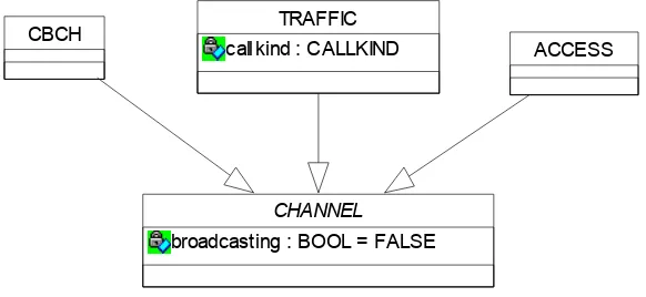
Inheritance represents subtyping of a class. The instances of the subclass are also instances of the superclass. Hence the subclass instances retain all the variables (attributes, associations and state variables) of the superclass but may add new variables that are only available to that subclass. Operation behaviour is retained by default but may be overridden (i.e. re-defined) in a subclass. For example, the cellphone model is further developed in Figure 6 using inheritance. A channel is one of three sub classes: an ACCESS channel, a TRAFFIC channel or a
CBCH channel. TRAFFIC defines a new attribute, callkind, which is only relevant to TRAFFIC
channels. It is assumed that instances belong to one and only one subclass and hence, sets of subclass instances are disjoint. If the superclass is abstract (i.e. doesn’t have instances other than those of its subclasses) then the subclass instances sets cover the set of super class instances. If B and C are subclasses of the abstract class A then their instances would be modelled as BzA ¶ CzA ¶ B I C=0¶ BUC=A.
CHANNEL
broadcasting : BOOL = FALSE
ACCESS
CBCH TRAFFIC
[image:19.595.102.393.379.513.2]callkind : CALLKIND
Figure 6 – example of inheritance
REFINEMENT cellphone1
REFINES cellphone
SETS CALLKIND={voice,data,other}
DEFINITIONS ...
type_invariant == (... 
CHANNEL eP(CHANNEL_SET) 
CBCH eP(CHANNEL) 
TRAFFIC eP(CHANNEL) 
ACCESS eP(CHANNEL) ¶ ... 
callkind e TRAFFIC f CALLKIND ) ; ... package_invariant == (
CBCH I TRAFFIC = 0
CBCH I ACCESS = 0
TRAFFIC I ACCESS = 0 ) ;
invariant == (type_invariant ¶ ... ¶ package_invariant)
VARIABLES ..., CHANNEL, CBCH, TRAFFIC, ACCESS, ... , callkind INVARIANT invariant
INITIALISATION ... || CHANNEL:=0 || CBCH:=0 || TRAFFIC:=0 || ACCESS:=0 ||
... || callkind := 0
5 Behavioural Specification by Statechart
For some behaviour models a statechart representation is useful. A statechart can be attached to a class to describe its behaviour via a set of one or more state diagrams. The behaviour expressed in the statechart is combined with any µB operation specification. Hence operation behaviour can be defined either in µB or in a statechart or in a combination of both. The name of the statechart model represents a state variable. The collection of states in the statechart is an enumerated set that provides the type of the state variable. The state variable is equivalent to an attribute of the class and may be referenced elsewhere in the class and by other classes. State transitions define which operation changes the value of the state variable from the source state to the target state. This means that an operation is only available when the state variable equals a state from which there is a transition associated with that operation. To associate a transition with an operation, the transition’s event name must be given the same name as the operation. Substates are currently not supported but will be considered in future work.
If there is a transition from the initial state on the state chart, the target state of this transition is the initialisation value for the state variable. If there is a named transition from the initial state on the state chart, the state variable will be initialised in a <<create>> operation of that name attached to the class. Similarly, named final transitions will result in <<destroy>>
operations which remove the instance from the instance set.
Additional guard conditions (defined in µB) can be attached to a transition to further constrain when it can take place. All transitions cause the implicit action of changing the state variable from the source state to the target state. Additional actions (also defined in µB) can be attached to transitions. The translator finds all transitions associated with an operation and compiles a guarded substitution of the following form:
SELECT statevar=sourcestate1 ¶ transition1_guards
THEN statevar:=targetstate1 || transition1_actions
WHEN statevar=sourcestate2 ¶ transition2_guards THEN statevar:=targetstate2 || transition2_actions etc
The guarded substitution generated from the state chart is composed with the operation precondition and body µB specification (if any). If Po is the µB predicate in the operation guard, So the substitution from the operation actions and Gs the guarded substitution composed from the statechart, then the translator will produce the following operation:
SELECT Po THEN Gs || So END
Hence the µB guard is on the overall operation and, if false, the operation will not be enabled. In guarded simultaneous substitutions, the substitution cannot occur unless each simultaneous branch is enabled. This means that the textual operation semantics, although not associated with any particular state transition, is only enabled when at least one of the state transitions is enabled. Actions should be specified on state transitions when the action is specific to that state transition. Where the action is the same for all that operation's state transitions, it may be specified in the operation body µB specification.
5.1 State dependant Invariants
For many of our case studies we found that we needed to specify invariants concerning the value of attributes and associations while an instance of a class was in a particular state of a state chart. In many cases the state chart model is an abstract view of behaviour that is gradually replaced by a collection of other variables. During these refinements the correspondence of states to the values of the other variables must be indicated by such invariants. The INVARIANT clause may be used on a statechart state to specify a predicate that should hold while an instances state variable is equal to that state. The hypothesis (statevar=state) is automatically added to form the sequent. (Quantification over all instances will also be added as before). Hence, for a class CC, with state model sv, if the clause, INVARIANT pp, is attached to a state ss, then the following invariant would be generated in the B model:-
AthisCC • (thisCC e CC fi ( sv(thisCC)=ss fi (T(pp)) ) )
where T(pp) is the translation of pp from µB into standard B.
An example of the use of invariants on states is shown in the example below.
5.2 Example of state chart behaviour specification
The example in Figure 7 illustrates how a statechart can be used to guard operations and define their actions and how common actions can be defined in the operation semantics window.
non_zero
inc / bx := bx+1
dec[ bx>1 ]
zero
newBB
inc / bx:=bx+10
[image:21.595.104.411.567.711.2]dec[ bx=1 ]
The statechart has two states, zero and non_zero. The implicit state variable, b_state (the name of the statechart) is treated like an attribute of type B_STATE = {zero,non_zero}. Invariants
bx=0 and bxÎ0 are attached to the states zero and non-zero respectively (not shown). When an instance is created its b_state is initialised to zero because there is an initial transition to the
zero state. This state diagram results in the following B.
MACHINE BB_CLASS
SETS BB_SET; B_STATE={zero, non_zero} DEFINITIONS
invariant == (
BB eP(BB_SET) ¶ b_state e BB f B_STATE ¶ bx e BB f NAT ¶ AthisBB • (thisBB e BB fi ((b_state(thisBB)=zero fi (bx(thisBB)=0)) )) ¶ AthisBB • (thisBB e BB fi ((b_state(thisBB)=non_zero fi (bx(thisBB)Î0)) ))
)
VARIABLES BB, b_state, bx INVARIANT invariant
INITIALISATION BB := 0 || b_state := 0 || bx := 0 OPERATIONS
Return a newBB =
ANY thisBB WHERE thisBB e BB_SET-BB THEN
BB := BB U {thisBB} || Return := thisBB || b_state(thisBB) := zero || bx(thisBB) := 0
END
END ; ...
Operation inc can occur in either state. Its action is different depending on the starting state and hence actions have been defined on transitions and are combined with the state change action. This results in the following B operation:
inc (thisBB) =
PRE thisBBeBB THEN
SELECT b_state(thisBB)=zero
THEN b_state(thisBB):=non_zero || bx(thisBB):=bx(thisBB)+10 WHEN b_state(thisBB)=non_zero
THEN bx(thisBB) := bx(thisBB)+1 END
END
Operation dec has two guarded alternatives when in state non_zero but does not occur while in state zero. Since the action, bx := bx-1 is the same for both transitions it has been defined in the operation’s µB actions specification rather than on a state transition. This results in:
dec (thisBB) =
PRE thisBBeBB THEN
SELECT b_state(thisBB)=non_zero ¶ bx(thisBB)=1 THEN b_state(thisBB):=zero
WHEN b_state(thisBB)=non_zero ¶ bx(thisBB)>1 THEN skip
END ||
bx(thisBB):=bx(thisBB)-1
END
5.3 State Chart Decision Points
alternative transitions. To mitigate this we introduced the use of decision pseudo-states and use them to structure sets of partially related transitions from a common source state as shown below. As shown in Figure 8 each decision point generates a SELECT substitution whose branches correspond to the outgoing transitions.
S1
S2
S3
S4 E1[ G1 ] / A1
[ G2 ] / A2
[ G3 ] / A3
[ G4 ] / A4
[ G5 ] / A5
E1 = SELECT state= S1 ¶ G1 THEN A1 ||
SELECT G2 THEN A2 || state := S2
WHEN G3 THEN A3 ||
SELECT G4 THEN A4 || state := S3
WHEN G5 THEN A5 || state := S4
END
[image:23.595.84.501.136.358.2]END END
Figure 8 – Ilustration of state chart decision points and translation into B
Decision pseudo states can also be used to merge several transitions (Figure 9) and events may be attached to the final transitions instead of the initial transition so that each merged tree is translated to different operations.
S5
S6
S7
S8 [ G5 ] / A5
[ G6 ] / A6 E8[ G8 ] / A8
E7[ G7 ] / A7 [ GG ] / AA
E8 = SELECT G8 THEN state:=S8 || A8 || SELECT GG THEN AA ||
SELECT state=S5 ¶ G5 THEN A5 WHEN state=S6 ¶ G6 THEN A6 END
END
END ;
E7 = SELECT G7 THEN state:=S7 || A7 || SELECT GG THEN AA ||
SELECT state=S5 ¶ G5 THEN A5 WHEN state=S6 ¶ G6 THEN A6 END
END END
[image:23.595.95.498.439.717.2]5.4 An alternative semantics for UML-B state charts
While working on the PUSSEE project, an example was discovered where the state chart translation was cumbersome and difficult to verify with the B tools. This led us to provide an optional alternative translation for state charts10. Each state gives rise to a set containing the instances currently in that state. A transition is enabled (subject to other guards) if the current instance is a member of the starting state. The transition removes the instance from the starting state and adds it to the target state. Initially the initial state contains all the instances of the class and the other states are empty. The state chart in Figure 10 produces two variables, S1 and S2, that are both of type P(C) (where C is the name of the class to which the state chart belongs). The invariant, S1 I S2={} ¶ S1 U S2 = C, ensures that the two sets are always disjoint. Initially, S1 contains all the instances, S1:=C || S2:={} . The transition event, e, is shown in Figure 10.
S1 e[ G ] / A S2
e (thisC) =
PRE thisC e C THEN
SELECT thisC e S1 ¶ G THEN
S1:= S1- {thisC} || S2 := S2 U {thisC} || A
[image:24.595.96.506.243.365.2]END END
Figure 10 – Illustration of ‘petri’ style state chart translation
Although the change of state is slightly longer (involving changing two variables instead of one), with this semantics it is easier to express guards that depend on the state of other instances. For example, S1={self} would enable the transition only when there are no other instances in S1. On the other hand, it can be more cumbersome to determine the current state of a given instance since this involves testing the membership of the instance against each state set. This alternative semantics should be used when you need to refer extensively to the set of instances in particular states in an invariant or guard.
6 Refinement
The B method is based on a hierarchical stepwise refinement and decomposition of a problem. After initial informal specification of requirements, an abstraction is made to capture the most essential properties of a system. For example, these could be the main safety properties in a safety critical system. This abstract specification is made more concrete and detailed in steps, which are of two types. The specification can be refined by changing the data structures used to represent state information or the operations that act upon these data structures. Alternatively, the specification can be decomposed into subsections via an implementation step that binds the previous refinement to one or more abstract machines representing the interfaces of the subsections. In a typical B project many levels of refinement and decomposition are used to fully specify the requirements. Once a stage is reached when all the requirements have been formally expressed, further refinement and decomposition steps add implementation decisions until a level of detail is reached where code can be generated. At each refinement or decomposition step, proof obligations are generated and must be discharged in order to prove that the outputs of the step are a valid refinement of the previous level. At each step when more detailed requirements are introduced or implementation steps are taken, it is proved that they respect all the previous levels. This
method ensures that the developed program obeys the properties expressed in all the levels of specification from which it is derived. Such proof is not always easily achieved. While the tool automatically discharges most proof obligations, typically some 20% require human interaction [ClearSy, 2000] and this interactive proof requires expertise and effort. The form and style of the formal B specification can greatly affect the ease of achieving these proof obligations. Hence ease of proof rather than any design paradigm becomes the primary criterion for developing specifications in B. This is why refinement and decomposition are the significant mechanisms in building a B specification. A mechanism for structuring a specification within a refinement level is provided (INCLUDES). This can be useful for segregating and encapsulating state data and its associated behaviour to aid understanding but contributes less to ease of proof.
6.1 Refinement in UML-B
Since our aim is to reflect the B method in our UML-B notation, we must cater for abstraction-refinement concepts in our UML-B models. Since we have purposely maintained a simple correspondence between UML entities and B components this is easily achieved. The stereotypes (‘machine’, ‘refinement’ and ‘implementation’) used to control the translation, identify the UML entities (packages) that are involved in the refinement structure. The entity refined by a refinement is indicated by a UML-B REFINES clause. There are several differences in the translation of refinements from those of machines. For example, the heading generated in the B component is different, a REFINES clause is added, and variables with the same names as those in the abstraction are assumed to have the same type. For example, in Figure 11, the cellphone model of Figure 3 is refined by a more detailed model in a new package cellphone1.
REFINES
cellphone1 <<refinement>> cellphone
[image:25.595.100.358.395.459.2]<<machine>>
Figure 11 – Using a package to indicate refinement
The refinement (Figure 12) uses inheritance to introduce three subclasses of the CHANNEL
class. The class is split into the subclasses CBCH, TRAFFIC and ACCESS, which will be represented by subsets of the CHANNEL instances set as discussed in the section on inheritance. This inheritance results in a corresponding refinement to the associations,
CBCH TRAFFIC callkind : CALLKIND
CELL powerlevel : INT
1 1 1 +cellCBChannel 1 1 0..* 1 +cellTRChannels 0..*
PHONE 0..*0..* +current 0..10..1
0..* 0..1 0..* +CBChannel 0..1 0..* 0..* 0..* +TRChannels 0..* ACCESS 1 4 1 +cellASChannels 4 0..* 0..4 0..* +ASChannels 0..4 CHANNEL
broadcasting : BOOL = FALSE
REFINEMENT cellphone1
REFINES cellphone
...
DEFINITIONS ...;
type_invariant == (...) ; PHONE_invariant == (...) ; CELL_invariant == (...) ; package_invariant == (...) ; invariant ==
(type_invariant ¶ PHONE_invariant ¶ CELL_invariant ¶ package_invariant); refinement_relation == (
AthisPHONE • (thisPHONEePHONE fi (dspChannels(thisPHONE)= {dspCBCH(thisPHONE)} U dspTrafficChannels(thisPHONE) U dspASChannels(thisPHONE) )) 
AthisCELL • (thisCELLeCELL fi ( cellChannels(thisCELL)= {cellCBCH(thisCELL)} U cellTrafficChannels(thisCELL) U
cellASChannels(thisCELL) )) )
VARIABLES ...
[image:26.595.98.499.80.581.2]INVARIANT invariant ¶ refinement_relation
Figure 12 – Class diagram and B model for refinement, cellphone1
In a B refinement, part of the invariant describes the relation between the variables of the refinement and those of the abstraction that they refine. This relationship is a special kind of invariant in addition to the internal constraints of the component itself. In UML-B, it is useful to distinguish the refinement relation from the rest of the invariant by providing a separate UML-B clause called REFINEMENT_RELATION. There are translation motivations for separating the refinement relation. The invariant may be used in an initialisation predicate whereas the refinement relation should not be used in this way. (This is because the variables of the abstraction are not visible anywhere other than in the B INVARIANT clause). For the
cellphone1 example, the refinement relation, shown in Table 4, specifies that, for each phone, the set of channels given by the abstract association channels, is formed from the sets of subclass instances given by the three new associations, CBChannels, TRChannels and
Class REFINEMENT_RELATION
PHONE channels = {CBChannel} U TRChannels U ASChannels
CELL cellChannels = {cellCBChannel} U cellTRChannels U cellASChannels
Table 4 – Refinement relation for cellphone1
7 Discussion and experience
In this paper we have described the translation of operation pre-conditions to B’s SELECT substitution. In fact this models the condition as a guard rather than a pre-condition. Intuitively, the difference is that an operation is ‘blocked’ or not available if its guard is false; whereas it is available, but not reliable, if its pre-condition is false. For our modelling of abstract action systems [Walden and Sere, 1998] where operations represent events that are observed to occur under certain conditions, we find guards more useful than pre-conditions. For modelling the subsequent development of programs, where operations are called by some external entity, UML-B provides an alternative modelling style where pre-conditions are translated into B pre-conditions and operations do not block.
UML-B was used successfully to formally develop the safety requirements for a real-time control system using an action systems approach [Snook, Tsiopolis, Walden, 2003]. This example concentrated on the refinement of statechart models using the transition decision points to refine transitions. The case study was successfully proven using the AtelierB prover throughout several levels of refinement as the system model was decomposed in subsystems. The case study also highlighted how sub states could be used as a natural form of refinement of state data.
Our experience has been that there is an encouraging level of interest in UML-B from industry. The interest is mainly from companies that are investigating formal methods but not using them. Their reaction is that they would probably not use B in its current (textual) form but they may consider using UML-B as it becomes more mature and usable. They view the UML basis of UML-B as providing a more understandable and visible route into using formal specifications. Several of our industrial contacts are keenly participating in ongoing research into the development of UML-B and U2B.
During the PUSSEE project, one of our industrial contacts, that had developed a B model with guidance from B experts, reported that, although they knew their B specifications were consistent (because they had proved it), they were unable to validate the specification. We transformed the B specification into UML-B and they said that they could now see what the model did. Since the B was changed slightly by re-modelling, we also translated back into B and proved the new model to make sure that it was no more difficult to verify.
There has been a mixed reaction from industry that already uses formal notations. Most see some benefit in the greater accessibility for novices that UML-B provides. Some thought that the UML-B version would be useful as documentation for customers but viewed B as the primary design notation. (Hence they were interested in a translation the other way). Others viewed UML-B as the primary design notation. Our view is that the initial modelling should be performed in UML-B, for the reasons discussed in motivation, but that it would be useful for small adjustments made during verification to be reflected back from B to UML-B.
it is easy to envisage the translation, which is actually quite difficult). The juxtaposition of classes and associations is clearly displayed so that the intention of the model constructs is more easily deduced. However, we can only go so far with the diagrams. They model the data structure (class diagrams) and the main changes of state made by operations (state charts) but textual specification is needed for details of constraints and actions. When actions and constraints are expressed textually in µB they are made more visible by hiding B infrastructure allowing their significance and context to be highlighted. A second reason why UML-B might be said to hide information is that UML structures a model into a hierarchical system of views. While this is often useful to aid clarity it is sometimes true that bits of information are difficult to locate or remember. For example it would be useful to be able to see invariants on diagrams. We agree that sometimes it is useful to be able to look at the B to get a more complete mathematical view. We do this less as we become more familiar with UML-B’s semantics but it is at least true that the B view has uses during learning stages and occasionally when the complete picture needs to be understood. We have taken to annotating class and state diagrams using notes to make textual constraints attached to diagram entities more visible. This makes the diagram more complete. It is not an ideal solution, however, because the notes are not part of the model and must be manually maintained to reflect the actual tagged values. An interim solution might be to write a tool to update these notes automatically but ideally we would like a UML drawing tool that allows tagged values to be displayed on the diagram.
Since the verification tools are currently B based (rather than UML-B based) it is important that the B view is available and is readable. Many people have commented on this fact and asked how the corrections can be traced back to the UML-B. In practice we have not found this to be a problem at all. If you are familiar with the UML-B model, the structure of the corresponding B is so similar that it is easy to locate the relevant components in the UML-B. This vindicates the aim of our approach, which is to maintain a simple mapping from UML components to B components in order to ensure that the B-based verification tools are practically usable. Several organisations, industrial and academic have indicated agreement with this philosophy compared with the approaches of others working on UML to B translation who may not have emphasised the importance of ease of proof sufficiently. The overall lesson is that proof is not easy (even with the current state of the art in semi-automatic provers) and if it is to be achieved, consideration must be given to provability in generating the models (whether writing B by hand or translating from UML-B).
Proof is an important issue and, in the future, we hope that the verification tools will be integrated better with UML-B. Ideally, the tools would work directly on the UML-B model and provide error and proof information in terms of this model. An intermediate stage that would be more easily achievable is for the tools to work with B but provide feedback into the UML-B to illustrate the errors. For example, the model checker might provide trace information as sequence diagrams. In the meantime we manually translate results back into corresponding changes in the UML-B model. We have not found this a problem with small to medium scale case studies. If traceability becomes an issue with large-scale projects, references could be embedded into the B using comments.