i
STUDY ON THE EFFECT OF DIFFERENT TIRE MODEL ON SPEED CHARACTERISTICS OF A VEHICLE MODEL
MOHD NASHRUL ASHRAF BIN MOHD NASRIN
ii
STUDY ON THE EFFECT OF DIFFERENT TIRE MODEL ON SPEED CHARACTERISTICS OF A VEHICLE MODEL
MOHD NASHRUL ASHRAF BIN MOHD NASRIN
This report is submitted
in fulfillment of the requirement for the degree of Bachelor of Mechanical Engineering (Automotive)
Faculty of Mechanical Engineering
UNIVERSITI TEKNIKAL MALAYSIA MELAKA
ii
DECLARATION
I declare that this project report entitled “Study On The Effect Of Different Tire Model On
Speed Characteristics Of A Vehicle Model” is the result of my own work except as cited in
the references
Signature : ...
Name : Mohd Nashrul Ahraf Bin Mohd Nasrin
iii
SUPERVISOR DECLARATION
I hereby declare that I have read this project report and in my opinion this report is
sufficient in terms of scope and quality for the award of the degree of Bachelor of
Mechanical Engineering (Automotive).
Signature : ………
Supervisor 1 : En. Faizul Akmar Bin Abdul Kadir
iv
DEDICATION
v ABSTRACT
vi
ABSTRAK
Laporan ini mengkaji berkenaan pemodelan dan simulasi terhadap sistem pergerakan membujur sesuatu kenderaan. Langkah-langkah untuk proses pemodelan dan perolehan persamaan matematik dibincangkan secara lebih mendalam dalam laporan ini. Seterusnya, model kenderaan dalam pergerakan membujur yang lengkap akan dibina dalam perisian Matlab Simulink R2013. Ia mengandungi model enjin, model dinamik kenderaan, model dinamik roda, nisbah kegelinciran secara membujur, dan juga model tayar. Untuk model tayar. dua model tayar akan dimodelkan untuk digabungkan kedalam model kenderaan dan seterusnya akan melalui ujian-ujian berdasarkan beberapa aspek seperti prestasi pecutan (Vx), pekali geseran diantara tayar depan kenderaan dan permukaan jalan (μ), nisbah gelenceran (S), dan daya membujur (Fx),bertujuan untuk
vii
ACKNOWLEDGEMENT
First of all, gratefulness of thanks to our Creator, ‘Allah’ for this blessing, which make this study become easier and can be finished on time.
I would like to express my gratitude and appreciation to all those who gave me the possibility to complete this report, especially to my final year project supervisor, En. Faizul Akmar Bin Abdul Kadir for his valuable guidance, support and encouragement throughout this project, especially in writing this report. I would like to appreciate the guidance given by other supervisor as well as the panels especially in my project presentation that has improved my presentation skills by their comment and tips.
I also would like to thank my classmates and friends that either directly or indirectly assists me in learning and using MATLAB software so that I can complete this study, and improve my own skills.
Last but not least, to my parents, En. Nasrin and Pn. Halimatun and also my siblings that always be there for me when I really need them, thank you for help me mentally to makes this final year report become a success.
viii
TABLE OF CONTENTS
CHAPTER TITLE PAGE
DECLARATION ii
SUPERVISOR DECLARATION iii
DEDICATION iv
ABSTRACT v
ACKNOWLEDGEMENT vii
TABLE OF CONTENTS viii
LIST OF FIGURES xi
LIST OF TABLES xii
LIST OF SYMBOLS xiv
1 INTRODUCTION 1
1.1 Background 1
1.2 Problem Statement 3
1.3 Objective 3
1.4 Scope Of Project 4
2 LITERATURE REVIEW 5
2.1 Introduction 5
2.2 Vehicle Longitudinal Model 5
2.3 Vehicle Dynamics 6
2.4 Vehicle Longitudinal Motion 8
2.5 Vehicle Transmission 9
2.6 Tire Model 10
2.6.1 Brush Model 11
ix
2.6.2.1 Pacejka- Magic Formula 12
2.6.2.2 Calspan Model 13
2.7 Software Approached: MATLAB Simulink 14
3 METHODOLOGY 15
3.1 Introduction 15
3.2 The Two-Wheel Traction Model 17 3.3 Vehicle System Block Diagram 18
3.4 Equations Of Motion 19
3.4.1 Vehicle Load Distribution 19
3.4.2 Drag Forces 20
3.4.3 Tractive Properties of Tire/road Interface 20 3.4.4 Wheel Dynamic equations 24
3.5 Powertrain Model 25
3.5.1 Engine Torque 25
3.5.2 Engine Dynamics 26
3.5.3 Gearbox Model 26
3.6 Parameter Selection 27
3.7 Simulation Model 28
3.7.1 Vehicle Body Dynamics Model 28
3.7.2 Tire Model 34
3.7.3 Wheel Dynamics Model 36
3.7.4 Powertrain Model 37
3.7.5 The complete vehicle longitudinal motion model (with Pacejka tire model)
40
3.76 The complete vehicle longitudinal motion model (with Calspan tire model)
43
3.8 Model Testing 44
4 RESULT AND DISCUSSION 45
4.1 Introduction 45
4.2 Validation of vehicle model 45
x
4.3.1 1st analysis: Acceleration performance, Vx 47 4.3.2 2nd analysis: Coefficient of friction, μ 49 4.3.3 3rd analysis: Slip ratio, S 50 4.3.4 4th analysis: Longitudinal Force, Fx 52
5 CONCLUSION AND RECOMMENDATION 54
5.1 Conclusion 54
5.2 Recommendation 55
REFERENCES 56
xi
LIST OF FIGURES
NO TITLE PAGE
1.1 Forces Acting On A Vehicle 1
1.2 Example of Block Diagram 2
2.1 Brush Model 11
2.2 Simulink layout 14
3.1 Research Flowchart 16
3.2 Schematic Of The Two-Wheel Traction Model 17
3.3 Vehicle System Block Diagram 18
3.4 Typical Engine Torque Data 25
3.5 Automatic Gearbox Shift Map 26
3.6 Steps for Vehicle body Dynamics Model 28
3.7 Equation A 29
3.8 Function block 30
3.9 Equation B 30
3.10 Equation D for front 31
3.11 Equation E for rear 31
3.12 Aerodynamic resistance force, Fa 32
3.13 Rolling Resistance forces, Fr 32
3.14 Equation F 32
3.15 Vehicle Body Dynamics Model 33
3.16 Subsystem of Vehicle Body Dynamics Model 34
3.17 Tire Model 34
3.18 Equation 3.8 35
3.19 Equation 3.7 35
3.20 Subsystem of Tire Model 35
xii
3.22 Subsystem of Wheel Dynamics Model 36
3.23 Subsystem of Powertrain Model 37
3.24 Powertrain model (Equation 3.27) 37
3.25 Equation 3.24 38
3.26 Equation 3.25 38
3.27 Equation 3.26 38
3.28 Gearbox Shift Map Model 39
3.29 The Complete Vehicle Longitudinal Motion Model with Pacejka
40
3.30 Tire Model Combined with Slip Ratio Model 41
3.31 Calspan Tire Model 42
3.32 The Complete Vehicle Longitudinal Motion Model with Calspan
43
4.1 Actual Acceleration Performance 46
4.2 Model Acceleration Performance For Dry tarmac (in MPH)
46
4.3 Acceleration Performance Comparison 48 4.4 Coefficient Friction Between Tire And Road Surface
Comparison
50
4.5 Slip Ratio Of Tire Comparison 52
xiii
LIST OF TABLES
NO TITLE PAGE
3.1 Road Conditions 21
3.2 Pacejka Model Parameters 21
3.3 Calspan Model Parameters 23
xiv
LIST OF SYMBOLS
m = Lumped mass, kg
ω = Rotation rate of wheels, rpm
R = Rolling radius, m
J = Polar moment of inertia, kg.m2
μ = Coefficient of friction between wheels and contact surface
L = Wheelbase length, m
θ = Road gradient, degree
ρ = Density of air, Kg/m3
A = Frontal area of the vehicle, m2
Fx = Longitudinal forces acting on a vehicle, N Fy = Lateral forces acting on a vehicle, N Fz = Vertical forces acting on a vehicle, N
V. = Forward velocity, km/h
Fa = Aerodynamic resistance forces, N
Fr = Rolling resistance forces, N Fd = Drag forces, N
λ = Slip ratio
𝜏𝑒 = Torque delivered by engine to each wheel, Nm
𝜏𝑟 = Reaction torque on each wheel, Nm
xv Cf = Viscous friction coefficient
Cd = Aerodynamic drag coefficient Cr = Rolling resistance coefficient
𝜂𝑔 = Current gear ratio
1 CHAPTER 1
INTRODUCTION
1.1 Background
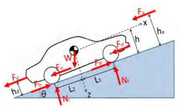
Every moving vehicle has its own characteristics. It includes weight of vehicle
acting to center of gravity, tractive forces, vertical and longitudinal forces, acceleration
[image:17.595.171.459.319.495.2]etc. These characteristics can be seen more clearly by using the Figure 1.1 below:
Figure 1.1: Forces Acting On a Vehicle
The simplified version of real system is called the mathematical model. To develop
vehicle longitudinal model due to Newton’s second law, the vehicle system block must
be created first. The system consist of vehicle body dynamics, front tire model traction,
front wheel dynamics, powertrain model ,brake system model, real wheel dynamics and
rear tire traction model. Throttle and brake settings are chosen as the main inputs, and
the outputs are vehicle velocity, and the front/rear wheel velocities. In order to design a
controller, a good representative model of the system is needed. A vehicle
2
described in this report. The mathematical model then will be put into equation in block
diagram in Matlab Simulink that can be shown in Figure 1.2:
Figure1.2: Example of Block Diagram
The model here retains the elements necessary for dynamics of the system although
it relatively simple. The model is intended to calculate the motion of a passenger
vehicle when driving in normal conditions, representing real vehicle behaviour in
public roads.
Tire important to vehicle control system because it generates the forces that
drive and maneuver the vehicle. The tire is a system with input and output quantities.
The tire is a main component of the wheel-road contact as it ensures three important
functions which are bearing the vertical load and absorbing road deformations,
producing longitudinal acceleration efforts and contributing to vehicle braking, and
producing the required transversal efforts that help the vehicle turning (Kiencke, 2005).
The motion of the wheel body with respect to the road covers the six input quantities
such as the side slip angle and the fore slip, while the tire with its deflections and
natural frequencies produces the six output quantities, such as the cornering force and
the normal load. Fundamental differential equations for a rolling and slipping body are
derived for serving the tire modeling process in later chapters. Finally, a discussion of
3
Modeling the efforts at the wheel-road contact has been widely regarded nowadays.
In this respect, several tire models have been developed with quite different properties,
such as Pacejka ‘magic’, Calspan, Dugoff, Kiencke, and Gim. These tire models will be
analyzed and compared further more in later stage of this study.
1.2 Problem Statement
Designing a new or modifying an existing vehicle is a complex, time-consuming
process that brings both technical and process challenges. There is an issue of how
using software like Matlab Simulink can make the modelling process become easier
rather than by test it to real vehicles. Besides that, it is well recognized that tires play an
essential role in all aspects of a vehicle behavior. Tires generate the forces that drive and
maneuver the vehicle. The knowledge of magnitude, direction and limit of the tire
forces are essential and valuable for vehicle control systems. However, the estimation of
these variables in all driving conditions and in real-time is a very challenging task.
There are few tire models that when it is implemented into computer code, it is not
compatible with low speed moving of vehicle, such as Pacejka. There a question arises
about how by changing the tire models affect the speed characteristics of the vehicle
model itself.
1.3 Objective
The objectives of this project are as follows:
1. To develop vehicle longitudinal model in MATLAB Simulink
2. To apply different tyre model to the vehicle ie: Pacejka vs Calspan
3. To compare the performance of each tyre model proposed by measuring the
4 1.4 Scope Of Project
The scopes of this project are:
1. All equation of speed characteristics that related to vehicle dynamics are
modelled by using MATLAB Simulink R2013 software.
2. The vehicle longitudinal models used to describe the dynamics in this report
are based on two-wheel traction model/half-car model.
3. The analyses of the simulation are measured in kilometre per hour (KPH)
5 CHAPTER 2
LITERATURE REVIEW
2.1. Introduction
This chapter describes a general overview of this research. Modeling and
simulation of vehicle dynamics has become a very important area in vehicle research in
recent years. There are numerous controls techniques studied such as linear and
adaptive control, genetic fuzzy control, and scheduling gain control PID. However, the
aspect of tire model still important to the vehicle dynamics performance.
2.2. Vehicle Longitudinal Model
The distribution of longitudinal forces has a large influence on vehicle handling
characteristics such as the driver/vehicle interaction, road holding and yaw stability, in
particular during combined traction/braking and cornering near the grip limit of the
tires. (Klomp, 2010). Ohstsuka and Vlacic in their study, proposed about a vehicle
longitudinal model targeted towards low velocity adaptive cruise control system, which
is presented through a review of conventional models. The vehicle model has two
inputs in term of engine input and the brake input. The models also described by the
composite of the power-train system model, the brake system model and the drive-train
model. The resulting response from the proposed model then is examined through
6 2.3.Vehicle Dynamics
Vehicle dynamics is the theory of how tire and aerodynamic forces acting on a
vehicle affect the vehicle motion, response, stability, and other characteristics. Vehicle
dynamics thereby provides the important aspects necessary to understand the
phenomena described above and which are important for a safe driver/vehicle/road
interaction. The main focus in the field of vehicle dynamics was on improving the
brakes and tires due to the demands of increased vehicle speed (Klomp, 2010).
Occasionally in presenting the dynamic model of a vehicle, the model of the tire
has been excluded for simplification, despite being understood as the main realistic
source to push the vehicle forward during acceleration (tractive effort) and to hold (or
reduce the velocity) the vehicle when applying the brake (braking effort), instead the
torque produced at the wheels through the power train is directly considered as a source
of pushing the vehicle forward and subsequently the brake torque to reduce the speed
of the vehicle. In reality, apart from the effect of the aerodynamic force and the
gravitational force (during travelling the vehicle up/down hill) on the longitudinal
performance of a vehicle, the forces developed between the tire and the road contact
interface have significant impact on the performance of the vehicle. The performance
of a vehicle such as motion of accelerating, braking, cornering and ride is a response to
forces imposed. The dominant forces acting on a vehicle to control performance are
developed by the tire against road. Therefore, it is necessary to develop an
understanding of the behaviour of tires, characterized by the forces and moments
generated over the various conditions of which the vehicle operate (Shakouri, 2010).
The study of vehicle dynamics can be accomplished by two method, which are
empirical method and analytical method. The empirical one is based on understanding
7
which way, and under what conditions. However, this method often leads to failure.
This is because without mechanic understanding of how changes in vehicle
design/properties affect performance, extrapolating past experience to new condition
may involve unknown factors which will produce result that defying the prevailing
rules of thumb. For this reason, the analytical method is more favourable by engineer.
This method firstly attempts to describe the mechanic of interest based on known law
of physics and then the analytical models will be established. These models can be
represented by algebraic or differential equations that relate forces or motions of
interest to control inputs and vehicles or tire properties. These equations then allow one
to evaluate the role of each vehicle property in the phenomenon of interest. By doing
the models, it provides a means to identify the important factors, the way they operate,
and under what conditions. It also provides a predictive capability as well so that the
changes necessary to reach performance goal can be identified (Gillespie, 1992).
Konrad Reif (2014) in his study about basic principles of vehicle dynamics, states
that a body only can be move or change course by the force action. There are many
forces that could act upon a vehicle when it is being driven. Tire aspect should plays an
important role as any change of speed or direction may involve forces acting on the
tires.
Meanwhile, Olson (2003) proposed about a formulation where the slip is taken to
be a dynamic state variable, replacing the absolute rotational rate of tire/wheel. Liu,
June (1995) in his study has already developed the equations of motion for quarter car
model in that way, but their study was more focusing on control algorithm based on
gain-scheduling, rather than dynamic behaviour generally. Therefore, a formulation
was created, that focusing more on general dynamic characteristics of the vehicle
8
and also slip values to be captured by a scalar function, in terms of brake/engine
torque, slip and friction/slip relationship. The dynamic model presented here are
capable of demonstrate the way of vehicle can undergo stable braking or acceleration,
depending on engine/brake torque, friction characteristics and the vehicle parameters.
2.4.Vehicle Longitudinal Motion
Vehicle longitudinal motion control objective is to ensuring passenger safety and
comfort. It is an important aspect in dynamic collaborative driving such as when
multiple vehicles should coordinate to share road efficiently while maintaining safety.
For this reason, several works have been sought to create something like an adaptive
cruise control that consists in maintaining a specified headway between vehicles.
Different control techniques used including linear and adaptive control, genetic fuzzy
control, and scheduling gain control involving .There is a need to create a longitudinal
control that are based on simple models neglecting important nonlinear aspects of the
vehicle such as rolling resistance, aerodynamics effects and road load. The model
should accounts for most vehicle nonlinear dynamics including tire-road interaction. A
suitable control model is developed for the vehicle longitudinal behaviour. The aspect
considered to meet the accuracy requirement here are not only the aerodynamic
phenomena, but also tire-road friction. Modelling the tire/road contact is a quite
complex issue involving multiple aspects relevant to tire characteristics (e.g. structure,
pressure) and to environmental factors (e.g. road load, temperature). Several tire
models being considered are Pacejka’s model, Gim’s model, Dugoff’s model, and