UNIVERSITI TEKNIKAL MALAYSIA MELAKA
INTELLIGENT IMAGE CAPTURING ALARM SYSTEM TO
PROTECT YOUR LOCKER USING RASPBERRY PI
This report submitted in accordance with requirement of the Universiti Teknikal Malaysia Melaka (UTeM) for the Bachelor Degree of Engineering Technology
(Bachelor of Electronic Engineering Technology) (Industrial Electronic) (Hons.)
by
SHATHIS KUMAR A/L SUBRAMANIAM B071310261
FACULTY OF ENGINEERING TECHNOLOGY 2016
DECLARATION
I hereby, declared this report entitled “Intelligent Image Capturing Alarm System To Protect Your Locker Using Raspberry Pi” is the results of my own research except as
cited in references.
Signature : ……….
Author’s Name : Shathis Kumar A/L Subramaniam
APPROVAL
This report is submitted to the Faculty of Engineering Technology of UTeM as a partial fulfillment of the requirements for the degree of
Bachelor of Electronic Engineering Technology (Industrial Electronic) with Honours. The member of the supervisory is as follow:
i
ABSTRAK
ii
ABSTRACT
iii
DEDICATION
Dedicated to my beloved parents,Subramaniam Salamah ,
iv
ACKNOWLEDGMENTS
First and foremost, I want to express my most noteworthy appreciation to my supervisor, En. Ir. Nik Azran Bin Abdul Hadi for the guidance, inspiration, enthusiasm and motivation given all through the advancement of this project. Without his support and interest, this project would not be successfully accomplished as presented here.
v
TABLE OF CONTENT
Abstrak i
Abstract ii
Dedication iii
Acknowledgement iv
Table of Content v
List of Tables vii
List of Figures ix
List Abbreviations, Symbols and Nomenclatures xi
CHAPTER 1: INTRODUCTION
1.0 Introduction 1
1.1 Project Background 1
1.2 Problem Statement 2
1.3 Objectives 4
1.4 Work Scope 4
1.5 Thesis Outline 4
CHAPTER 2: LITERATURE REVIEW 5
2.0 Introduction 5
2.1 Home Surveillance Security System 5
2.2 Related Research 6
2.2.1 Research on the Wireless Sensor Network for Motion Detection 6 2.2.2 Research on Wireless Sensor Node for Detection of Intruders 7 2.2.3 Research on Home Alert Security System using
ZigBee Technology 9
2.2.4 Research on Remote Home Security System using Wireless
Sensor Network and GSM Technology 10
2.3 Research on home surveillance security system in the market 12 2.3.1 Home alarm system 3524 using global system
vi
2.4 Conclusion 13
CHAPTER 3: METHODOLOGY 14
3.0 Introduction 14
3.1 Research Methodology 14
3.2 Design of the system 16
3.3 Hardware Development 17
3.3.1 Raspberry Pi 2 17
3.3.2 Passive Infrared Radiation (PIR) Sensor 19
3.3.3 Light Emitting Diode (LED) 22
3.3.4 Buzzer 23
3.3.5 Logitech C270 HD Webcam 23
3.4 Project Flowchart 25
3.5 Software Development 26
3.5.1 Configuration of Raspberry Pi 2 26
3.5.2 Configuration of USB WiFi Dongle 30
CHAPTER 4: RESULTS & DISCUSSION 32
4.0 Introduction 32
4.1 Intelligent Image Capturing Alarm System To Protect Locker
Using Raspberry Pi Hardware and Software Design 32
4.2 Analysis on WiFi Dongle bandwidth 36
4.3 Analysis of the effect by the internal walls to the wireless signal 38 4.4 Analysis on the wireless signal when testing in an open space 41 4.5 Analysis on the performace of the PIR sensor with distance 42
CHAPTER 5: CONCLUSION & FUTURE WORK 44
5.0 Introduction 44
5.1 Conclusion 44
vii
REFERENCE 46
viii
LIST OF TABLES
2.1 Literature review summary 12
3.1 Specification of the Raspberry Pi 2 Model B 1GB 19
3.2 PIR Sensor pin configurations 21
3.3 PIR sensor setting of the jumper. 22
3.4 Specification of the F53GD4SR-1 LED 23
3.5 Specifications of Logitech C270 HD Webcam 24
4.1 Bandwidth test for WiFi dongle 34
4.2 Time taken for a complete cycle with existence of the internal walls 37 4.3 Time taken for a complete cycle within an open space 39
ix
LIST OF FIGURES
2.1 Sensor node block diagram 6
2.2 End node block diagram 7
2.3 Sensor node setup 8
2.4 C328R (CMOS) camera 8
2.5 XBee Module (S2) 9
2.6 GSM home alarm system 3524 13
3.1 Planning of the development of the project 16
3.2 Design system block diagram 17
3.3 Top view of the Raspberry Pi 2 Model B board. 18 3.4 Bottom view of the Raspberry Pi 2 Model B board 18
3.5 Pyro-electric sensor 20
3.6 Working principle of the PIR sensor 20
3.7 Red F53GD4SR-1 LED 22
3.8 Buzzer 23
3.9 Logitech C270 HD Webcam 24
3.10 Raspian Operating System 27
3.11 Raspian.img file 27
3.12 Win32DiskImager 28
3.13 Putty Configuration 29
3.14 Successful connection of Raspberry Pi through SSH 30 3.15 Configuration of Wifi network to Raspberry Pi 31 4.1 Front view of the intelligent image capturing alarm system setup 33 4.2 Top view of the intelligent image capturing alarm system setup 33
4.3 Raspberry Pi interface via desktop monitor 34
4.4 Result of the system 35
4.5 Email notification 35
4.6 Email content 36
4.7 Bandwidth reading 37
x
4.10 Time taken for complete cycle during 10 tests (open space) 41
xi
LIST OF ABBREVIATIONS, SYMBOLS AND
NOMENCLATURE
A/D - Analog to Digital
AC - Alternating Current
App - Application
AVR - Aboriginal Voices Radio
CMOS - Complementary Metal-Oxide Semiconductor CSI - Camera Serial Interface
DC - Direct Current
DSI - Display Serial Interface
EEPROM - Electrically Erasable Programmable Read-Only Memory FAT32 - File Allocation Table
Fps - Frames per second
FWT - Fixed Wireless Terminal
GND - Ground
GPIO - General-purpose input/output
GSM - Global System for Mobile communications
HD - High Definition
HDMI - High-definition multimedia interface
I/O - Input Output
IC - Integrated Circuit
INT - Interrupt
Kb - Kilobytes
LCD - Liquid Crystal Display LED - Light Emitting Diode MCU - Microcontroller
MHZ - Mega Hertz
Nm - nanometer
OS - Operating system
xii
PC - Personal Computer
PIC - Peripheral Interface Controller PIR - Passive Infrared Radiation
RAM - Random Access Memory
RF - Radio Frequency
RM - Ringgit Malaysia
SD - Secure Digital
Sftp - Secure File Transfer Protocol SMS - Short Messaging Service SMTP - Simple Mail Transfer Protocol SRAM - Static Random-Access Memory
SSH - Secure SHell
SSL - Secure Sockets Layer
µA - MicroAmpere
uF - MicroFarad
USB - Universal Serial Bus UVC - USB video device class
1
CHAPTER 1
INTRODUCTION
1.0 Introduction
This section consists of the project background, problem statements, objectives, the work scope, and thesis outline.
1.1 Project Background
In present days, the system of home security turns into an indispensable issue with the expanding cases of home breaking or thievery cases. Moreover, the system of home surveillance is essential since the house owner wants to screen their home's circumstances by identifying any undesirable and illegal activity (Nguyen et al. 2013). Years ago, the traditional home surveillance systems have obtained much demand. As time passes, the technology of traditional home surveillance systems has evolved and offers many exciting benefits to the user. These improvements have conquered the weakness of traditional security systems such as power loss caused by the turning on and turning off the process (Hidayat & Firmanda 2015).
2
Additional to the rising recognition of a proficient home security system, the utilization of continuous alert service is essential for the users (May 2012). Therefore, this project is developed using an Raspberry Pi 2 based image capturing alarm system. The intruder is detected using passive infrared (PIR) sensor's infrared (IR) radiation. The changes in radiation field are checked by the sensor. At the point when an intrusion happens, the presence of an intruder will be detected by the developed system and an image of an intruder will be captured simultaneously. From there on, an email will be sent to the user with the captured image as an attachment. Meanwhile, an LED will be turned on simultaneously in this developed system. The LED will be a replacement for house lamp due to the high cost of the lamp. Not only that, this system will also trigger an alarm sound to alert the house owner or surround people using a buzzer. As a conclude, the system will assist the house owner to make a report to authorized party with the intruder’s image as an evidence.
In this era of technology, exploration towards a product that costs reasonable price and capable of solving ideas is increasing. A small embedded microcontroller with a flexible platform utilization of the hardware projects is known as the Raspberry Pi. The Raspberry Pi 2 crosses off both criteria (Qianqian Yang et al. 2015). Raspberry Pi is a card-sized minicomputer that can either operate on mains or battery power. It has Linux as its operating system.
1.2 Problem Statement
3
be automatically detected by the motion detector thus the image of the moving object will be captured using the camera module installed. As a result, the snapped picture will be sent to the user or the house owner via email as an attachment. In respect to that, the proposed project will manage to capture an image upon detecting intruder’s motion. Furthermore, a quick move to make a report to the authorized party with the intruder’s image as an evidence can be made.
Besides that, an increase in locker break-in cases can occur due to the owner and the authorized party’s late action or movement. Owner’s lack of awareness of the unwanted incidents may cause this incident to occur often. Therefore, the system is developed to produce an alarm sound to alert surround people. Not only that, a notification will be sent via email to notify the owner that an intrusion had occurred in the house.
This project introduces a new technique by using Linux system software development with a USB camera (UVC compatible) attached together to it (Weerachai et al. 2011). The locker security system proposes a proper system that is convenient for the user to access. Besides that, some theft happens over and over due to lack of evidence. Hereby, the proposed project will give us enough evidence on the thief and makes it easier to make a report to the authorized party.
1.3 Objectives
The objectives of the project are:
i. To reduce the locker break-in cases.
ii. To alert the owner on possible locker intrusion .
4
1.4 Work Scope
There are advancement and coordination of numerous hardware and software with a specific end goal to accomplish the project objectives. The proposed project mainly focuses on a locker security system that will capture an image once the intruder is detected, as the work scope. The python language is used to program the Raspberry Pi 2 which acts as a server in this project. Other than that, a camera module and PIR sensor also been programmed using Python language to perform its desired function since it is attached to the Raspberry Pi 2. The PIR sensor is utilized to recognize any movement of the human or intruder to be specific. Then, those movements will be captured by the camera module. Since notification via email is included, a configuration is made to the Raspberry Pi 2 to install the SMTP library. The software and hardware components developed are integrated together. Finally, the analysis and verification are conducted to the system performance.
1.5 Thesis Outline
In this thesis, there three sections, namely chapters 1, chapter 2, and chapter 3. The project background, problem statements, objectives, and also the work scope are explained in chapter 1.
Chapter 2 consists of a literature review. The past researches by senior undergraduates and different researchers on the available home and locker security system on the market as of now will be discussed here.
5
CHAPTER 2
LITERATURE REVIEW
2.0 Introduction
This part of the report focuses on the past studies on a couple of vital keys related to the proposed project. Additionally a study on different projects that have been conducted by different researchers on the advancement of locker security system and also the availability in the current market (Khera & Verma 2014). The purpose of this chapter is to get valuable information, a general knowledge, and skills to develop this project successfully.
2.1 Home Surveillance Security System
6
2.2 Related Research
The proposed project was produced subsequent to directing some looks into to various researches that have been conducted by senior undergraduates. By examining the elements and the system design of the existing projects, recognizing their weakness or disadvantages will help to reach the objectives.
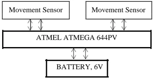
2.2.1 Research on the Wireless Sensor Network for Motion Detection
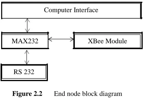
In this project, researcher has developed a system using Atmel ATMega 644PV as the fundamental microcontroller, a movement sensor, and the XBee radio frequency (RF) wireless module transceiver in order to build the sensor node. On the other hand, the XBee RF wireless module transceiver, MAX232 chip, and the RS232 serial port are used to make the end node (Hou et al. 2008). Figure 2.1 shows the block diagram of the sensor node and Figure 2.2 end node respectively.
Movement Sensor Movement Sensor
ATMEL ATMEGA 644PV
[image:21.595.205.457.472.602.2]BATTERY, 6V
7 Figure 2.2 End node block diagram
Researcher has used the XBee module as a junction to communication the sensor node and the end node to form a system topology. Based on the study, this system has a weakness where users will not have an evidence of the intruder since no image will be captured during an intrusion. Hence, the disadvantage to verify the intruder occurs in this system. As a result, the users will not get any sort of alert if they have left the house. This system can't guarantee whether the alarm truly showed the intruder.
2.2.2 Research on Wireless Sensor Node for Detection of Intruders
An improvement made referring to the Intelligent Home Security Surveillance System Based on ZigBee project (Hou et al. 2008). Based on the survey made, this project differs by adding a camera to the sensor node. The camera used is the C328R complementary metal-oxide semiconductor (CMOS). Otherwise, the sensor and end node's microcontroller and components are the same. Figure 2.3 shows how the sensor node is set up.
Computer Interface
MAX232 XBee Module
8 Figure 2.3 Sensor node setup.
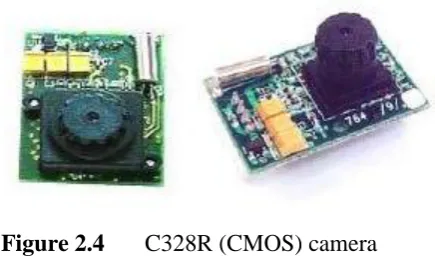
This project was improved by catching the picture of the intruder after a movement or motion is detected. After that, the picture will be sent to the base station. At the same time, a Short Message Service (SMS) will be generated and send to the remote user to alert on the intrusion. In order to use low-cost components, the C328R (CMOS) camera is used. Figure 2.4 shows the C328R CMOS camera used in this project.
Figure 2.4 C328R (CMOS) camera
[image:23.595.224.442.465.593.2]9 2.2.3 Research on Home Alert Security System using ZigBee
Technology
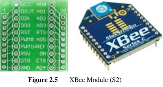
[image:24.595.188.473.289.441.2]The microcontroller (PIC 18F4550) and XBee module were used in this research. The XBee module consists of two parts called the 802.15.4 RF transceiver and ZigBee protocol stack. The microcontroller acts as the main controller or server in this development. The coding is programmed as per desired functions (Ahmad et al. 2011). Figure 2.3 shows the XBee module used in this research.
Figure 2.5 XBee Module (S2)