The Designers’ Workbench: Using
Ontologies and Constraints for
Configuration
David W. Fowler
University of AberdeenAberdeen, UK
Derek Sleeman
University of AberdeenAberdeen, UK
Gary Wills
University of SouthamptonSouthampton, UK
Terry Lyon
Rolls-Royce plcDerby, UK
David Knott
Rolls-Royce plcDerby, UK
Abstract
Typically, complex engineering artifacts are designed by teams who may not all be located in the same building or even city. Additionally, besides having to design a part of an artifact to be consistent with the specifica-tion, it must also be consistent with the company’s design standards.
The Designers’ Workbench supports designers by checking that their configurations satisfy both physical and organisational constraints. The system uses an ontology to describe the available elements in a config-uration task. Configconfig-urations are composed of features, which can be geometric or nongeometric, physical or abstract. Designers can select a class of feature (e.g. Bolt) from the ontology, and add an instance of that class (e.g. a particular bolt) to their configuration. Properties of the instance can express the parameters of the feature (e.g. the size of the bolt), and also describe connections to other features (e.g. what parts the bolt is used to hold together).
1
Background
Engineering designers typically have to find configurations of parts that im-plement a particular function. The engineering design process is constraint orientated, and requires the recognition, formulation and satisfaction of con-straints [LC02]. To assist designers, most organisations have built up a large number of design rules and standards, usually held as large volumes of text. Designers must try to ensure that their configurations satisfy these constraints, but it is often easy to overlook some. Novice designers often have a hard task in learning the constraints. On occasion, constraints may be modified or be-come obsolete. Also, new constraints may be added. In practice, it is often hard to find which constraints apply in a given situation. Additionally, in a collaborative environment, where many designers are working on subsections of a common component, it is common for changes made by one designer to affect the options available to another, but for this to go unnoticed until much later, causing expensive and time consuming redesigns.
It would clearly be useful to have some way of automating the design check-ing process, so that all applicable constraints are checked, without the designer having to manually initiate a search for the constraints. In our approach, we use an ontology to describe the available features and check the constraints au-tomatically. A constraint is specified by the conditions of applicability (which types of features it applies to), and the logical or mathematical expression that allows a constraint check to be performed.
2
Aims of Designers’ Workbench
The Designers’ Workbench deals mainly with problems that lie in the domain of configuration. Mittal and Frayman [MF89] define a configuration problem as selecting parts from an existing set of types, and connecting them using specified ports in such a way that certain constraints are satisfied and that particular functions can be performed by the resulting configuration. Brown [Bro98] discusses the adequacy of this definition. For our purposes, we will assume that ports can be described by properties of a feature, so that “normal” properties may have values that are simple data values to further describe the feature, whereas “port” properties have values that are other features. For an example, consider a class corresponding to bolts. An instance of this class will have properties that describe the size and shape of the bolt (real numbers or integers). There will also be properties that have values that are instances of other classes — for example, the has_materialproperty might have a value
steel, an instance of the Materialclass.
The current version of Designers’ Workbench allows designers to build a configuration and to check that all the appropriate constraints hold. We have used the term features, rather than parts or components, as we wish to em-phasise the fact that features can be abstract entities (such as temperatures, holes in other features, etc). Brown [Bro02] discusses a large number of differ-ent uses of the word “feature”, including functional features that we are also interested in. The designer can select a feature class from an ontology, and add an instance of it to the configuration. Each instance can have properties that are defined for the class that it belongs to. The properties that are defined for a particular type of feature can be of two kinds: datatype (integers, strings, reals etc), which are parameters of the feature; andobjecttype (other feature instances), which correspond to ports (connections to other features).
subconfigu-rations and checking that they satisfy the constraints. We have concentrated on checking that constraints are satisfied by a configuration produced by a human designer, rather than finding a solution. This has implications for tractability, in that solving a CSP is an NP-complete problem, whereas checking a solution can be done in polynomial time. The system has been implemented so that the human designer is free to use his or her engineering expertise to override constraints that are not deemed applicable to the current situation.
3
Related work
In this section we examine some approaches to the configuration problem, di-viding them according to whether they use constraints, or ontologies, or both. A general introduction to constraints can be found in [Kum92], and [CJB99] is an introduction to ontologies.
3.1
Constraint-based approaches
Bowen et al. [BOS90] describe a constraint based language, LEO, which enables parts of a design to be represented as a collection of variables, with domains that are not necessarily finite (for example, rational numbers or reals). The system allows constraints to be specified over these variables. Constraint checking, rather than solving, is preferred, because:
A constraint monitoring system . . . allows the designer to exercise his creativity, while relieving him of the drudgery of making many routine inferences and checks, thereby ensuring that the design choices he makes are consistent with good performance in all sig-nificant aspects of the product’s life cycle. Furthermore, constraint monitoring is less expensive, computationally, than constraint sat-isfaction. [BOS90]
A disadvantage of this approach, from the perspective of configuration, is that all variables must be declared at the outset. Also, the variables are not structured using classes. Variables corresponding to properties of features must be declared individually, whereas a structured system would associate properties with each feature class, and declare them automatically.
activity constraint might require that ifPackage=luxurythenSunroof must be active (and can take a value from its domain). In this way, non-luxury cars will not have sunroofs, whereas luxury cars will have a choice of two sun-roof types. “Normal” constraints (corresponding to CSP constraints) are only enforced on currently active variables. Algorithms are given to solve DCSPs. One disadvantage is that all variables must be specified in advance, making it awkward to represent problems whose solution may require several of the same type of component. For example, a configuration might require many bolts, but the exact number is not known before searching for a solution. Using a DCSP would require the declaration of a variable for every bolt that might possibly be needed.
Sabin and Freuder [SF96] definecomposite CSPs which allow configuration problems to be represented in a hierarchical fashion. In a composite CSP, some variables can be assigned a subproblem, rather than a simple value. In this way, components can be selected at a higher level, before being specified in terms of subassemblies. The example used in [SF96] is also car configuration. The car is divided hierarchically: for example, the power plant system is divided into an engine, exhaust system, electrical system, and so on. Each of these can be represented by a variable that has a domain that is a subproblem. For instance, the engine variable could have a domain that has two values, gasoline engine and diesel engine. During search, if one of these values is selected, a subproblem will need to be solved, containing variables such as pistons, rods, valves, etc. An advantage of the approach is that existing CSP search algorithms can be easily adapted to solve composite CSPs, by dynamically adding and retracting variables and constraints as required.
3.2
Ontology-based approaches
Lin et al. [LFB96] give an ontology for describing products. The main decompo-sition is intoparts, features,andparameters. Parts are defined as “a component of the artifact being designed”. Features are associated with parts, and can be either geometrical or functional (among others). Examples of geometrical fea-tures include holes, slots, channels, grooves, bosses, pads, etc. A functional feature describes the purpose of another feature or part. Parameters are prop-erties of features or parts, for example: weight, colour, material. Classes of parts and features are organised into an inheritance hierarchy. Instances of parts and features are connected with propertiescomponent of, feature of,and
subfeature of.
3.3
Combining constraints and ontologies
Stumptner et al. [SFH98] introduce an extension of CSP, Generative CSP,
which uses complex variables, each of which has an associated type. The type of a variable determines itsattributes (datatype properties), and itsports (ob-jecttype properties). The types are formed into a simple hierarchy. The con-straints here include activation concon-straints and compatibility concon-straints, in-troduced by Mittal and Falkenhainer [MF90]. In addition, resource constraints are used, being global constraints over all variables of a particular type.
Junker and Mailharro [JM03] describe a system, ILOG Configurator, that combines the power of description logic (to describe the parts used in a con-figuration), with constraint programming (to solve the configuration problem). The description logic uses classes that are either abstract or concrete. Con-crete classes are the leaf classes of the ontology, corresponding to actual parts. Abstract classes are the nonleaf classes. Properties are used to describe the instances of a class. Alternative methods can be used to specify the instances that can be part of a solution, ranging from an explicit list of instances, to an implicit list, where instances can be freely chosen from an infinite universe of instances. Generic constraints can be defined in a constraint language that allows numeric and symbolic constraints. To solve a configuration problem, a description logic representation of the class hierarchy and the constraints are converted into a constraint satisfaction problem.
Laburthe [Lab03] extends CSPs to cases where variables have domains that are taken from a hierarchy. This differs from the approach of the Designers’ Workbench (as well as that of [MW98] and [JM03] described above) in that we are concerned with constraints over values of properties of instances (ultimately datatype values). Laburthe’s approach aims to find the entities in a hierarchy that will satisfy the constraints. It is possible that this approach could be used to find suitable types for elements of a configuration.
4
An illustrative example
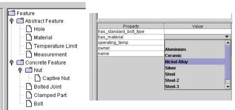
To illustrate the use of an ontology to describe a configuration, we will use the simple ontology whose class hierarchy is shown in Figure 1. We have used the concept offeatureas the root of the ontology. Features have then been divided intoconcrete features(those that have a material), andabstract features(holes, temperatures, etc).
Using this ontology, we can describe the simple arrangement of a bolted joint shown in Figure 2, subject to a particular environmental temperature. This is shown in Figure 3. Example constraints might include:
• Any concrete feature must have a material with a higher operating tem-perature than the prevailing environmental temtem-perature;
Feature
Concrete feature Abstract Feature
Bolt Nut Clamped part Material
Self-locking nut
[image:6.595.219.432.144.259.2]Environmental temperature
[image:6.595.238.409.311.454.2]Figure 1: The class hierarchy of a simple configuration ontology
Figure 2: A bolted joint [image from French, Vierck and Foster, “Engineering Drawing and Graphics Technology”, McGraw-Hill Inc.]
[image:6.595.187.464.522.651.2]although this can be dealt with, for example by defining aMeasurement
class of feature, with a real valued propertiesdimensionandtolerance.
The first constraint will apply to all features that have a has_material
property and an environmental_temperatureproperty defined. The second constraint is more complicated, and applies to all bolts, nuts, and clamped parts that are part of a bolted joint.
5
Functionality
An ontology written in DAML+OIL [DAM] describes available feature types. In the Designers’ Workbench, the designer can select a feature class from the ontology and create an instance of that class. The property values of the instance can then be filled in: datatype values by literals of the appropriate type, and object type values by selecting an instance from a list of all instances of the appropriate type.
Constraints are handled in a two stage process:
• Identify feature values that should be constrained;
• Formulate a tuple(s) of values for each set of feature values, and check that the constraint is satisfied by these values.
The constraint processing uses RDQL (RDF Query Language) [JEN] to find the constrained features. A disadvantage of using RDQL is that it cannot return arbitrary numbers of values from a query, making constraints on arbitrary numbers of features impossible to express. For example, the constraint on the sum of thicknesses of clamped parts cannot be expressed. To get around this, it is possible to have separate constraints for 1,2,3, ..., nparts, wherenis some arbitrary number, but this is clearly not ideal. Part of the future work will be to investigate other query languages or mechanisms to overcome this difficulty. After using RDQL to extract the values that are constrained, SICStus Pro-log [Swe03] is used for the process of checking that the constraints hold.
The RDQL query that locates features affected by the material temperature constraint is:
SELECT ?arg1,?arg2 WHERE
(?feature,<dwOnto:has_material>,?mat), (?mat,<dwOnto:max_operating_temp>,?arg1), (?feature,<dwOnto:operating_temp>,?optemp), (?optemp,<dwOnto:temperature>,?arg2)
USING dwOnto FOR <namespace>
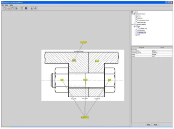
Figure 4: The Designers’ Workbench
op_temp_limit(MaterialMaxTemp, EnvironTemp) :-EnvironTemp =< MaterialMaxTemp.
Using the values of?arg1and?arg2, the query
op_temp_limit(MaterialMaxTemp, EnvironTemp).
is formed, and checked. This process is repeated for each set of values returned by the RDQL query, and for each constraint that has been specified.
6
Additional features of the Designers’
Workbench
A screenshot of the Designers’ Workbench is shown in Figure 4, with closeups of the main panels in Figure 5. In this section, we describe the system’s additional features.
6.1
Graph-based display of configuration
Figure 5: Closeups of the Designers’ Workbench panels: the feature ontology (left), and properties of selected feature (right)
— the designer can “mark up” an existing drawing or construct a configuration without a drawing. Features can be selected from an ontology. Features that are added by the designer are shown as labels overlaying the background draw-ing. Properties that connect features are represented by arcs. Features can be selected, and their properties viewed and modified using the table displayed be-neath the ontology. Datatype properties are set by typing values into the field, whereas object properties are set using a drop down list of values representing the valid possibilities for the property. For example, if the propertyhas_bolt
is specified to have range of classBolt,the list will consist only of instances ofBolt.
6.2
Checking incomplete configurations
Before checking constraints, it is not necessary to specify values for every de-fined property of every feature. Instead, the designer can fill in values for whichever properties he or she desires, and request a constraint check. The RDQL query will only return results for the features that have sufficient values specified, so that only certain constraints will be checked. This allows designers to operate in an exploratory way, defining small parts of a configuration, check-ing them, and then gradually extendcheck-ing the configuration until it is complete.
6.3
Constraint rationales
7
Preliminary evaluation
In order to get feedback on the Designers’ Workbench an informal interview was carried out with an engineer with six years experience at Rolls-Royce. The format of the interview was: an overview of the system was given by the developer, followed by the engineer attempting a series of tasks, and finally a discussion of the pros and cons of the system took place. The main findings were:
1. the interface was intuitive to use, although some details needed to be refined (for example, the exercise revealed some mismatches between the original ontology and the domain);
2. it was reasonably straightforward to add features to a design, although the engineer would have preferred textual items rather than icons. This could be implemented as an option that the user can set as required;
3. the engineer prefers that constraint checks are performed automatically, and an error message pops up, rather than the current arrangement of the user requesting that constraint checks be performed. Again, this could be an option that the user could enable or disable as required;
4. the engineer requested an additional feature, namely that links to previous designs or documents referring to similar features or issues be provided, enabling the user to find relevant past material quickly. Currently, pre-vious designs or documents can be searched, but only by a text-based search;
5. the engineer did not currently use software that provides the same func-tionality as the Designers’ Workbench.
Clearly, point 4 provides the most challenge. To find previous documents relating to particular features will require that the documents are annotated with reference to the same ontology as used by the Designers’ Workbench. This means that authors of these documents must be provided with editors that will enable them to make these annotations as painlessly and as automatically as possible.
8
Future work
The Designers’ Workbench is still at an early stage of development. In this section we describe some possible future avenues of research.
8.1
Propagation of values
only tentatively selected a value for a particular property, and may deliberately wish to select an incompatible value for another property. A possible solution would be to display all the values in the domains for the designer to choose from, but highlight in some way the values that are incompatible with the cur-rently selected values for other properties. The implementation of this feature will require the use of the constraint solving libraries of SICStus to maintain variable domains and perform propagation, rather than the simple predicate checking that is used currently.
8.2
Functional descriptions
The current version of Designers’ Workbench does not deal explicitly with the functions of features. (Functions have been described using ontologies by Iwasaki et al. [IFVC93] and Kitamura et al. [KSNM02].) Nor does it deal with the various possible different states of features; for example, a shaft will have to operate successfully at different temperatures, pressures and rotational speeds. Adding functions to the Designers’ Workbench will allow users to specify the intended functions of each feature, or group of features. Using an ontology of functions should allow for a fairly straightforward integration with the current system.
8.3
Design rationale storage (argumentation)
It would be very useful to capture and store the reasoning that the designer performs during the configuration process (design rationale capture). More details on processing design rationales can be found in [BS96] and [BW03]. Designers can examine current and past solutions to find out the reasons for particular decisions, why alternatives were discarded, and avoid repeating past mistakes.
8.4
Constraint input
8.5
Ontology change
Occasionally the available features described in the ontology may have to be increased (new parts or techniques become available), or decreased (obsolete parts removed). It is also possible that extensive changes may be made to naming conventions, or the arrangement of the feature class hierarchy. It is important to ensure that:
• previous designs can still be accessed using Designers’ Workbench (pos-sibly by recording the original ontology as part of each design);
• that existing constraints can be kept up to date.
A constraint that is defined on a class of features will automatically apply to a new subclass of that class. The problem of removals can be overcome by retaining the class, but flagging it in some way as obsolete. The most difficult situation will be the restructuring of a class hierarchy, which may require complex processing to ensure that existing constraints will still apply where necessary.
9
Summary
The Designers’ Workbench allows designers to specify a configuration by se-lecting features from an ontology. Parameters of a feature can be specified by setting datatype property values, and the connections to other features are specified with objecttype properties. Constraints are defined on classes of fea-tures, but are applied to instances of features. A configuration can be checked for constraint violations at any time, even if some features are only partially specified. We have concentrated on assisting a human designer by checking constraints, rather than attempting to find solutions automatically. Constraint checking is performed by searching the configuration for applicable features, and passing the values of appropriate properties to a SICStus Prolog checker. A graphical display enables the designer to easily add new features, set property values, and perform constraint checks.
Acknowledgements
References
[BOS90] J. Bowen, P. O’Grady, and L. Smith. A constraint programming language for life-cycle engineering. Artificial Intelligence in Engi-neering, 5(4):206–220, 1990.
[Bro98] D. C. Brown. Defining configuring.AI EDAM, 12:301–305, Septem-ber 1998.
[Bro02] D. C. Brown. Functional, behavioral and structural features. In J. C. Borg and P. Farrugia, editors,Proc. KIC5: 5th IFIP WG5.2 Workshop on Knowledge Intensive CAD, Malta, July 2002. [BS96] S. Buckingham Shum. Design argumentation as design rationale. In
A. Kent and J. G. Williams, editors,The Encylopedia of Computer Science and Technology, pages 95–128. Marcel Dekker, Inc., 1996. [BW03] R. Bracewell and K. Wallace. A tool for capturing design rationale.
InICED03, 14th International Conference on Engineering Design, pages 185–186, Stockholm, Sweden, 2003.
[CJB99] B. Chandrasekaran, J. R. Josephson, and V. R. Benjamins. What are ontologies and why do we need them? IEEE Intelligent Systems, 14(1):20–26, Jan/Feb 1999.
[DAM] The darpa agent markup language homepage. http://www.daml.org/.
[GHP01] P. Gray, K. Hui, and A. Preece. An expressive constraint lan-guage for semantic web applications. In IJCAI-01 Workshop on E-Business and the Intelligent Web, pages 46–53, Seattle, USA, August 2001.
[IFVC93] Y. Iwasaki, R. Fikes, M. Vescovi, and B. Chandrasekaran. How things are intended to work: Capturing functional knowledge in device design. In IJCAI-93, pages 1516–1522, 1993.
[JEN] Jena - a semantic web framework for java. http://jena.sourceforge.net/index.html.
[JM03] U. Junker and D. Mailharro. The logic of ilog (j)configurator: Com-bining constraint programming with a description logic. In Proceed-ings of IJCAI’03 Workshop on Configuration, 2003.
[KSNM02] Y. Kitamura, T. Sano, K. Namba, and R. Mizoguchi. A func-tional concept ontology and its application to automatic identifi-cation of functional structures. Advanced Engineering Informatics, 16(2):145–163, April 2002.
[Lab03] F. Laburthe. Constraints over ontologies. InProceedings of CP2003, 2003.
[LC02] L. Lin and L.-C. Chen. Constraints modelling in product design.
Journal of Engineering Design, 13(3):205–214, September 2002. [LFB96] Jinxin Lin, M. Fox, and T. Bilgic. A requirement ontology for
engineering design. Concurrent Engineering: Research and Appli-cations, 4(4):279–291, September 1996.
[MF89] S. Mittal and F. Frayman. Towards a generic model of configuration tasks. In Proceedings of the Eleventh International Joint Confer-ence on Artificial IntelligConfer-ence (IJCAI-89), pages 1395–1401, San Francisco, CA, 1989. Morgan Kaufmann.
[MF90] S. Mittal and B. Falkenhainer. Dynamic constraint satisfaction problems. InAAAI-90: The Eighth National Conference on Artifi-cial Intelligence, pages 25–32. MIT Press, 1990.
[MW98] D. L. McGuinness and J. R. Wright. Conceptual modelling for configuration: A description logic-based approach.Artificial Intelli-gence for Engineering Design, Analysis and Manufacturing, 12:333– 344, 1998.
[SF96] D. Sabin and E. C. Freuder. Configuration as composite constraint satisfaction. In George F. Luger, editor, Proceedings of the (1st) Artificial Intelligence and Manufacturing Research Planning Work-shop, pages 153–161. AAAI Press, 1996, 1996.
[SFH98] M. Stumptner, G. E. Friedrich, and A. Haselb¨ock. Generative constraint-based configuration of large technical systems. Artificial Intelligence for Engineering Design, Analysis and Manufacturing, 12:307–320, 1998.
![Figure 2: A bolted joint [image from French, Vierck and Foster, “EngineeringDrawing and Graphics Technology”, McGraw-Hill Inc.]](https://thumb-us.123doks.com/thumbv2/123dok_us/8517409.352001/6.595.238.409.311.454/figure-french-vierck-foster-engineeringdrawing-graphics-technology-mcgraw.webp)