UNIVERSITI TEKNIKAL MALAYSIA MELAKA
PRODUCT IMPROVEMENT OF CORNELL CFF-12P FAN BY
DESIGN FOR ASSEMBLY METHOD (BOOTHROYD
DEWHURST)
This report submitted in accordance with requirement of the Universiti Teknikal Malaysia Melaka (UTeM) for the Bachelor’s in Manufacturing Engineering
Technology (Product Design)(Hons)
by
SITI AZUREEN BINTI SAPARDIN B071310381
911007-14-6262
UNIVERSITI TEKNIKAL MALAYSIA MELAKA
BORANG PENGESAHAN STATUS LAPORAN PROJEK SARJANA MUDA
TAJUK: PRODUCT IMPROVEMENT OF CORNELL CFF-12P FAN BY DESIGN
FOR ASSEMBLY METHOD (BOOTHROYD DEWHURST)
SESI PENGAJIAN: 2016/17 Semester 1
Saya SITI AZUREEN BINTI SAPARDIN
mengaku membenarkan Laporan PSM ini disimpan di Perpustakaan Universiti Teknikal Malaysia Melaka (UTeM) dengan syarat-syarat kegunaan seperti berikut:
1. Laporan PSM adalah hak milik Universiti Teknikal Malaysia Melaka dan penulis. 2. Perpustakaan Universiti Teknikal Malaysia Melaka dibenarkan membuat salinan untuk
tujuan pengajian sahaja dengan izin penulis.
3. Perpustakaan dibenarkan membuat salinan laporan PSM ini sebagai bahan pertukaran antara institusi pengajian tinggi.
4. **Sila tandakan ( )
SULIT
(Mengandungi maklumat TERHAD yang telah ditentukan oleh organisasi/badan di mana penyelidikan dijalankan)
Alamat Tetap:
Lot 3164, Lorong Setia 5, Batu 18 1/4,
Kuang, 48050
Rawang, Selangor
Tarikh: ________________________
Disahkan oleh:
Cop Rasmi:
Tarikh: _______________________ TERHAD
TIDAK TERHAD
(Mengandungi maklumat yang berdarjah keselamatan atau kepentingan Malaysia sebagaimana yang termaktub dalam AKTA RAHSIA RASMI 1972)
FAKULTI TEKNOLOGI KEJURUTERAAN
Tel : +606 234 6623 | Faks : +606 23406526
Rujukan Kami (Our Ref) : Rujukan Tuan (Your Ref) :
09 DIS 2016
Pustakawan
Perpustakaan UTeM
Universiti Teknikal Malaysia Melaka Hang Tuah Jaya,
76100 Durian Tunggal, Melaka.
Tuan/Puan,
PENGKELASAN LAPORAN PSM SEBAGAI SULIT/TERHAD LAPORAN PROJEK SARJANA MUDA TEKNOLOGI KEJURUTERAAN PEMBUATAN (REKABENTUK PRODUK): SITI AZUREEN BINTI SAPARDIN
Sukacita dimaklumkan bahawa Laporan PSM yang tersebut di atas bertajuk
“PRODUCT IMPROVEMENT OF CORNELL CF-12P FAN BY DESIGN FOR ASSEMBLY METHOD (BOOTHROYD DEWHURST)” mohon dikelaskan sebagai *SULIT / TERHAD untuk tempoh LIMA (5) tahun dari tarikh surat ini.
2. Hal ini adalah kerana IANYA MERUPAKAN PROJEK YANG DITAJA OLEH SYARIKAT LUAR DAN HASIL KAJIANNYA ADALAH SULIT.
Sekian dimaklumkan. Terima kasih.
Yang benar,
________________
Tandatangan dan Cop Penyelia
* Potong yang tidak berkenaan
DECLARATION
I hereby, declared this report entitled “Product Improvement of Cornell CFF-12P Fan by Design for Assembly Method (Boothroyd Dewhurst)” is the results of my
own research except as cited in references.
Signature : ……….
Author’s Name : SITI AZUREEN BINTI SAPARDIN
APPROVAL
This report is submitted to the Faculty of Engineering Technology of UTeM as a partial fulfillment of the requirements for the degree of Bachelor of Manufacturing Engineering Technology (Product Design) with Honours. The member of the supervisory is as follow:
i
ABSTRAK
Kaedah mereka bentuk pemassangan adalah rangka kerja yang ditubuhkan yang
digunakan untuk mencipta produk. Dengan melaksanakan kaedah mereka bentuk
pemasangan dalam projek ini, rekabentuk analisis yang dijalankan untuk kipas
Cornell CFF 12-P. Aspek-Aspek penting yang perlu di pertimbangkan adalah proses
pemasangan, kesukaran pengendalian dan kesukaran pemasangan. Masalah yang
terdapat pada kipas ini adalah terdapat banyak penggunaan skru pada pemasangan
produk ini. Objektif projek ini adalah untuk mengurangkan bahagian produk pada
masa yang sama mengekalkan fungsi kipas, untuk menganalisis perbandingan di
antara kecekapan reka bentuk asal dan reka bentuk baru dan untuk optimumkan
penyelesaian yang lebih baik daripada kipas yang sedia ada dipasaran berdasarkan
garis panduan reka bentuk pemasangan. Berdasarkan kajian, terbukti masa
pemasangan dapat dijimatkan dari 52.31 s kepada 15.8 s. Indeks reka bentuk
pemasangan juga menunjukkan peningkatan dari 0.6 kepada 6.3. Kelebihan
menggunakan kaedah reka bentuk pemasangan telah dibuktikan dalam reka bentuk
baru kipas Cornell CFF-12P. kecekapan reka bentuk yang telah dikira secara manual
ii
ABSTRACT
Design for Assembly method is an established framework that is used to create a
product. By implement DFA method in this project the design analysis is conducted
for Cornell CFF-12P fan. The important aspects that need to be considered is
assembly process, handling difficulties & insertion difficulties. The problem with
this fan is a lot of fastener use to assemble the product. The objectives of this project
is to reduce part while maintaining the function of fan, to analyse the comparison
between the design efficiency original design and improved design and to provide
optimised solution that better than existing fan in market based on DFA guidelines.
Based on study, it is proven that the assembly time is save from 52.31 s to 15.8 s. the
DFA index also show improvement from 0.6 to 6.3. The advantages of using DFA
method has been proved in redesign the Cornell CFF-12P fan. The design efficiency
iii
DEDICATION
To my beloved husband, son, parents and family thank you for being supportive and
iv
ACKNOWLEDGEMENT
First and foremost I offer my sincerest gratitude to my adorable supervisor,
Madam Nurul Ain Binti Maidin, who has being very supportive share knowledge
and for being very patience. I attribute the level of my without her encouragement,
this project would not have been completed or written. One simply could not wish
for a friendlier supervisor
In my daily life 1 have been blessed with my beloved husband, Mr
Mohammad Amirul bin Abdullah for helping and be by my side whenever I felt that
I am not the best and not to forget my son, Muhammad Amir Mukhriz bin
Mohammad Amirul for always make me wants to do my best.
My special thanks to my beloved parents Mr Sapardin bin Hj Kamaruddin
and Mrs Faridah Hanum binti Isa for all the sacrifice.
v
TABLE OF CONTENTS
Abstrak i
Abstract ii
Dedication iii
Acknowledgement iv
Table of Content v
List of Tables ix
List of Figures x
List Abbreviations, Symbols and Nomenclatures xiii
CHAPTER 1: INTRODUCTION 1
1.1 Background 1
1.2 Problem Statement 2
1.3 Objectives 2
1.4 Scopes of Projects 2
1.5 Organizations of Projects 3
1.6 Expected Result 3
CHAPTER 2: LITERATURE REVIEW 4
2.1 Design for Manufacturing and Assembly (DFMA) 4
vi
2.3 DFA Methods 6
2.4 DFA Guidelines 8
2.5 DFA Product Simplification Software (BDI) 10
2.6 Boothroyd-Dewhurst Method 10
2.7 History of Fan 11
2.8 Types of Fan 13
2.9 Cornell CFF-12P 14
2.10 CAD Modelling 15
Summary Literature Review 16
CHAPTER 3: METHODOLOGY 17
3.1 Introduction 17
3.2 Flow Chart 18
3.3 Formulation of Project 20
3.4 Research for Literature Review 20
3.5 Part Identification of Fan 20
3.5.1 Survey 20
3.5.2 Bill of Material 25
3.5.3 Detail Design (Original Design) 26
3.5.4 Assembly Drawing 32
3.5.5 Exploded View 33
vii
3.7 Redesign of Fan 36
3.7.1 Details Design (Redesign) 37
3.7.2 Assembly Design (Redesign) 42
3.7.3 Exploded View 43
3.7.4 Bill of Material (Redesign) 44
3.8 Comparison Design between Original and Redesign 44
3.9 Generate Project Report 46
CHAPTER 4: RESULT AND DISCUSSION 47
4.1 Boothroyd Dewhurst Analysis 47
4.1.1 Original Design 47
4.1.2 Redesign 49
4.1.3 Other Related Information 50
4.2 Boothroyd Dewhurst Software 51
4.2.1 DFA Analysis of original Design 51
4.2.2 DFA Analysis of Redesign 53
4.3 DFA Analysis and Discussion 56
4.4 Comparison of DFA Analysis and Manual Calculation 58
viii
CHAPTER 5: CONCLUSION AND RECOMMENDATION 61
5.1 Conclusion 61
5.2 Recommendation for Future Work 62
REFERENCES 63
ix
LIST OF TABLES
Table 2.1 Design guidelines
Table 3.1 Bill of material original design
Table 3.2 Bill of material redesign
Table 4.1 Manual handling and insertion for original design
Table 4.2 Manual handling and insertion for redesign
Table 4.3 Comparison of original design and redesign for manual handling and
insertion
Table 4.4 DFA analysis of Cornell CFF-12P part
Table 4.5 DFA analysis result of original design of Cornell CFF-12
Table 4.6 DFA analysis for redesign (base and stand, front gril, back grill) of
Cornell CFF-12P
Table 4.7 DFA analysis result for redesign of Cornell CFF-12P
Table 4.8 Comparison of DFA analysis for original design & redesign of
Cornell CFF-12P
Table 4.9 Table of comparison between DFA analysis and manual calculation
x
LIST OF FIGURES
Figure 2.1 Typical steps taken in simultaneous engineering study using DFMA
Figure 2.2 Manual handling and manual insertion
Figure 2.3 Electric fans early 1880s
Figure 2.4 silver swan fans
Figure 2.5 Cornell CFF-12P fan
Figure 3.1 Percentage of knowing about Cornell CFF-12P
Figure 3.2 Percentage that agree a lot of screw use to fasten Cornell CFF-12P
Figure 3.3 Percentage that agree to fasten screw take time
Figure 3.4 Percentage that prefer fan with many screw
Figure 3.5 Percentage that agree to use snap fit to replace screw
Figure 3.6 Percentage that agree by using snap-fit can reduce time
Figure 3.7 Percentage that agree by combining base and stand can reduce
production time & cost
Figure 3.8 percentage that agree by using snap-fit and combination base and
stand can save production time and cost.
Figure 3.9 Drawing of base part
Figure 3.10 Drawing of stand part
Figure 3.11 Drawing of fan housing part
Figure 3.12 Drawing of back grill part
Figure 3.13 Drawing of front grill part
xi
Figure 3.15 Assembly drawing of Cornell CFF-12P
Figure 3.16 Exploded view of Cornell CFF-12P
Figure 3.17 Structure chart of original design
Figure 3.18 Structure chart of redesign
Figure 3.19 The evaluation properties interface in DFA analysis
Figure 3.20 Drawing of combination base and part (redesign)
Figure 3.21 Drawing of fan housing (redesign)
Figure 3.22 Drawing of fan back grill (redesign)
Figure 3.23 Drawing of fan front grill (redesign)
Figure 3.24 Drawing of snap-fit that is used
Figure 3.25 Assembly drawing of redesign Cornell CFF-12P
Figure 3.26 Exploded View of redesign Cornell CFF-12P
Figure 3.27 Original design of base and stand with fastener
Figure 3.28 Redesign combination of base and stand without fastener
Figure 3.29 Original design of front grill & back grill with fastener
Figure 3.30 Redesign of front grill & back grill with snap-fit
Figure 4.1 The breakdown of time per product for original design of the Cornell
CFF-12P (DFA)
Figure 4.2 The breakdown of time per product for redesign of the Cornell
CFF-12P (DFA)
Figure 4.3 The breakdown of time per product for original and redesign of
Cornell CFF-12P
xii
Figure 4.5 Comparison total assembly time between manual calculation and
DFA analysis
Figure 4.6 Comparison design efficiency between manual calculation and DFA
xiii
LIST OF ABBREVIATIONS, SYMBOLS AND
NOMENCLATURE
DFMA = Design for Manufacturing and Assembly
1
CHAPTER 1
INTRODUCTION
These days, several of fan model are accessible with various brand and
quality this made the component of the fan to appear as something else and unique
depends on the designer and company intention to be focused. In any case, the
manufacturing process is the essential things to be considered as it will influence the
cost of the product itself. Thus, this project focused on analysing the design of a fan
in order to diminish cost then enhance the manufacturing and assembly process with
a new design of a fan after the analysis. This chapter fundamentally clarify how the
project is being made starting from the background study, problem statement,
objectives, scope, and organization of the project and lastly result expectations.
1.1 Background
Nowadays, there are a lot of process which all influence product cost, quality
and productivity of system. This is because a lot of product is made up of fasteners
and redundant features. Design for Manufacturing and Assembly (DFMA) method
can ease the manufacture of the part will form a product and ease the assembly. It is
to simplify product structure, to reduce manufacturing and assembly cost and to
quantify improvements that eliminates waste or efficiency in a product design. The
aim of this project is to improve the design and analyse of the efficiency and function
2
1.2 Problem Statement
Some of the fan uses a lot of fasteners and redundant features. As a solution,
the part is reducing but function remains the same. Analysis need to be constructing
to make a comparison between the original design efficiency and after redesign
efficiency. Hence, to show the problem can be overcome, a prototype of a new
design will be built. This is to show the product still functioning even reducing its
part.
1.3 Objectives
(i) To reduce part while maintaining the function of fan.
(ii) To analyse the comparison between the design efficiency original design and
improved design.
(iii) To provide optimised solution that better than existing fan in market based on
DFA guidelines.
1.4 Work Scope
(i) Conduct survey toward 100 respondents to gain the information about
assemble problem for this fan.
(ii) Improve the design (redesign) by using SolidWork.
(iii) Analyse the design efficiency (original design and redesign) by using DFA
3
1.5 Organization of the Project
(i) Chapter 1: Introduction
This chapter will simply introduce about the project. This chapter contains
introduction, problem statements, objectives, scopes of project and expected
results.
(ii) Chapter 2: Literature Review
This chapter shows about the studies and research that relevant to the project.
(iii) Chapter 3: Methodology
This part will show the canvas about the project methodology used in this
project.
(iv) Chapter 4: Results
This part will state out the result that be obtained.
(v) Chapter 5: Discussions
This chapter will talk about the discussion of the result of the project.
(vi) Chapter 6: Conclusion
This chapter will discuss about the summarization of the project and the
major conclusion of the project.
1.6 Expected Result
4
CHAPTER 2
LITERATURE REVIEW
As the time flies an associations need to learn so as to enhance their
adaptability and efficiency toward future. In spite of the fact that this thought with
the assistance of new technologies and philosophies of insight of contend with
different competitors truly could improve the development process with good results
to achieve target. As for now, there are a considerable of tools that could be used to
help production team to solve their issue at an early stage. Subsequently, this chapter
will review the past research from different sources with reference
2.1 Designs for Manufacturing and Assembly (DFMA)
Design for manufacturer and assembly (DFMA) is a tool that aids in
minimizing production cost by separating the product down to be the least difficult
components and parts. Concurrent Engineering (CE) is proposed to bring about
developers from the beginning, to consider plan, quality, cost, user demand and all
component of product cycle from origination to transfer. Both of this Production
Oriented Design (DFMA and CE) could run activities all the while in a parallel
structure. They were using simulation method that could give a completely
understanding among colleague to discover errors along the procedure and fix it
before the development ends
There are two major concept in DFMA process in which design for assembly
(DFA) and also design for manufacturing (DFM). DFA is a design of the product for
5
multidisciplinary teams to assess and validate product design as for the manufacturer
and assembly of its components parts. In the meantime, DFM is to design that
depends on lessening the cost of production and time to market for a product, while
maintaining fitting level of quality the material and tooling side of the new product.
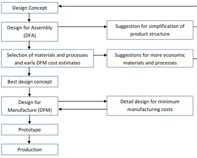
[image:23.595.115.510.216.532.2]Consequently, DFMA refers to working on booth concepts together.
Figure below shows the typical steps taken in DFMA study using DFMA software.
(Sources: Boothroyd, G., 1994. Product Design for Manufacturing and Assembly, Computer Aided
Design Volume 26.)
Figure 2.1: Typical steps taken in simultaneous engineering study using DFMA
DFMA can be used successfully to diminish part number in the assembly that
brings to rearrange the assembly process, lower fabricating, overhead cost, and
minimize assembly time and enhance quality by lessening the potential outcomes for
introducing a defect. Additionally the amount of labour can be diminished once the
component of parts gets to be less and less complex assembly processes. At the point Design Concept
Design for Assembly (DFA)
Selection of materials and processes and early DFM cost estimates
Detail design for minimum manufacturing costs Best design concept
Suggestion for simplification of product structure
Suggestions for more economic materials and processes
Prototype
6
when the part number had been decreased, naturally the development cycle get to be
shortened as the philosophy empowers simplifying the design and using standardize
component whenever possible. The advantages of Boothroyd & Dewhurst DFMA
system in reducing the number of part count. Reducing part count can saves
assembly, save labour, inventory floor space, documentation and administration.
2.2 Designs for Assembly (DFA)
By and large, there are two objective of DFA in which to minimize part
number and to have remaining parts of a nature that they are effortlessly assembled
together. The DFA technique fulfilled the objective by:
(i) Providing an apparatus for the designer and even design group which
guarantees that thought of product complexity and assembly happen at the
earliest design stage. This wipes out the danger of concentrating too much of
the entire things during early design on product function with insufficient
regard for product cost and competitiveness.
(ii) Guiding the designer to simplify the product so that the cost of assembly and
parts can be spare similarly.
(iii) Gathering data ordinarily possessed by the accomplished design engineer and
arranging it advantageously for use by less-experienced designers.
(iv) Forming a database that involves assembly times and cost factors for
variables design situations and production conditions
2.3 DFA Methods
The analysis of a product design for simplicity of assembly depends to a huge
extent on whether the product is to be assembled manually, fixed or hard automation,
soft automation (robotic) or a mix of these. The reasons of implement this method is