DESIGN AND DEVELOPMENT OF MICROSTRIP PATCH ANTENNA FOR GSM APPLICATION
SADDAM ABDULLAH QASEM ABDO
This report is submitted in partial fulfilment of the requirement for the award of Bachelor of Electronic Engineering (Wireless Communication) With Honors
Faculty of Electronic and Computer Engineering UNIVERSITI TEKNIKAL MALAYSIA MELAKA
DECLARATION
I hereby declare that this report entitled “Design and Development of Microstrip Patch Antenna for GSM Application” is the result of my own work and that, to the best of my knowledge and believe. It contains no material previously published or written by another person except for quotes as cited in the references and also no material which to a substantial has been submitted for the award of any other degree or diploma of a university or other institution of higher learning.
Signature: ...
Name : Saddam Abdullah Qasem Abdo
ii
APPROVEL
“I hereby declare that I have read through this report entitled “Design and Development of Microstrip Antenna for GSM Application” and found that it is sufficient to a comply the partial fulfilment for awarding the degree of Bachelor of Electronics Engineering (Telecommunication Engineering) with Honours”
Signature: ………
Supervisor: En. Imran bin Mohd Ibrahim
iii
DEDICATION
iv
ACKNOWLEDGEMENT
First and foremost, I would like to praise to Allah S.W.T for giving me a little strength and ability to do my final year project and eventually succeed to complete my report as required. I would like to express my gratitude to my supportive supervisor, EN. Imran Bin Ibrahim for providing his insightful knowledge and valuable assistance throughout this project under his guidance.
I would like to take the chance to thank all lecturers who taught me in the past four years and had a great contribution that qualify me to do my final year project. I would like to thank Dr. Kok Swee Leong, and lectures who arrange for INOTEK exhibition, for their efforts in providing information and cooperation to help students achieving the goals of final year projects. I would like to thank the technicians, Mr. Imran bin Mohamed Ali and Mr Mohd Sufian bin Abu Talib for their cooperation during fabrication and measurement processes. A particular line of appreciation is extended to my parents, for their unflagging encouragement and support throughout my studies. Their suggestions and ideas were very useful as it helped me to successfully complete my final year project and studies. I would like to thank all senior students who helped and encouraged me though out my studies. Thanks as well to all my acquaintances for their counsel and knowledge they provide to me. Lastly, my thanks as well extend to whoever supported me directly or indirectly in doing my final year project and throughout my studies.
v
ABSTRACT
In microstrip patch of short-range communication system, an antenna is very important part that used to enhance and strength the signals. However, in many cases of short-range communication system, the gain of the designed antenna that used is quite low so that it results in low power and affect the target frequency to transmit and receive signal in well condition. This project aims to design an antenna that provides a high gain so that the transmitted signal and efficiency of radiating the signal would be increased. A small microstrip patch antenna is designed in CST Studio Suite software. Optimization in CST software for the microstrip antenna designed is done prior to fabrication process that is carried in the laboratory. Once the simulation and fabrication processes are done, comparison of the antennas performance is carried, in terms of antenna parameters such as gain, return loss, bandwidth, efficiency and radiation pattern.
vi
ABSTRAK
Dalam mikrostrip patch sistem komunikasi jarak dekat, antena adalah bahagian yang sangat penting yang digunakan untuk meningkatkan dan kekuatan isyarat. Walau bagaimanapun, dalam banyak kes sistem komunikasi jarak dekat, gandaan antena direka yang digunakan adalah agak rendah supaya menghasilkan tenaga yang rendah dan menjejaskan kekerapan sasaran untuk menghantar dan menerima isyarat dalam keadaan baik. Projek ini bertujuan untuk mereka bentuk antena yang menyediakan keuntungan yang tinggi supaya isyarat dan kecekapan terpancar isyarat yang dipancarkan akan meningkat. A kecil antena mikrostrip patch direka dalam perisian CST Studio Suite. Optimization dalam perisian CST untuk antena mikrostrip yang direka dilakukan sebelum proses fabrikasi yang dijalankan di makmal. Setelah proses simulasi dan fabrikasi selesai, perbandingan prestasi antena itu dijalankan, dari segi parameter antena seperti keuntungan, kehilangan pulangan, jalur lebar, kecekapan dan corak radiasi.
vii
TABLE OF CONTENTS
DECLARATION i
APPROVEL ii
DEDICATION iii
ACKNOWLEDGEMENT iv
ABSTRACT v
ABSTRAK vi
TABLE OF CONTENTS vii
LIST OF TABLES x
LIST OF FIGURES xi
CHAPTER 1
1 INTRODUCTION 1
1.1 Background 1 1.2 Problem Statement 3 1.3 Objectives 4
2 LITERATURE REVIEW 5 2.1 Introduction 5 2.2 GSM Technology (Global System in Mobile Communication) 5
2.2.1 Historical Background 6
2.2.2 Microstrip Antennas Requirement 6
2.2.3 GSM Advantages 7
2.2.4 Disadvantages of GSM 8
2.2.5 Spectrum of Frequency 8
2.2.6 Global System of Mobile Applications 10 2.3 Selection of Antenna for GSM Antenna 11
2.4.1 Microstrip Patch Antennas 12
viii
2.4.5 Feeding Techniques 15
2.3.5.1 Coaxial Feed 16
2.3.5.2 Microstrip Line Feed 17
2.4 Previous Work 18
3.4.1 New GSM Antenna for Global System of Mobile Communication Applications 18 3.4.2 Design and Analyze Two Single Rectangular Patch Antennas with a Slot 19 3.4.3 Investigate New Microstrip Antenna Structure for GSM 1800 Band and WIMAX System Applications 20 3 METHODOLOGY 24 3.1 Design Methodology 24
3.2 Flow Chart 26
3.3 Design Software 26
3.4 Simulation Process 27
3.4.1 Antenna Specifications 27 3.4.2 Small Patch Antenna Design 28 3.4.3 Transmission Line for Small Patch Antenna 29 3.4.4 Feeding of Microstrip Patch Antenna 30 3.4.5 Design Parameter of Rectangular Microstrip Antenna 30 3.5 Fabrication Process 32
3.6 Antenna Measurement 33
4.2.1 Cable Loss Measurement 33 4.2.2 Radiation Pattern 33 4.2.3 Power Receiver for Antenna 34 4.2.4 Testing the Antenna Signal 34 3.7 Conclusion 35
4 RESULTS AND DISCUSSION 36 4.1 Introduction 36
4.2 Antenna Simulation Result 36
4.2.1 Return Loss 36
ix
4.2.3 Radiation Pattern and Directivity 38
4.2.4 Impedance Matching 38
4.3 Measurement Result of the Antenna 39
4.3.1 Return loss 39
4.3.2 Gain 40
4.3.3 Radiation pattern 41
4.4 Conclusion 43
5 CONCLUSION AND RECOMMENDATION 44 5.1 Conclusion 44 5.2 Recommendation 45
x
LIST OF TABLES
TABLE TITLE PAGE
2.1 The Advantages and Benefits of GSM 9
3.1 The Design Characteristic of the Antenna 27
3.2 Design Specifications of Patch Antenna 27
xi
LIST OF FIGURES
Figures TITLE PAGE
2.1 The system topology of GSM 7
2.2 A Typical Microstrip Antenna 11
2.3 Basic Microstrip Patch Antenna Shapes Commonly Used In Practice.
12
2.4 Rectangular Microstrip Patch Antenna 14
2.5 Coaxial Feed 16
2.6 Micro Strip Feed 17
2.7 Microstrip Feed and Substrate Thickness 17
2.8 The Geometry of the Proposed GSM Antenna: (a) front view (b) back view
18
2.9 Simulated (a) Return Loss with parasitic element and (b) Return Loss without Parasitic element of the proposed antenna:
20
2.10 Geometry of Dual band Microstrip Patch Antenna 21 2.11 The Simulated and Measured Results for the Proposed Antenna 22
3.1 The Flow Chart of Project 26
3.2 The Side View of the Antenna 27
3.3 Front View of Designed Antenna 30
3.4 The Prototype of Small Patch Microstrip Antenna 32
3.5 Cable Loss Measurement 33
3.6 Testing the Antenna Signal 34
4.1 Comparison Between Simulation and Measurement 37
4.2 Realized Gain of the Simulated Antenna 38
4.3 Radiation Pattern in Polar Form 38
4.4 The Impedance Matching of Small Microstrip Patch Antenna 39
CHAPTER 1
INTRODUCTION
1.1 Background
Wireless communication technology has become more important to everybody in day life. There are two main parts in wireless communication which are physical part and the application system. As we know that the antenna is from the important components in the system of physical to convert the electrical energy into the air for signal transmission. From the properties of microstrip antenna are small size, , low profile, low-cost fabrication, conformability, lightweight, ease of installation and integration with feed networks and one of the serious limitations of these antennas are narrow bandwidth. So it can be seen that the characteristics as it limits the frequency ranges over which the antenna can perform well [2]. The emergence of technical improvements has enabled a large number of new services. The improvement of such these technical has many features to develop the world utilities such the wide used application GSM and CDMA. For supporting such application which requires the speed internet connection, high definition video, and other application, there should need high data rate.
In modern wireless of communication system with the increasing of other wireless applications that requires low cost and high performance multiband antennas, this demand a high performance in multi-standard communication systems that led the antenna research and studies in many directions. On of this design of multiband microstrip antenna is Global system of mobile communication (GSM).
Transmission line of microstrip in dielectric thickness is as follow;
Dielectric constant Height of dielectric
2
2
Width of signal line w mm
Thickness of signal line t mm
In the designed parameters we have obtained the initial results for VSWR which is 2:1 for 5.8 and 2:1 for 26, for the percent bandwidth is 11.5 %, minimum gain = -6db, radiation pattern which we are going to plot it by using SCT software and we got the return loss which is less than 10 dBi [1].
∆𝑊 = 𝑡(1+1/ℇ𝑟
2𝜋 )𝑙𝑛 [ 10.82 √(𝑡 ℎ) 2 +(𝑤1/𝜋
𝑡+1.1 )
2
]
(2.1)
𝑤,= 𝑤 + ∆𝑤 (2.2)
From the equation above; we can analyze that the transmission line, Characteristic impedance and Effective relative permittivity can be increased if the corresponding bandwidth or the SNR (also defined as transmission power). However, the transmission power cannot easily increase since there are some devices such as portable devices are battery poweredand also potential interference can be avoided. Hence, in order achieve the greater data rate, we need to increase the bandwidth. In addition to telephony, services for digital fax and data transmission were already defined back when GSM standards were created. Apart of pure voice transmission, GSM specifications, for example, providing a broad diversified spectrum of data services and fax. Furthermore, the first data services in GSM networks were circuit-switched, asynchronous data services (CSD, Circuit Switched Data), as those long used for remote data transmission in analog telephone networks. Only specific, international, standardized communication protocols are used for dial-up and transmitting data. Therefore, data can be exchanged with all conventional receivers, provided that the devices used comply with these international applicable standards
3
3
unified Europe were increasingly unimportant, but there was also a very limited market for each type of equipment, so economies of scale and the subsequent savings could not be realized. However, there are necessary for developers as well as engineers to design a system that has capacity to support and handle the larger bandwidth. One of the components of this system is antenna which is considered as most important design element. If the antenna isn’t well designed, then there will be degradation in the data signal before it even reaches the end users. Due to this reason, engineers are done many researches on design an antenna that will compatible with GSM application. There are many types of antenna that can be applied in order to achieve the GSM antenna, however in this project, we focusing on the microstrip patch antenna. Microstrip patch antenna becomes very popular in any antenna design nowadays since its ease of fabrication, planar design, mechanical reliability and mass production [4, 5]. The advantages of microstrip antennas are that they are low-cost, conformable, lightweight and low profile, while both linear and circular polarization is easily achieved. These attributes are desirable when considering antennas for wireless system [1].
From the objectives of this project are design a global system for mobile (GSM) antenna for communication that can produce larger bandwidth between the ranges of frequency of 800MHz to 900 MHz. In order to design a global system for mobile antenna there are many parameters need to be considered. The parameters are dielectric constant, r, length, L and width, W of the patch antenna, feeding technique, the ground size and so on. Therefore, a suitable technique is required in order to designing an antenna that can produce GSM. In this project, by modifying the shape and dimensions of conventional microstrip antennas will be studied and we will use FR4 for a fabrication board, and we will design a single band microstrip antenna for GSM system by tuning the shape and dimensions.
1.2 Problem Statement
4
4
directions; one of these studies is the design of multiband micro-strip patch antennas. Systems such as Global System for Mobile Communications (GSM) and global position system (GPS) are required to operate at two different frequencies apart too far from each other. In addition, Micro-strip antennas can avoid the use of two different single band antennas.
Furthermore, the main disadvantages and limitations of the microstrip antenna are the narrow bandwidth and the low gain (~ 6 dB). Therefore, one of the serious limitation of microstrip antennas is the narrow bandwidth characteristic, being 15% to 50% that of commonly used antenna elements such as dipoles, array and slots. The use of microstrip patch antenna is no longer suitable because of its characteristic that has narrow bandwidth and low gain. However, the main problem in this project is to achieve 1MHz bandwidth with center frequency of 868MHz with small size but has good performance.
1.3 Objectives
The objectives of this project are as follows:
i. To design microstrip patch antenna for GSM application at operating frequency of 868 MHz
ii. To Simulate and fabricate the antenna design.
5
5 CHAPTER 2
LITERATURE REVIEW
2.1 Introduction
GSM (Global System for Mobile communications) is very common, its including in digital cellular technology that can be used for transmitting mobile voice and data services. GSM is different with first generation wireless systems in the usage of digital technology. GSM system can cover the frequency range from 800 to 900 MHz in this new design based on the parameters given, which can be seen its from narrow pulses to transmit data at low gain. With such large bandwidth of 11.5 %, it offers specific advantages to the communication technologies especially in term capacity of channels, data transfer rate and so on. In last few years, the development and applications of GSM has a lot of influences in the communication technology; hence the interest has growth exponentially. In this chapter it has been briefed about the GSM application for mircostrip patch antenna.
2.2 GSM Technology (Global System in Mobile Communication)
Global system in mobile communication is defined as the digital mobile telephony system that is widely used in many countries and it becomes popular over world. GSM is used variation of time division multiple access. The GSM network technology can be divided into three broad parts such as:
i. The subscriber carrier the mobile station
ii. The base station subsystem that controls the radio link with mobile station iii. The network subsystem performs the switching of calls between the mobile
6
6 2.2.1 Historical Background
Even though the global system in mobile communication (GSM) technology is the revolutionary of the wireless communication system, yet it is not the new concept. Developed after revolution in Electronic Circuit Miniaturization & LSI in 1970.Used on rockets & missiles previously and Designer’s choice. Although in the past, the first cellular telecommunications systems represented a huge conversion in capabilities. The first cell phone systems that were advanced used analogue technology. Typically, they used frequency-modulated carriers for the voice channels and data were carried on a separate shared control channel. Two major systems that were in existence were the AMPS (Advanced Mobile Phone System) [12].
In the USA and many other countries and TACS were used (Total Access Communications System) and in the UK as well as many other countries around the world. Also there is another system that was completed and achieved the milestone of being the first system to be commercially deployed; this system is the Nordic Mobile Telephone system (NMT). This system was developed by a consortium of companies in Scandinavia and proved that international cooperation was possible. The success of these systems proved to be their downfall. The installed systems that used around the globe increased significantly and the effects of the limited frequency allocations were soon noticed. To overcome these number of actions that were taken. This system known as E-TACS or Extended-TACS was introduced to give the TACS system further channels. In the USA another system known as Narrowband AMPS (NAMPS) was developed [4].
2.2.2 Microstrip Antennas Requirement
7
7
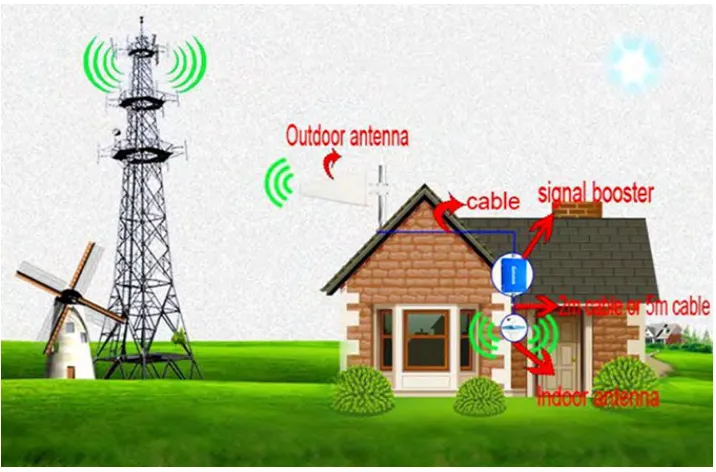
[image:19.595.126.484.338.574.2]must achieve almost impedance bandwidth about 900 MHz. Radiation pattern and radiation efficiency these are one of the significant characteristics that must be taken into account to complete the antenna design. A nearly omni-directional radiation pattern is desirable in that, it can ease in the receiver and transmitter location. This shows maximizing the half power beamwidth and minimizing directivity and gain. Conductor and dielectric losses should be minimized in order to enlarge the radiation efficiency, while the Low loss dielectric used to maximize radiation efficiency. The high radiation efficiency is imperative for GSM antenna because the transmit power spectral density is excessively low. Therefore, any excessive losses happened by the antenna, it could potentially compromise the functionality of the system. The primary application focuses on integrated circuits for portable electronic applications. Therefore, the antenna is required to be physically compact and low profile, preferably planar. In our projects, it has been evaluated and presented several topologies, considering effect between each design.
Figure 2.1: The system topology of GSM
2.2.3 GSM Advantages
8
8
many information about GSM (global system of mobile) which we can gain knowledge from, so we can now tell some of advantages of GSM:
i. A large number of calls can be made from a single tower, as it divides the frequency of the bands into many channels. Due to its features, it is widely accepted and covers 82% of the global market. So, GSM works on the basis of Time division multiple access (TDMA) which allots a specific time period at specific frequency to the GSM.
ii. GSM competes primarily with Code Division Multiple Access technology. Global System for Mobiles is the primary technology used globally for 3G mobile networks, with about a 73 percent market share.
iii. GSM can provide compatibility, multitasking and speed advantages over CDMA on a 3G network.
2.2.4 Disadvantages of GSM
i. GSM can share multiple users with the same bandwidth, with enough users, the transmission can encounter interference. Therefore, 3G have been developed on different types of networks than GSM to overcome this reason. ii. GSM can interfere with certain electronics, such as pace makers and hearing aids, this interference happens due to the fact that GSM uses a pulse-transmission technology.
iii. High gain and large bandwidth.
2.2.5 Spectrum of Frequency
9
9
GSM has the compatibility which is from the speed advantage. In addition, the GSM of microstrip patch antenna consists of a radiating patch on one of side of dielectric substrate which has a ground plane on the other side. For good antenna performance, a thick dielectric substrate has a low dielectric constant which is desirable since this provide better efficiency, better radiation and larger bandwidth. Interference in only part of the spectrum reduces the amount of received signal, but the pulse still can be recovered to restore the signal. Hence GSM is perhaps the most secure means of wireless transmission ever previously available [11].
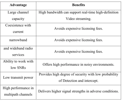
[image:21.595.109.503.359.685.2]Researchers and engineers are working to develop the GSM technology in the near future. With such advantages, the electronics user may able enjoying the technology of GSM and advanced the technology of communication. We can show some advantages and benefits of GSM system.
Table 2.1: The advantages and benefits of GSM
Advantage Benefits
Large channel capacity
High bandwidth can support real-time high-definition Video streaming.
Coexistence with
current Avoids expensive licensing fees. narrowband Avoids expensive licensing fees. and wideband radio
services Avoids expensive licensing fees. Ability to work with
low SNRs Offers high performance in noisy environments. Low transmit power Provides high degree of security with low probability
of Detection and intercept. High performance in
10
10 2.2.6 Global System of Mobile Applications
Fundamentally, from the Shannon-Hartley theorem, the GSM provides high data rates using very low power at very limited range, which will lead to the applications well suited for wireless personal area network (WPAN). These advantages provide GSM to be a circuit-switched system that divides each 200kHz channel into eight 25kHz time-slots. GSM operates in the 900MHz and 1.8GHz bands in Europe and the 1.9GHz and 850MHz bands in the US. The 850MHz band is also used for GSM and 3GSM in Australia, Canada and many South American countries. GSM supports data transfer speeds of up to 9.6 kbit/s, allowing the transmission of basic data services such as SMS (Short Message Service). Another major benefit is its international roaming capability, allowing users to access the same services when travelling abroad as at home [3].
Secondly, GSM technology can be entered in -Digital Communication such GPS, Cell Phones, Laptops. And Mobile Station The mobile station (MS) consists of the mobile equipment (the terminal) and a smart card called the Subscriber Identity Module (SIM). The SIM provides personal mobility, so that the user can have access to subscribed services irrespective of a specific terminal.in addition, High data rate of GSM systems are capable of gathering and disseminating or exchanging a vast quantity of sensory data in a timely manner. The cost of installation and maintenance can drop significantly by using GSM sensor networks due to being free from wires. This advantage is especially attractive in medical applications because GSM sensor network frees the patient from wires and cables when extensive medical monitoring is required. Furthermore, with a wireless solution, the coverage can be expanded more easily and made more reliable [3].
11
11
Lastly, GSM can also be applied to radar and imaging applications. It has been used in military applications to locate enemy objects behind walls and around corners in the battlefield. It has also found value in commercial use, such as rescue work where GSM radar could detect a person's breath beneath rubble, or medical diagnostics where X-ray systems may be less desirable.
[image:23.595.158.454.270.464.2]Due to wide applicable of the GSM systems motivate most of the developers and engineers to improve the systems in near future, by making it useful for the further long distance usage as well. Recently developers such as Motorola and Intel has step into optimizing the usage of GSM technology in our daily life by providing high speed, short-range wireless personal area connectivity for PCs and mobile devices [3].
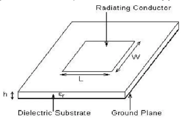
Figure 2.2: A Typical Microstrip Antenna
2.3 Selection of Antenna for GSM Antenna
12
12
performance prediction. Ideally, the dielectric substrate should be low (r 2.5), to enhance the fringe field that account for radiation However, other performance requirements may need to use dielectric constant whose dielectric constant greater than the above mentioned value. Microstrip antennas are characterized by a larger number of physical parameters than are conventional microwave antennas. They can be designed to have many dimensions and shapes.
All microstrip antennas can be divided into four categories: microstrip patch antennas, microstrip dipoles, printed slot antennas, and microstrip traveling wave antennas.
2.4.1 Microstrip Patch Antennas
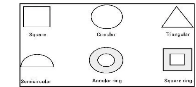
[image:24.595.125.453.565.712.2]A large number of patch microstrip antennas have been studied and used up to date. The rectangular and circular patches are the basic and most commonly used microstrip antennas. These patches can be used for the simplest and the most demanding applications. For instance, characteristics such as dual and circular polarizations, dual frequency operations, frequency agility, broad bandwidth, feed line flexibility, omni-directional pattern and so on are easily to achieve. Moreover, Patch antenna are popular for their well-known attractive features, such as low profile, light weight and compatibility with Microwave Integrated Circuit (MIC) and Monolithic Microwave Integrated Circuit (MMIC). A microstrip patch antenna consists of a conducting patch of any planar or non-planar geometry on one side of a dielectric substrate with a ground plane on other side. Typically a patch antenna has a gain between 5 and 6 dB. Furthermore, as shown in figure the antenna patches can have several shapes, while the most used patches shapes are circular, square and rectangular [11].