Theses
Thesis/Dissertation Collections
5-1-1985
Novel array representation methods in support of a
microcomputer-based APL interpreter
Daniel Fleysher
Follow this and additional works at:
http://scholarworks.rit.edu/theses
This Thesis is brought to you for free and open access by the Thesis/Dissertation Collections at RIT Scholar Works. It has been accepted for inclusion
in Theses by an authorized administrator of RIT Scholar Works. For more information, please contact
Recommended Citation
Novel Array Representation Methods
in Support of a Microcomputer-based APL Interpreter
by
Daniel Fleysher
A thesis, submitted to
The Faculty of The School of Computer Science and Technology,
in partial fulfillment of the requirements for the degree of
Master of Science in Com puter Science
Approved by
:
Guy Johnson
Professor Guy Joh nson
Jim Hammerton
Professor James Hammerton
Jack Hollingsworth
Professor Jack Hollingsworth
Peter G. Anderson
Professor Peter Anderson
Novel Array Representation Methods
in Support of a Microcomputer-based APL Interpreter
by
Daniel Fleysher
Permission to reproduce this thesis in whole or in part is hereby granted to the
Wallace Memorial Library of RIT, unless such reproduction is for commercial use or
profit.
Daniel Fleysher
1.2.
Abstract
Objective:
To
study
novel waysofrepresenting data
arraysfor
potential applicationin
amicrocomputer-based
APL
interpreter. The
goalis
to
find,
for
arrayscontaining
mixedintegers
and realnumbers,
away to
improve
both
storageefficiency
andthruput,
overthat
obtainableusing
conventionalAPL interpreter
array
representations.
Investigation:
For the
purposesofthis study, three
representativeAPL
operators were chosenfor implementation
-dyadic
addition,
multiplication and selection.To
establish a setofbase
casesfrom
whichto
work,
these
three
operators wereimplemented
for
two
distinctly
different data
structures:Case-0:
arrayscontaining
only
fixed
length
floating
pointdata
elementsCase-1
: arrayscontaining
only
fixed
length integer data
elementsThese
two
cases aretermed
"homogeneous"because
alldata
elements within eacharray
share a commondata
structure -the
conventional approach
for
APL
interpreters.
Three
additional "heterogeneous" cases werethen
built
uponthe
homogeneous
base
cases:Case-2:
arrayscontaining
mixedfloating
point andinteger
fixed length
data
elementsCase-3:
arrayscontaining
mixedfloating
point andintegerdata
elements,
withthe
integer
elementshaving
variablelength
Case-4:
arrayscontaining
fixed
length
pointersto
variablelength
Case-3
data
elementsFor
all ofthese cases,
space andtime tradeoffs
werestudied and charted.Exerciser
programswere writtenin
BASIC to
drive
the
5 Case-n
implementations
to
enabledirect
comparison ofthe
5
storageallocationapproaches; these
driver
routines preparedtest
data,
ranthe
addition/multiplication/selectionexercises,
retrievedtime
and spacemeasurements,
and performeddata
reductionfor
presentationin
this
report.The
5
Case-n
implementors
were writtenin 6502 CPU
assembly
language,
and providedthe
functions
ofaddition, multiplication, selection,
timing,
ancfdataformat
conversionbetween BASIC
andCase-n
data
structures.Fixed length
floating
point arithmetic wassupported onthe target
microcomputerfor
which all codewas written -anAtari 800. In
supportofmulti-byteinteger
arithmetic,
however,
original addition and multiplication atomicfunctions
requireddevelopment.
elements.
This
producedastonishingly fast
selectionthruput
for
some applications, anddismally
poor selection performancefor
others.At the
end ofthe
report are suggestionsfor future development
ofthe
variablelength
data
element selection algorithm.Case-4
(pointers
to
heterogeneous
variablelength
data
elements)
wasintroduced
to
enablethe
conventional address calculation selection schemefor
variablelength
elements.The
addition ofthe
pointersdid
nothave
muchimpact
uponthruput, but
the
additional space requiredfor
the
pointerserasedthe
space savings achieved with variablelength
elements.1.3.
Key
Words
and
Phrases
addition,
APL,
array,
data
structure,
floating
point,
heterogeneous, index, integer,
microcomputer, multiplication,
selection1.4.
Computing
Review
Subject Codes
This
thesis
contains material which canbe
categorized under one ofthe
following
three
Subject Code
classifications:D.
Software
D.3
Programming
Languages
D.3.3 Language
Constructs:
Data Types
&
Structures
E. Data
E.2
Data
Storage Representations: Primitive Data Items
G. Mathematics
ofComputing
G.1
Numerical Analysis
1.5.
Table
of
Contents
1.
Prelimary
Information
1.1.
Title
andAcceptance
Page
Frontpiece
1
.2.Abstract
1-2
1
.3.Key
Words
andPhrases
1-3
1.4.
Computing
Review Subject Codes
1-3
1
.5.Table
ofContents
1-4
2. Introduction
andBackground
2-1
2.1
.Problem
Statement
2-1
2.2. Scope
ofInvestigation
2-2
2.3.
Previous
Work
2-4
3.
System Specification
3-1
3.1.
Data Structures
3-2
3.2.
Functions Performed
3-4
3.3. System Flow
3-4
4. Architectural Design
4-1
4.1.
Assembly
Language Implementors
4-1
4.2.
BASIC Language
Driver
4-1
4.3.
Memory Map
4-2
4.4. Hardware Utilized
4-4
4.5. Software
Utilized
4-4
5.
Detail
Designs
5-1
5.1.
Implementor-Driver
Interface
5-1
5.2.
Overview
5-3
5.2.1. Initialization
5-4
5.2.2.
Loop Setup
5-4
5.2.3. Main
Loop
5-7
1.5. Table
of
Contents,
cont'd
5.3. Integer Addition
5-9
5.4. Integer
Multiplication
5-9
5.5.
Selection
5-11
5.6. Elapsed Time
Measurement
5-13
6.
Investigation
6-1
6.1. Integer Function Speed
6-1
6.2. Variable Length Data Elements: Space
Requirements
6-7
6.3. Variable Length Data
Elements: Thruput
6-10
6.4. Type Coercions
6-12
7. Conclusions
7-1
7.1. Thesis Validation
7-1
7.2.
Further
Work
7-2
7.2.1.
Fixing
the Case-3
Defect
7-2
7.2.2. Variable
Length
Floating-point Data Elements
7-3
7.2.3. Integer Multiplication
Lookup
Table Size
7-3
8.
Bibliography
8-1
9.
Appendices
9-1
I
Floating
Point Package
II
Data Tables
III BASIC Program
Listings
2.
Introduction
and
Background
This
sectiondescribes
thepurposeofthis study, thepotentialapplication, theproblemstobe
examined,and past workwhichis
relevant.References
to theliterature
oftheform
[n]
aretobe
found
in Section
8,
theBibliography.
2.1.
Problem Statement
APL
is
a concise and powerfullanguage. Unlike
mostotherhigh level
languages,
it
treatsarithmetic operationsonlarge
arraysofdata
asif
thearrays were atomicentities. Theconstructionofloops for
repetitively performing
anoperationupon all theelementsof anarray is
actually hiddenfrom
the user; as aconsequence,theloops
canbe
canbe built very
efficiently,executing
withsuchlow
overheadastoapproachtheperformanceofmachinelanguage implementations.
APL
is
alsotypically
implemented
asaninterpreted language. This
providestheutmostin
flexibility
and userfriendliness;
it isquite
commonfor
userstobuild
anddebug
functions in
aninteractive
style,greatly reducing
theamountofplanning necessary before coding
canbegin.
Thus,
APLis
perfectly
suitedtoquickdevelopment
of smalltomedium size"data-crunching"
application programswitha minimum ofprogrammereffort.
Data-intensive business
andscientific applications aregradually making
thetransitionfrom
the mainframeto thepersonal microcomputer.Micros
are alsobecoming
requiredtosupporthigh
speed real-timeanimation ofhigh
resolutionimages.
Theseapplicationsrequireboth high
speed calculation and movement ofrelatively large
arraysofdata.
APLis
thusa potential candidatefor
suchapplications, providedanAPLinterpreter for
the targetmicrocomputeris
available.Traditional APL
interpreters
adjusttheinternal
representation ofdata
elementstooptimize storage utilizationandprocessing
thruput[14].
For example,smallintegers
canbe
storedinless
spacethanfloating
pointrealnumbers. In addition,integer
representations canbe
processedfaster
thanfloating
pointforms.
Thisis especially
truefor
microcomputers,wherefloating
point calculations areinvariably
performedby
software(rather
thancostly
specializedhardware).
In summary,by
optimizing
internal representationfor
thedata
being
represented,both
storage space andprocessing
timecanbe
saved.This
is important
onamicrocomputer,whereboth
space and processor powerarecritically
shortresources.Traditional APL
interpreters
invariably
assigna singlerepresentationfor
all elementsof anAPLarray
atthetimeofcreation(or
re-creation)[14].
Thus,
alldata
elementsof anarray
areforced
into
the samerepresentation which violates ourdesire
to tailorrepresentationtodata. Of
course,representing
alldata
elementssimilarly
simplifiestheloops
thatAPLmustconstruct and executeto performiterative
arithmetic,asonly
one arithmetic routinetailoredtoa specificdata
representation needbe
called.Moreover,
fixed-size
elements enable random accesstoarray
components(such
as rows, columns,orindexed
specificelements),because
theiraddresses canbe
calculateddirectly
using
theknown
elementsize. Randomaccessinto
anarrayofvariable-sizeelementswouldrequiresequentially
steppingthrough thearrayfrom
thebeginning,
unlessthearray is
supplementedwith some sort ofindex
table(cf.
"beating"and
"slack
representation",section2.3.).For example,aparticular
array
containingmostly integers
andsprinkledwith afew
sparsely
scattered real elements,will
have
all elementsrepresentedinternally
in
floating
pointform;
wesay
thearray
elementshave
a"homogeneous"
(fixed
size andtype)
representation.From
theviewpointThe
subject ofthis thesisis
tostudy
alternativestohomogeneous
arrays,for
potential incorporationinto
amicrocomputer-basedAPLinterpreter.
Specifically,
variablelength integers
andfloating
point representationswillbe
mixedwithinthesamearray,making it
"heterogeneous"
Thetradeoffs associatedwith
building
andprocessing
suchheterogeneous
arrayswillbe
explored. Problemssuch astheeffect ofvarying
elementtypeuponloop
executionoverhead, and randomly accessing variablelength
data
elementswillbe
dealt
with. Theoverall goalis
todetermine
whetherheterogeneous
representationscansimultaneously improve
storageutilizationand processing thruputovertraditionalhomogeneous
representations,despite
theproblemsthatheterogeneous representationsintroduce.
2.2. Scope
of
Investigation
This
thesisstudiesfive
different internal
representationsfor
APLarrays:No. Name
Array
typeElement
Representation ElementSize
0
F.P.base
homogeneous
fixed
(floating
point)1 Integer
base
homogeneous
fixed
(integer)
fixed (6
bytes)
fixed (6
bytes)
2 Fixed Length
heterogeneous
mixed(floating
point/integer)
fi
xed(6
bytes)
3
Var. Lengthheterogeneous
mixed(floating
point/integer)
variable(1-6
bytes)
Pointer
heterogeneous
pointertomixed
(floating
point/integer)
fixed
pointer(2
bytes)
tovariable
(0-6
bytes)
The
homogeneous
floating
pointandinteger
representationsarebase
cases,and are numbered "0" and"1"
in
theabovetable. Forboth
cases, theelementlengths
arefixed
at6
bytes,
anddatatypes
ofallelements arethesamethroughoutthearray. Thehomogeneous
cases(0
&1)
are referenced as"floating
pointbase
case"
and
"integer base
case"
respectively in
thisreport.Three heterogeneous
representations arebuilt
uponthehomogeneous
cases. In theheterogeneous
cases,both integer
andfloating
point elements existwithin agivenarray,depending
uponthedata
being
represented. InCase-2,
the"heterogeneous
fixed length
case",both integer
andfloating
pointelementlengths
arefixed
at6 bytes.
Althoughno spaceis
savedwiththisrepresentation,
integer
elementscanbe
processedby
faster
(integer)
functions
than theirfloating
pointneighbors.Of
course, the discriminationoffloating
point vs.integer
elementsandtheselection oftheappropriate
processing
routineintroduce
undesirableoverhead.Case-3
is
namedthe"heterogeneous
variablelength
case"
This
caseis built
uponCase-2,
but
introduces
variablelength
for
theinteger
elements.Floating
pointelementsremain6
bytes
in
length. The
objective ofthisrepresentationis
tosavestorage space whilesimultaneously
deriving
thebenefits
ofinteger
processing.However,
thefact
thatelementlengths
vary
withinanarray
impacts
theability
to randomlyaccess agivenelement.Finally,
Case-4introduces
fixed length
pointersto thevariablelength
elementsofCase-3. Case-4 is
thusreferredtoasthe"heterogeneous
pointercase"
Theobjective ofthisrepresentation
is
to regainthesimplerandom accessaddressabilityoffixed length elements,
whileAlthough
thesemay be
thoughtof ashomogeneous
arraysconsisting
ofpurely fixed-length
pointers, thedata
elementspointedtoareheterogeneous.
To actually
testprocessing
thruputfor
these5waysofrepresenting
APL arrays,threerepresentativedyadic
(two-argument)
APLprimitiveoperationsareimplemented: array
addition, arraymultiplication,
andarray
selection.These
operations arechosenbecause
they
arefundamental
toallAPLprocessing.
Addition
providesa goodfast baseline
toexploretherelativespeed advantagesofhandling
arrays of various representations. Multiplicationis
chosenbecause
ofthesignificant numericalprocessing load it
presentstoaCPU
withoutthebenefit
ofhardware
assist.Finally,
selection
is
chosenbecause varying
thedata
element sizetominimize spacerequirementsdestroys
therandomaccessibility
thatwas possiblewithfixed
sizeelements,andforces
serial access.Thus
theselection algorithm must
be radically
modifiedin
ordertosupportvariablelength
elements,whichis
bound
toaffectprocessing
thruput.Addition,
multiplication and selection areimplemented for
eachofthe5array
representationcases.This
supportsthe threeprimary
areasofinvestigation
undertakenin
thisthesis:1)
Faster IntegerFunctions
-Canaddition,multiplication and selection
really be
madesignificantly faster
by introducing
integer
representationsfor integer data
elements andusing integer functions
toprocessthem,
instead
ofalwaysusingfloating
point representations andfloating
pointfunctions?
Thebenchmark
for
comparisonis
acommercialfloating
point software packagedeveloped
by
Atari,
Inc.which
is included
withthebuilt-in operating
system codeofevery
Atari Home Computer.The
workdescribed in
section6.1investigates
thisquestion.2)
Variable Length Data ElementsCan
heterogeneous
arraysbe built successfully
usingmixturesof variablelength integer
andfloating
point elementstoreduceoverall spacerequirements?Does
thespace overhead oflength
flags
and codetointerpret
themconsumethespace savingsthatwouldhave
resulted? Doestheprocessing
overheadintroduced
by
variablelength
elementsnegatively
affectthruput?Since
theconventionalprocessof selectioninvolves
thecalculation ofanelement's addressfrom
its
(fixed)
size andindex,
variablelength
elementsrequireanew algorithmtosearchfor
thedesired
elements,astheirsizeis
nolongerknown
or constant. Does thisdestroy
thruputfor
theselection
function? Could fixed length
pointerstovariablelength data
elements permitthere-introduction
ofstraight calculationofelement addresses? Withwhatbenefit,
and at what cost?Thespace savingspotentialof variable
length
data
elementsis discussed in
section6.2.
Processing
thruputimpacts
of variablelength
arrays wasinvestigated in
theworkdescribed
in
section6.3.
3)
Type Coercions: ImpactuponThruputWhenaddition or multiplication
functions
encountera pair ofelementstobe
processedwhichhave dissimilar
representations(e.g.,
floating
pointvs.integer),
willthe timerequiredtoconvert2.3. Previous Work
From
its early
beginnings
in
thelate
1960's,
theactualimplementation
ofAPL Interpretershas
remainedmostly
withinthecontrol ofcommercialcompanies. IBM Corporation's Research Divisiondid
virtually
all oftheworkin
thelate
1960's,
tobe joined in
the1970's
by
LP.Sharp
AssociatesofCanada [5].
Understandably,
papers publishedby
theseand otherimplementers
areusuallysketchy
onimplementation
details.
Asearch ofthe
literature for
topicsrelatedto this thesiswasinitiated
attheproposalstage.Only
currentProceedings
ofACM APLConferences
werefound
tocontain articlesrelevantto thelow-level design
orientation ofthisthesis. TheBibliography
(section
8)
liststhose
papers[9,
10,
11, 12, 14]
dealing
withimplementation innovations designed
tospeedupor extendAPLinterpreters.
References
[9]
and[1
1]
aretypicalofthosepaperswhichdiscuss
speedimprovements.
Reference[9]
discusses
several methodsfor
smart evaluationofAPLexpressions.One
suchmethod,"Beating",
appears applicabletoanAPLinterpreter implemented
onamicrocomputer:data descriptors
areintroduced
whichpoint at elementsoftheactual array. APLfunctions
suchasreshape,take,
drop
andselectionneedonly
manipulatethedata descriptors
toachievetheirresult-thedata itself
need neverbe
moved.Reference
[11]
discusses
several approachestowardmaking
APLcompilation or partial compilationfeasible.
For example, tentativebinding
ofarithmeticroutinesinto
loop
code eliminateshaving
toselecttheappropriateroutinefor
thearray
element(s) tobe
processedon eachiteration
oftheloop.
For example,if
theelementsareknown
tobe integer
(as
opposedtofloating
point),aninteger-optimized function
couldbe
assignedtodo
thearithmeticprocessing
withintheloop.
Suchan approach utilizesthefact
thatarrays arehomogeneous;
a checkwouldhave
tobe
made ateachloop
iteration
to verify that thecorrectroutinehad been
selected,if
therewas a chancethatdata
elementrepresentationcouldchange withinthearraysbeing
processed.Reference
[14]
is
anexampleofapaperproposing
a methodofimplementing
arecently
proposed APLextension called"enclosed
arrays"
This
paperis
of particularinterest because it
containsin
thefirst few
paragraphsan overview ofhow array
elementrepresentations are selectedin those"traditional"
APLsystemsuniversallyreferencedand
rarely described in
theliterature. Reference
[14]
is
alsointeresting
because it introduces
conglomeratearray
elementswhichcanvary in
size within an array,aswouldmy heterogeneous array
elements. Inordertoenable quick addresscalculation
for
selectionandindexing
functions,
theauthorintroduces
"slackrepresentation"-i.e.,
fixed
sizereferencepointerstotheactual variablesizearray
elements,whichlend
themselves tobeating
asdescribed
above.My
searchthroughtheliterature
attheproposalstage uncovered no other papersbearing
onheterogeneous array implementation.
References
[8]
and[13]
aredescriptions
ofoneworking
microcomputer-basedAPLinterpreter.
This
interpreter
is designed
toexecute onan8080-class
microprocessor.During
theproposal phase ofthethesis,
aninformal study
ofthisAPLinterpreter
wasperformedusing
aXeroxmodel820
3. System Specification
This
sectiondescribes
in
moredetail
theprogramsimplemented in
supportofthis thesis. Theoperationsofaddition,multiplication and selection
implemented here
are morefully
specifiedin
thefollowing
paragraphs.Section 3.1
specifiesthedata
structures employedin
implementing
homogeneous
andheterogeneous
arrays.Section
3.2describes
thespecificfunctions implemented
tocreate and processthose
data
structures,and section3.3
specifiestheflow
ofdata
andcontrolbetween
thefunctions
implemented.
For
dyadic
APLaddition andmultiplication, the twoarrays musthave
eitheridentical
shapeor elseone must
be
a scalar.The
additionormultiplicationis
performed,elementby
element,producing
aresultant array. Theshapeofthe resultant
is
thatofthetwoargumentarrays(or
thatofthearray
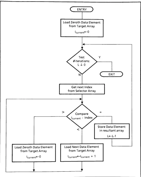
if theother argument was a scalar).InAPL selection, a
"target"
array
containsdata
elementswhichare selectedby
integerindices
containedin
a second"selector"
array. Theresultantarraycontains
data
elements selectedfrom
the target array,witha shapeconforming
tothatoftheselectorarray. In APL notation,theindex
of eachdesired
elementis
expressedin
theselectorarrayasann-tuplecontaining
theposition within eachdimension. The
simpledata
structuresdescribed below do
not supportn-tuples.Therefore,
for
thepurposes ofthis study,theelementsoftheselectorarray
willbe
simple positional referencesto the(linearized)
data
elementsofthe targetarray. Theconversion ofn-tupleindex
representation whichwouldbe
found in
realAPLprogramsinto
thesimplepositional representation usedhere is
a simplecalculationinvolving
thelength
of eachdimension
ofthe targetarray. Itis
awell-understood algorithm,andis
considered outsidethescopeofthisimplementation.
A
few
more commentsconcerning
system specificationshouldbe
statedhere.
In general,for
eachhomogeneous
andheterogeneous
casebeing
studied, theaddition, multiplicationandselection routines arecapable ofhandling
allinput
argument representationslegal for
thatcase. Forallheterogeneous
cases,theadditionand multiplicationroutines calculatenotonly
thevalue of eachresultant
array
element,but
alsotheoptimal representationfor
it,
withintheconfines ofthecasebeing
studied. For example,in
thevariablelength
case(Case-3)
if
twofloating
point elementsareaddedto producea resultelementwhich
is best
representedas a2-byte
integer,
then thatelementwill
be
stored assuch withintheresultant array.The
heterogeneous
pointercase(Case-4)
arrayscontainboth data
elements and pointersto them. Pointerscanreferencedata
elementswhicharenotnecessarily in
thevectorofdata
elements associatedwiththepointers. Thatis,
thiscaseis
optimizedfor
commondata
values(the
identity
elements"0"
for
addition,"
1"
for
multiplication):These
constantsarestoredin
thepointer case(Case-4)
implementationcode. Anarray
might containpointersreferencing
these(common)
valuesby
pointing
to themin
theimplementor
code. Thusnocorresponding data
elementcomponents wouldbe
requiredin
thearray itself. This has
thepotentialfor saving
thestorage spacethatwouldbe
requiredfor duplicate
common values.Pointers
could alsobe
used asin
reference[14]
"slackrepresentation" tosavethe
copying
ofdata
elements
from
an argumentarray
to theresultant array. Suchdata
elements couldthenhave
more thanone pointerelementreferencingthem,
soan actualAPLinterpreter
would require eachdata
elementtocarry
ausage counterbyte
or some othermeansofnotifying
garbage collection routines whenadata
element'sstoragecouldbe freed. Since
garbage collectionis
beyond
thescopeofthis study,counterbytes
are omittedfrom
thepointercaseimplementation,
andalldata
elementsnot equalto"0"or" 1"
3.1. Data Structures
Regardless
ofwhichcaseis
being implemented,
all arrayshave
thesameoverall structure. Eachhas
aheader
whichcontains shapeinformation,
followed
by
adata
areawhichcontains alinearized
vectorofthe
data
elementsthemselves:Header
Data Area
Thestructure ofthe
header is depicted below.
Thefirst byte
containstherank ofthearray
- thatis,
thenumber ofdimensions.
Thedimension length
specificationsfollow
therankbyte.
Eachdimension length is 2 bytes long.
#dims
"n"(rank)
length
ofdimension
#1length
ofdimension
#nByte 1
Bytes
2& 3
Bytes(2n)&(2n
+1)
Thus
aheader
for
a scalardata
elementwould containonly
a singlezerobyte,
whiletheheader
for
a 127-dimensionarray
would contain aleading
byte
withthevalue of127,
followed
by
127pairsofbytes,
eachcontaining
thelength
oftheappropriatedimension.
Avalue of zerofor
anydimension
length
resultsin
APL's"empty
vector"
The
data
area whichfollows
theheadercontains a series ofdata
elements arrangedin
row-major order(APL
standard). The number ofdata
elementsin
thedata
areais
preciselytheproduct ofthedimension
lengths in
theheader
(except for
ascalar,whichhas
onedata
elementinthedata
area).data
element #1
data
element#2
data
element#dim-|
dim2
...dimn
Anexception
is
thedata
arraystructurefor
thepointercase(Case-4),
whichis divided into
twoareas
-avector of
fixed
pointers,and avectorofdata
elementswhichthey
(in
general)pointto.Header Pointers Data Elements
Thestructureofthe
data
elementsis
what variesfrom
casetocase.This
structureis
illustrated
for
eachcase
in Figure
3-1.Case-0:
F.P
base
case
Case-1
:Int.
base
case
Case-2:
Fixed
Leng.caseCase-3:
Var. Leng. case
Case-4:
Pointer case
+ expon't
I
m
1
a n
1
t
i
s s a1
1
1
+
dummy
1
1
v a
1
1
u e1
1
1
+ expon't
/flag
1
m a n t i
1
s s a
1
or v a 1
1
1
u e
1
+ expon't
/flag
m a n t i s s a or v a1
u eI
pointer;
+ expon't:
[image:14.530.34.503.89.468.2]/flag
:
m a n ti
s s a or v a u e;
Figure 3-1
.Structure
ofIndividual Data Elements
The
heterogeneous fixed length
case(Case-2)has
arrayswithelementsoffixed
size,but
oftwodifferent
(mixed)
representations. Theleading
byte
(used for
theexponentin
floating
pointrepresentations)
flags
aninteger
representationby having
thevaluezero,anillegal
exponentvalue.(See
Appendix Ifor
acompletediscussion
ofthefloating
point package andthelegal
rangeofexponentvalues.)
The
heterogeneousvariablelengthcase(Case-3)
extendsCase-2
by
introducing
variable sizeintegers.
Leading
byte
values of2through6
indicateaninteger data
element oflength
2 through6
bytes
(containing
a 1 through5byte
value,respectively). Thespecialvalueof0 for
theleading
byte
indicates
adata
element valueofzero,and 1indicates
avalueofone:thesespecialcasesareone-byte
representations. Becausethelead byte for
floating
point representationis
fully
occupiedby
the exponent, thereis
noroomfor
abyte
counterandfloating
pointdata
elementlength
remainsfixed
at
6 bytes.
actual
array data.
InaCase-4 array, theset offixed
size pointersimmediately
follows
thearray
header bytes
whichdefine
thelength
ofeachdimension.
Inturn,
thesepointersarefollowed in
generalby
thevariable sizedata
elementstowhichthey
point.However,
pointerstocommon values(0
and1)
can reference such valuesin
the code,as mentioned abovein
section3.1. Insucha case thereis
nodata
elementcorresponding
to the pointer,resulting in
a spacesavings.3.2.
Functions Performed
Foreach ofthe
five
cases ofarray
elementsdescribed
above,asetofthreeassembly language
routines are writtentoprovidethe threeprimitiveAPL operations, addition,multiplicationand selection. Each routinetakesas argumentsthestart addresses oftwooperand arrays andthestart addressofthearea reservedfor
theresultantarray. Inadditiontoleaving
theresultantarray in
thedesignated
area,eachroutine makes availabletoits
callera measurementof actual executiontime andarray
size.This
and otherdata
communicationsoccur via aninterface
table. Theinterfaces
to theassembly language
routinesfor
eachofthefive
cases areidentical,
sothatthey
canbe
calledfrom
acommondriver
program.The
driver
programis
writtenin BASIC. Itprovidesaflexible
testenvironmentandinterface
for
theuser. Itgeneratestest
data,
runsthedesired assembly language
routinestoprocessthedata,
retrievesanddisplays
theresults,and calculatesandstores statistics such as storageefficiency
and mean executiontime.The BASIC
interpreter
onwhichthedriver
program runsdeals exclusively
in 6-bytefloating
point numerical representation.Thus,
auxiliary assembly language
routinesareneededtoconvertback
andforth between BASIC'S
straightfloating
pointrepresentationandthemoresophisticatedarray representationsutilizedin
thefive
cases. Conversionis
providedin both directions between
twoBASIC
arrays(one containing
testdata
and theothercontaining
shapeinformation)
and aCase-n
array
incorporating
both.
Floating
pointto/frominteger
element conversionis
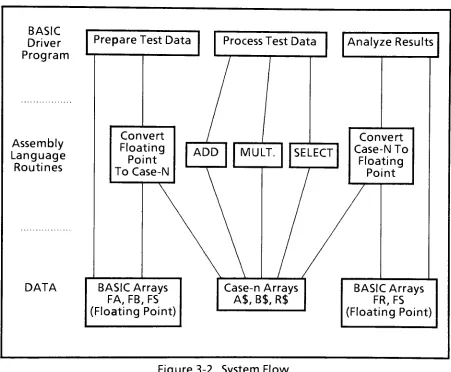
also provided.3.3. System Flow
The
following
chartlists
all ofthe assemblylanguage
routineswrittenfor
each ofthefive
cases:Routine
Arguments(addresses
of:) Return ValueSide Effects
Arithmetic:
ADD
MULT
SELECT
2argument& 1 resultantCase-narrays
2
argument& 1 resultantCase-narrays2argument
&
1 resultantCase-narrayserrorcode
errorcode
errorcode
executiontime
executiontime
executiontime
Conversion:
FLTTOCn 1 BASIC
data,
1 BASICrankinput
arrays,and errorcode 1 Case-nresultantarray
CnTOFLT 1 Case-n
input
array,and error code1 BASIC
data &
1 BASICrank resultantarray
executiontime
The
aboveroutinesoperateonthefollowing
storagearrays,defined
and reservedby
the BASICdriver
program:BASIC-compatible
floating
pointdata
arrays:FA,
FB&
FRBASIC-compatible
floating
point rankspecificationarray:FS
Space
reservedfor Case-n
arrays:A$,
B$ &
R$
BASIC
Driver
Program
Prepare
Test Data
Assembly
Language
Routines
DATA
Process Test
Data
Convert
Floating
Point
To Case
ADD
MULT.
Analyze Results
SELECT
Convert
Case-N
To
Floating
Point
BASIC Arrays
FA,
FB,
FS
(Floating
Point)
Case-n Arrays
A$,
B$,
R$
[image:16.530.46.497.172.544.2]BASIC
Arrays
FR,
FS
(Floating
Point)
Figure 3-2. System Flow
Figure 3-2
diagrams
theflow
ofcontrolduring
exercising
oftheassembly language
routines.First,
theBASIC driver
program preparestestdata in
arraysFA &FB,
places shapeinformation in array
FS,
and callsFLTTOCn toproduceCase-ncompatibletestdata in
storage areasA$
&B$,
respectively.Next,
thedesired
arithmeticroutineis
called,whichprocessesthearraysin
A$
andB$,
leaving
the resultantarray in
R$.Finally,
theresultant canbe
madeBASIC-compatible for evaluation,
by
calling
CnTOFLT
whichleaves
theshape oftheresultin array
FSandthedata
resultin array FR.
values
between
theBASIC driver
program andtheimplementor
module.Among
otherthings,
this tableprovidestheaddressesoftheassembly language implementor
routines, theelapsedtimetaken toprocessthedata
by
animplementor function
andthesizeoftheresultant array.This
tableis
4. Architectural
Design
The
following
sectionsdescribe
theoveralldesign
ofthesoftwareimplemented
in
support ofthisthesis,
andtheenvironmentin
whichit
operates.4.1.
Assembly
Language Routines
Thesoftware
designed
toimplement
thethreeAPLfunctions
understudy
waswrittenin 6502
Assembly
Language
on anAtari800
home
computer. Foreach case ofdata
representation,a separate stand-alone moduleimplements
addition,multiplication and selection.Since
thereare5 suchcases, thereare5
independent (although
related)"implementor"
modules. Inadditionto the threearithmetic
functions,
each module contains utilitiesfor measuring
elapsedtimeandfor
converting data
representationsback
andforth between
aninternal form
specificto thecasebeing
studied,and an externalform
compatiblewithAtariBASIC
(see
following
section). Theaddresses of allfunctions,
utilitiesanddata
pointers areheld in
atableatthebeginning
of eachimplementor
module.A
driver
programfor exercising
thismodule caninterface
withit
viathistableof pointers.Since
the tablesin
allimplementor
moduleshave
thesameformat
andmemory
location,
thedriver
programdoes
not needtoknow
whichcaseofdata
representationis
being
exercised. Animplementor
module canbe
replacedin memory
by
overlaying it
with another(from
disk),
andthe same exercise canthusbe
performedfor different
casesofdata
representation,allowing easy
comparison of results.Also
writtenin
Assembly
Language
is
autilitywhichcallsanimplementor
modulein
from disk
andloads it into
theassignedmemory
area,overlaying
theprevious contents.4.2. BASIC Language
Driver Program
Asingle
driver
program waswrittentoexercisetheimplementor
modulesdescribed
above.This
program preparestestdata,
exercisesthecurrently loaded implementor
module,and printsor evaluatestheresults.The Basic driver
programcontains adata
declarationheader
whichexactly
matchestheformat
oftheinterface
tabledefined in
theAssembly
Languagecode. Alsodefined is
theaddress ofthe utilityusedfor
loading
animplementor
moduleinto memory from disk. This
gives theBasic
programtheability
to"swap
in"thevariousimplementor
modules.There
is
a "hole"built
into
the Basicdriver
program whereany
ofseveral exercisersubprograms canbe inserted.
Thesearealsowrittenin
BASIC,
andbecome
part ofthedriver
program. Eachexerciser subprogram containsaparticularseries ofBASICstatementsfor creating
testdata,
calling
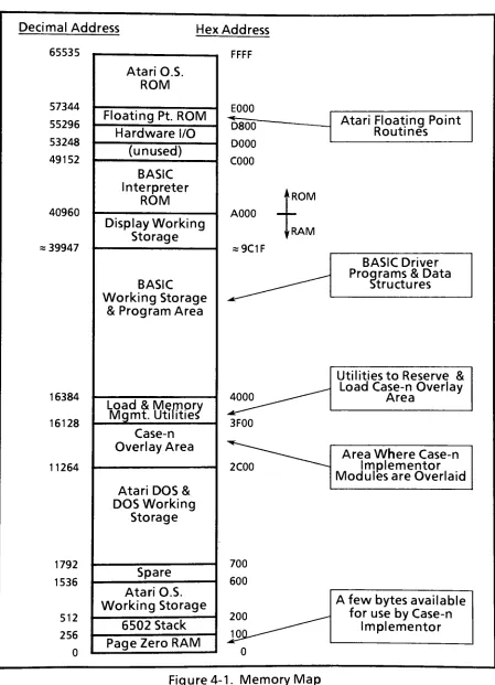
4.3.
Memory
Map
Figure
4-1showsthememory map
oftheAtari800
home
computer.Each block in
thememory map
is described
below.
Page Zero RAM
-special
6502
instructions
are available whichaccesstheseaddresses. PageZero
accesses arefaster
thanothermemory
accesses,andindirect
pointerscanonly
residein
Page Zero.The
AtariO.S.
andBASIC
interpreter
reserve most ofPage
Zero,
but
afew locations
are availablefor
applicationssuch asthisproject.6502 Stack
- the6502
usesthisarea
for saving
return addresses and processorstatuses.Temporary
data
can alsobe
saved onthestack.Atari
O.S.
Working
Storage
-memory
usedby
theoperating
systemfor
flags, buffers,
etc.Spare
-thisareais
availablefor
useby
applicationprograms,but
was not usedfor
thisproject.Atari
DOS & DOS
Working
Storage
-memoryused
by
thedisk operating
systemfor its
code,flags,
buffers,
etc.Case-n
Overlay
Area
-each
implementor
moduleis
assembledtostartatthebeginning
ofthisarea.One implementor
moduleis
resident at atime.The
spaceis
usedfor
code,flags
andbuffers.
Load &
Memory
Mgmt.Utilities-two
utilities writtenin
Assembly
Language occupy
thisarea.They
are readin
from disk
atdisk boot-uptime. One
ofthemreservesthe Case-nOverlay
areaand runsatdisk boot-uptime. The
otherutility loads any
ofthe 5implementor
modulesinto
the Case-nOverlay
Area,
andis
callablefrom
BASIC
underoperator orprogramcontrol.BASIC
Working
Storage &
ProgramArea
- thisarea containstheBASIC
driver
program and overlaid exerciser modulewhichpreparesdata
toexerciseimplementor
modules,callstheimplementor
modulesinto
memory,exercisesthem,
retrievesthe results,and prints or evaluatestheresults.Also
present arebuffers
for
thepreparation oftestdata.
Display Working
Storage
- thisarea containsthe
display
buffer
anddisplay
list
(a
display
hardware
control program).It
is
managedby
the Atari O.S.BASIC
Interpreter ROM- theplug-inBASICinterpreter
ROMoccupiesthisblock
ofmemory
addresses.Unused
-not occupied
by
any
memory
ordevices;
for
future
expansion.Hardware I/O
- memory-mappeddevice
addresses,for controlling
theoperation ofthedisplay
hardware,
game controllerports,etc.Floating
PointROM
- thisblock
of
memory
addressesis
occupiedby
theinternal
Atarifloating
point routines.These
areutilizedby
BASIC,
and alsoby
implementor
module codewhenfloating
point operations are required.Atari O.S.
ROM-thecode ofthe Atari operatingsystem residesin ROMs
whichoccupy
thisblock
of memory.This
codeimplements
byte-leveland record-levelI/O functions
to/fromthedisplay,
Decimal
Address
65535
Hex Address
57344
55296
53248
49152
40960
=
39947
16384
16128
11264
1792
1536
512
256
0
Atari O.S.
ROM
Floating
Pt. ROM
Hardware
I/O
(unused)
BASIC
Interpreter
ROM
Display Working
Storage
BASIC
Working
Storage
& Program
Area
Load &
Memory
Mgmt.
Utilities
Case-n
Overlay
Area
Atari
DOS
&
DOS
Working
Storage
Spare
Atari
O.S.
Working
Storage
6502 Stack
Page Zero RAM
FFFF
E000
^D80T
D000
C000
A000
=
9C1F
Atari
Floating
Point
Routines
"ROM
rRAM
BASIC
Driver
Programs &
Data
Structures
Utilities to
Reserve &
Load
Case-n
Overlay
Area
2C00
Area
Where
Case-n
Implementor
Modules
areOverlaid
700
600
A
few bytes
available
for
useby
Case-n
[image:20.530.45.494.71.692.2]Implementor
4.4.
Hardware Utilized
Atari 800 Home
Computer,
with48K
bytes
ofRAMandatotalof26K
bytes
ofROMs
Percom
RFD-40
5i"double
density floppy
Disk Drive
Atari
410
programTape Recorder (for
back-up)
Centronics 739 Printer (for local
listings)
Multi-Tech FM-30
modem(for
remotelistings)
Atari
850 Interface Module
RCAXL-100
19"televisionset
(monitor)
4.5.
Software
Utilized
Atari
BASIC
ROMcartridge-providesflexible
easily
programmeddriver/test
environmentAtari
Assembler/Editor
ROMcartridge-providesCase-n
implementor development
environment5.
Detail
Designs
This
sectionconcentratesuponthedesign
oftheimplementor
modules,asthesearethebasis
ofthis thesis.First
thedetail design
ofthe table thatprovides communicationsbetween
theBASIC driver program andtheimplementor
moduleis
described.
Then
thedesign
ofthe implementormodulesis
outlined,
followed
by
design details behind
important
sections ofthecode. Complete implementor moduleAssembly
language
sourcelistings for
Case-0,
-1,-2,-3and-4appearin
Appendix Mil.5.1
Implementor-
Driver Interface
The
interface
whichprovidescommunicationbetween
the BASICdriver
programandtheCase-nimplementor
being
exercisedis
atableofaddressesanddata
registers,whose structureand memorylocation is defined in both
worlds.The BASIC
driver
program containsthevariabledeclarations
listed in
theleft
column ofFigure
5-1. TheequivalentAssembly
Languagestatementsshownin
the right column are part ofthefile
DEFS.ASM,
whichis included in every implementor
-seethelistings
ofAppendix INI.Excerpt
from BASIC
Driver Program Excerptfrom
Assy. Language DEFS. ASM17 REM ***************************** 0520 *= $2C00 ;T0P OF OSS DOS, 11264 DECIMAL 18 REM *DEFS OF ASSY CODE REGISTERS*
0530 ;C0MM0N POINTERS AND REGISTERS 19 REM ***************************** 0540
; FOR COMMUNICATION WITH BASIC
0560 ; POINTERS TO ROUTINES CALLED FROM BASIC
0570 ; DECIMAL ADDRESS
20 LET AFLTTOCASE=11264:REM HEX $2C00 0580 AFLTTOCASE .WORD FLTTOCASE , 11264 22 LET ACASET0FLT=AFLTT0CASE+2 0590 ACASETOFLT .WORD CASETOFLT 11266
24 LET AADD=ACASETOFLT+2 0600 AADD .WORD ADD 11268
26 LET AMULT=AADD+2 0610 AMULT .WORD MULT 11270
28 LET ASELECT=AMULT+2 0620 ASELECT .WORD SELECT 11272
0640 ; FLOATING AND CASE-N BUFFER POINTERS 0650 PTRBASE
32 LET FLTA=ASELECT+2 0660 FLTA .WORD 0 11274
34 LET AADR=FLTA+2 0670 AADR .WORD 0 11276
36 LET FLTB=AADR+2 0680 FLTB .WORD 0 11278
38 LET BADR=FLTB+2 0690 BADR .WORD 0 11280
40 LET FLTR=BADR+2 0700 FLTR .WORD 0 11282
42 LET RADR=FLTR+2 0710 RADR .WORD 0 11284
44 LET DADR=RADR+2 0720 DADR .WORD 0 11286
0730 ;MISC. STORAGE REGISTERS
46 LET LC0UNT=DADR+2 0740 LCOUNT .WORD 0 11288
48 LET TIMER=LCOUNT+2 0750 TIMER .BYTE 0,0,0 11290
50 LET VCOUNTER=TIMER+3 0760 VCOUNTER .BYTE 0 11293
52 LET TMPCTR1=VC0UNTER+1 0770 TMPCTR1 .BYTE 0 11294
54 LET TMPCTR2=TMPCTR1+1 0780 TMPCTR2 .BYTE 0 11295
56 LET DELTAA=TMPCTR2+1 0790 DELTAA .BYTE 0 ,11296
58 LET DELTAB=DELTAA+1 0800 DELTAB .BYTE 0 ;11297
60 LET DELTAR=DELTAB+1 0810 DELTAR .BYTE 0 ;11298
62 LET DELTAD=DELTAR+1 0820 DELTAD .BYTE 0 ;11299
64 LET INHIBDMA=DELTAD+1 0830 INHIBDMA .BYTE 0 ;11300 66 LET SCALASW=INHIB0MA+1 0840 SCALASW .BYTE 7 ;11301
68 LET SCALBSW=SCALASW+1 0850 SCALBSW .BYTE 7 ;11302
Figure 5-1
.Implementor
The
first five
entriesin
theInterface
tablearetheaddresses ofthefive
entry
pointstoeachimplementor.
The Assembler
fills
in
these tablevalues.When
animplementor is loaded
theaddresses,which
vary from
implementor
toimplementor,
are availableto thecalling
BASICprogramin
fixed
memory locations.
TheBASIC
command "PEEK"is
usedtoreadtheaddressesoftheentry
points out ofthe
fixed
tablelocations,
sothat thecorresponding
routinescanbe
calleddirectly
with theBASIC
command "USR"The
remainder oftheinterface
tableentries are registerscontaining
strategiccontroldata
withintheimplementor
module.They
areincluded in
theinterface
table toprovidestatisticalfeedback
to theBASIC
driver
programfollowing
theexecution oftheselectedimplementor function.
Accessto these strategic registersalsofacilitates
someimplementor
moduledebug
from
the BASICenvironment.The
rest ofthissectiondescribes
theuseofeach register.Section 3
discusses
thememory-residentdata
arrayswhichsupporttheexercising
of an implementormodule.
These
arrays are reservedby
theBASIC
driver
program. Theiraddresses arepassedin
the "USR"callto the
implementor
routines,whichstoretheminto interface
registersFLTA, AADR, FLTB,
BADR,
FLTR,
and/orRADRdefined in Figure
5-1.These
registers are advancedduring
implementorexecutiontopointto the
array data
elements asthey
arebeing
processed.Following
execution,theregisters
may be
readfrom BASIC
todetermine how
much of anarray
was processed. DADRis
a special pointer usedfor Case-4
topointto thedata
elementregionof apointercase(Case-4)
array.Moving
down
theinterface
tabledefinitions,
LCOUNTis
thestorageregisterfor
theloop
iteration
counter,which
decrements
tozero asthearray
elementsare processed.TIMER
is
athree-byteregister whichreturnstheelapsedexecutiontimewitha resolutionofroughly
a60th
of a second.VCOUNTERisa
one-byteregister whichextendsthisresolutiontoabout1millisecond.
Timing
facilities
arediscussed further in
section5.6.TMPCTR1 & 2
have
miscellaneous usesduring
execution,and providevisibilityfor
debug.DELTAA,
DELTAB,
DELTARand DELTADaretheincrements
by
whichregistersAADR,
BADR,
RADRand DADRare
incremented
uponeachloop
iteration
-thatis,
they
aresettothelength
ofthe elementsbeing
processed. Initializationofthesevariablesis
asdescribed in
section5.2.2.INHIBDMA
is
aboolean
switch whichenablesthe BASICdriver
programtocontrol whether ornotdisplay
DMAis
shut offduring
implementorexecution(to
stabilizetimemeasurements).SCALASW
andSCALBSWare usedin
thevariablelength
case(Case-3)
and and pointercase(Case-4),
asdescribed in
section 5.2.2.They
inhibit
incrementing
theAADRand BADRregistersif
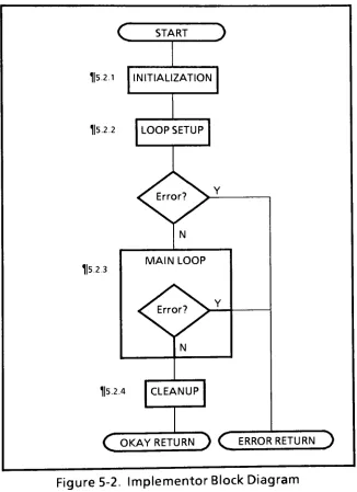
argumentsA5.2 Overview
The
overallexecutionfor
arithmeticimplementor
module operationsis flow-charted in
Figure 5-2.Each
ofthe 4mainblocks in
thefigure is
annotated withthesectionnumber whereit is
described.The entry
point"START" receives controlwhentheBASIC
driver
program makestheappropriatecall. Acompletioncodeis
returnedto theBASIC driver
program attheend ofexecution,indicating
success/failure.C
START115.2.1
INITIALIZATION5.2.2 LOOP SETUP
Error? Y
5.2.3
N
MAIN LOOP
Error?
5.2.4 CLEANUP
[image:24.530.111.437.174.623.2]C
OKAY RETURN)
C
ERROR RETURN)
5.2.1
Initialization
Upon
being
calledfrom
BASIC,
theInitialization block
testsINHIBDMA,and (if
set) turnsoffthe computerdisplay
DMAfunction
(to
stabilizetimemeasurements). Itclears and startsthe intervaltimerwhich will
be
usedtomeasure elapsed executiontime,
unstacks argument valueswhichaccompaniedthecall
from
BASIC,
andstoresthemin
appropriate registers. Theseargumentsconsist oftheaddressesofthearraystobe
manipulated- thespace
for
thesearrayshas been
preallocatedby
the
BASIC
driver
program.Finally,
Initialization
setsup
theMainLoop
withthedesired
calculationfunction
-addition, multiplication,etc.
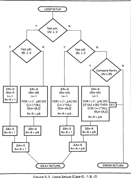
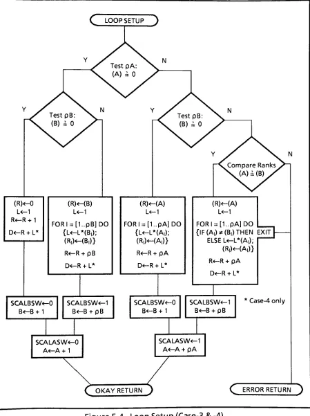
5.2.2
Loop
Setup
The
Loop Setup
block
performsrank and shapecalculationstosetup theresultant'sheader,
and calculatesthenumber ofloop
iterations
reguired ofthe MainLoop. Thelogic for
Loop
Setup
is
flow-chartedin Figures 5-3
and5-4.
Uponentry
to theflow
chart,variable'A'
pointsto thestartofthe
Case-n
argumentA array,'B'
pointsto thestartoftheB array,and
'R'
pointsto thestartofthe
buffer
reserved
for
theR
resultant array.Thus,
'A',
'B'and'R'
pointto the
beginnings
oftheheaders
ofthecorresponding
arrays.Upon
successful exitfrom
theflow
chart,'A'
has been incremented
pasttheheader
topointto thefirst
Adata
element,'B'
to the
firsts data
element and'R'
to the
first
Rresultant element. The Rheader
ahead ofthisfirst
Relementhas been
calculated andfilled in
withboth
rank and shape.AA,
AB
andAR,
theincrement
to'A',
'B'and'R'
pointers attheendof each
loop
iteration,
have been
filled
in (for
cases offixed
elementsize)-witha value of0 if
theargumentis
ascalar,and avalue ofthe
data
element size(6)
if
theargumentis
an array.(The
definitionofadyadic
operationbetween
an
array
and ascalarrequiresthatthescalarbe
repeatedfor
each member ofthearray. Thisis
implemented
by
zeroing incrementation for
scalar'A'
and/or
'B'.)
Lastly,
thenumberofloop
iterations
'L'is
calculated.Error
exits occurfrom
theflow
chartif
theargumentsAandBare arrayswithdissimilar
rankorshape.
The
notationfor
thevalue ofthecontents ofpointer'A'
is (A).
Thatis,
attheentry
to theflow
chart,(A)
is
thefirst item
ofthearray A's
header,
whichis
therank(numberofdimensions)
ofarray
A,
referredtoaspA. Successiveelements
in
theheader
following
therankarethenumber ofelementsper
dimension
(the
shape). Thetotal numberofrequiredmainloop
iterations
'L'
is
calculatedby
finding
theproduct ofthesedimension lengths
usingaFORloop
of'rank'
iterations.
For thevariable
length
case(Case-3)
andpointercase(Case-4)
whereelement sizes are notfixed,
AA,
AB
andAR
arecalculatedwithinthe MainLoop,
and notwithinLoop
Setup.Instead,
Loop Setup
suppliesboolean
valuestosignal the MainLoop
whether ornottoincrement
'A'and/or'B'
Thus
for
these two cases,
Figure
5-4replacesthe initializationofAA,
AB
andAR
withthesetting
ofSCALASW
& SCALBSW.
During
theconstructionof pointercase(Case-4)
arrays,register'R'
addressesthe
2-byte
pointers,andanotherregister 'D'
pointsto thevariable
length data
elements.AR
takesonafixed
value of2
because
ofthefixed
length
ofthepointers,andAD is
thelength
ofthepreviousdata
element.AR
C
LOOP SETUP
AR<-0
(R)-0
L-1 R<-R+1
AR<-6
(R)-(B)
L-1 FORI=
[1..pB]DO
{L<-L*(B,);
(R|)<-(B,)}
R-R+ pB
AB-0
B<-B+1AR<-6
(R)-(A)
L<-1 FORI=[1..pA]DO
(L^L*(A|);
(R|)-(A|)}
R<^R+pA
AB<-6
B-B+pBAR<-6
(R)-(A)
L-1 FORI=[1..pA]DO
{IF(A,)*(B|)THEN
EXIT ELSEL-L*(A|);
(R,)*-(A|)>
R-R+pA
AB<-0
B-B+ 1AA<-0
A-A+1AB-6
B-B+pBAA<-6
A-A+pA
[image:26.530.43.490.84.691.2]OKAY RETURN
C
ERRORRETURN
)
(R)<-0
L-1 R-R+1
D-R+L*
C
LOOPSETUP
)
(R)HB)
L-1
FORI=
[1..pB]DO
{L<-L*(B,);
(R|)-(B|)}
R<-R+pB
D-R+L*
(R)-(A)
L<-1
FORI=
[1..pA]DO
(L^L*(A,);
(R,)-(A,)>
R-R+pA
D<-R+ L*
SCALBSW<-0
B-B+1
SCALBSW<-1 B<-B+pB
(R)-(A)
L-1
FORI=
[1..pA]DO
{IF(A|)*(B,)THEN
EXIT ELSEL<-L*(A,);
(R|)-(A,)}
R<-R+pA
D<-R+ L*
SCALBSW<-0 B<-B+ 1
SCALASW<-0 A<-A+1
SCALBSW<-1 B-B+pB
Case-4
only
SCALASW-1 A<-A+pA
[image:27.530.42.491.86.687.2]OKAY RETURN
C
ERRORRETURN
)
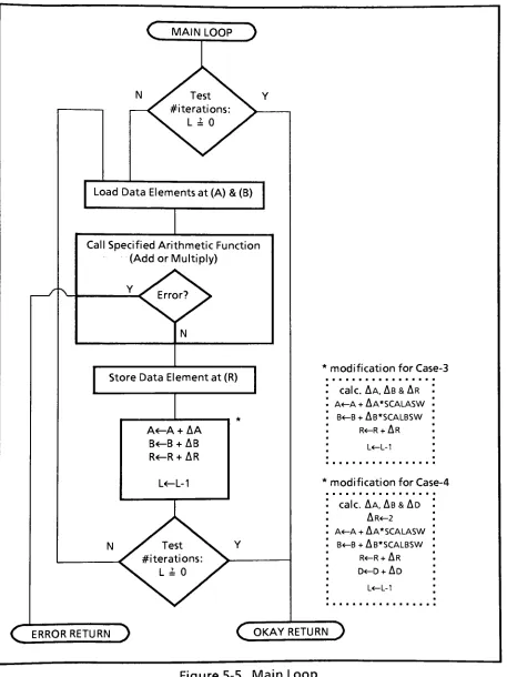
5.2.3
Main
Loop
Figure 5-5
showsthelogic
ofthe MainLoop
block
ofFigure
5-2.Within
the MainLoop
oneachiteration,
pairsofA&Bargument data
elements areprocessed,producing
a resultantdata
element whichis
storedinto
the Rarray. Uponentry
to the MainLoop,
pointer'A'containstheaddress ofthefirst
element of argumentA,
having
been
advancedpastA's header
by
theLoop Setup
block (qv).
Similarly,
pointer'B'addressesthefirst
element of argumentB,
and pointer'R'containstheaddresswherethe
first
resultant elementwillbe
written(past
theRheader).
Execution
oftheMain
Loop
proceedsfor
Literations,
where 'L'wascalculated
during Loop
Setup. Atthe
beginning
ofeachiteration,
thenexttwoargumentdata
elementsaddressedby
(A)
and(B)
respectively
areloaded into
a pairofpage zero registersfor processing
by
thearithmeticfunction
selected
by
theInitialization
block.
Incaseswheredata
elementrepresentations candiffer,
thesimpler
data
elementis
coercedinto
themore complexdata
element'srepresentation,andthemore complexprocessing
algorithmis
chosen.The
arithmeticfunction
processesthetwodata
elementsin
thepage zeroregisters,andleaves
theresultantdata
elementin
oneoftheregisters. Incaseswheredata
element representations aremixed,anattemptis
madetocoercetheresultantdata
elementinto
a simplertype(such
asrounding
offfloating
point3.99999...tointeger
4). Then thedata
elementis
stored atthelocation
addressedby
(R).
At theconclusionofeachiteration,
pointers'A',
'B'and 'R'are incremented
by AA,
AB
andAR
respectively,sothatthey
willpointto thenext elementstobe
processed onthefollowing
iteration.
At theend of
iteration
number'L',
in
general'A',
'B'and
'R'
pointtothe
byte foil owing
thelast
element ofthecorresponding
arrays.The
exceptionto thisstatement occurs whenA,
Band/orRarescalar:
in
such a case noincrementation
takes place,andthepointer continuestopointtothefirst
andonly
element ofthescalardata
structure.Figure
5-5mustbe
modifiedslightly
tohandle
thevariablelength
case(Case-3)
and pointercase(Case-4),
where element size(and hence
theamount ofincrementationattheconclusionof eachloop
iteration)
is
notfixed.
For these twocasesAA,
AB
andAR
are calculatedby
thearithmeticfunction
executed atthebeginning
of eachiteration,
notby
Loop
Setup. Attheendofeachiteration
thedecision
whetheror nottoincrement
eacharraypointeris
providedin
Case-3andCase-4
by
booleans
SCALASWandSCALBSWwhich areinitialized
by
Loop
Setup. Avalue of0
indicates
a scalarrequiring
noincrementation;
avalueof 1indicates
anarrayrequiring
incrementation.
For
thepointercaseonly
(Case-4),
theregister'D'is
incrementedby
AD
attheconclusionof eachiteration.
For thiscaseAD is
calculatedasthe lengthofthejust-calculated resultant, andAR is fixed
at2
-because
theregister'R'
addressesthe 2-bytepointersoftheCase-4array.
5.2.4
Cleanup
The
final
block in
Figure 5-2is
theCleanup block,
whichstopsthetimerand storestheelapsedtimeC
MAIN LOOP
)
Load Data Elements
at(A)
&
(B)
Call Specified Arithmetic
Function(Add
orMultiply)
Error?
N
Store Data Element
at(R)
A<-A+
AA
B<-B+AB
R<-R+AR
L-L-1
C
ERROR RETURN)
*
modification
for Case-3
'
calc.
Aa,
Ab&Ar
'
. A-A+Aa*scalasw
'
. B-B+Ab*scalbsw
'
r<-r+Ar
'
ll-i
;
*
modification
for
Case-4'
calc.Aa,
Ab&Ad
'
AR-2
'.
. A-A+
Aa*scalasw '
. B-B+Ab*scalbsw
'
r-r+
Ar
d-d+Ad
l-l-i
:
C
OKAY RETURN^
[image:29.530.42.499.80.690.2]5.3
Integer Addition
Integer
additionis
implemented
using
asimplealgorithm.First
thealgebraicsignsofthetwo addendsarecompared. Ifthey
arethe same, thesign oftheresultis
thesame asthatofeachaddend,andthemagnitudesofthe twoargumentsare added
in
aloop
thatprocesses abyte from
eachaddendat atime, starting
withtheleast
significantandending
withthemostsignificant.If thesignsofthe twoarguments
differ,
then the twomagnitudes mustbe
comparedtodetermine
whichis larger.
This
is
accomplishedwith aloop
thatcomparesabyte from
one addendwiththecorresponding
byte
oftheother,
starting
withthemost significantbytes.
Equality
causestheloop
to proceedto thenextpair ofbytes.
Assoon as anunequal pair ofbytes is
encountered,thelarger
ofthe twomagnitudes
is
determined.
At that point, thesignoftheresultantis
assignedasthesignofthe
larger
magnitude,
andthesmallermagnitudeis
subtractedfrom
thelarger. This is
accomplished as withmagnitudeadditionabove,starting
withtheleast
significantbytes
andending
withthe most significant.If
themagnitudeshappen
tobe
equalbut
thesignsaredifferent,
theresultantis
assignedas all-zeros, therepresentationfor
+0.
The
integer
addition algorithm always processes5
bytes
ofmagnitudefrom
eachargument, regardlessofthe number ofbytes in
variablelength integers.
Thus,
thevariablelengthintegers
have
tobe
loaded
into
theleast
significant ends oftheaddendregisters, exceptfor
thesignswhich areinserted into
themost significantbyte. Unused high
significantbytes
arezero-filledbefore
additionbegins.
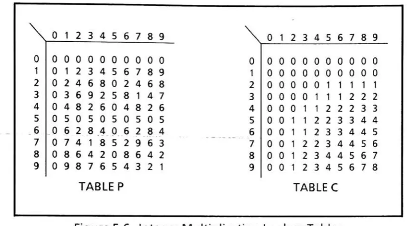
5.4 Integer Multiplication
Integermultiplication
is
implemented using
anoriginalalgorithmbased
uponthelook-uptables
shownin
Figure 5-6. The tableontheleft
givestheleast
significantdigit
oftheproduct ofany
pair ofdigits.
The tableontheright givesthecarry (or
mostsignificant)digit
from
themultiplication ofany
pair ofdigits.
For example,giventhedigits
4 &7,
Table Pyieldstheleast
significantdigit
oftheir product(8),
andTableC
yieldsthemost significantdigit
oftheirproduct(2).
In theactual
implementation (SeeTables.ASM in
AppendixIII),
each ofthe tablesis laid
out as alinear list
ofentries,suchthatthe twodigits
tobe
multipliedcanbe
concatenatedinto
asinglebyte
thatcan
be
usedtodirectly
index
the tableofinterest.
Althoughabyte
canpotentially
address256
locations
the tables PandCare only
160entrieslong.
Thisis because
each nibble contains aBCDdigit,
sothemostsignificantnibbleofthebyte index
canneverexceed 10decimai-See
section7.2for
adiscussion
onoptimizing tablesize.The
tablesP &
C handle only
single-digitarguments,but
thecompleteinteger
multiplieris designed
to
find
theproductofmulti-digitarguments,withtwodigits
packedinto
eachbyte
ofeach argument.To illustrate
theimplementation,
thelong
multiplicationofCDEF
by
ABis detailed in
Figure 5-7. As depicted
by
theshading,ABis
atwo-digitmultiplier packedinto
asinglebyte,
andCDEF
is
a4-digitmultiplicandpackedinto
twoadjacentbytes. The
long
multiplication contains a series oflooked-up
termssuch asPBf
&
Qf- ThenotationPBF
representstheProduct
ofdigits
B & F.PBF
is
asingledigit
whichcanbe looked up in
TablePas defined
above.Similarly,
the notationCBF
representstheCarry
ofdigits
B&
F0
12
3
45
6
7 89
0
1 23
4 56
78
9
0
0 0
0
0
0
0
5
29
6 3
0
8
6
42
5
43
2
1\
0
1 23
4 56
7 89
0
0
0 0
0
0
0
0
0
0
0
10
0
0
0
0
0
0
0
0
0
20
0
0
0
0
1 1 1 1 13
0
0
0
0
1 1 1 22
2 40
0
0
1 1 2 22
3
3
50
0
1 1 2 23
3
4 46
0
0
1 1 23
3
4 45
70
0
1 2 23
4 4 56
80
0
1 23
4 4 56
79
0
0
1 2 3 4 56
78
TABLE
P
TABLE
C
Figure
5-6. Integer Multiplication
Lookup
Tables
D
+
CAc
Pbc
Pbd
<