1
Ultrafast laser parallel micro drilling using multiple annular
beams generated by a spatial light modulator
Zheng Kuang, Walter Perrie, Stuart P. Edwardson, Eamonn Fearon and Geoff Dearden
Laser Group, Centre for Material and Structures, School of Engineering, University of Liverpool, Brownlow Street, Liverpool, L69 3GQ
E-mail: [email protected] or [email protected]
Abstract
Ultrafast laser parallel micro drilling using diffractive multiple annular beam patterns is demonstrated in this paper. The annular beam was generated by diffractive axicon computer generated holograms (CGHs) using a spatial light modulator (SLM). The diameter of the annular beam can be easily adjusted by varying the radius of the smallest ring in the axicon. Multiple annular beams with arbitrary arrangement and multiple annular beam arrays were generated by superimposing an axicon CGH onto a Grating and Lenses (GL) algorithm calculated multi-beam CGH and a binary Dammann grating CGH, respectively. Micro holes were drilled through a 0.03mm thick stainless steel foil using the multiple annular beams. By avoiding huge laser output attenuation and mechanical annular scanning, the processing is ~ 200 times faster than the normal single beam processing.
Keywords
Ultrafast laser, Spatial light modulator, Computer generated holograms, Annular beam, Micro drilling
PACS: 42.40.Jv, 42.62.Cf, 81.20.Wk
1. Introduction
Ultrafast lasers have been widely used for high precision micro-fabrication. The unwanted thermal defects can be avoided due to the ultrashort timescale in which energy is coupled to the electronic system [1 - 3]. When the input processing fluence, F, is kept in the low regime, heat diffusion during the temporal ultrashort pulse duration can be reduced to the nanometer scale [4 - 6]. In order to ensure this ‘thermal free’ processing, huge output attenuation that keeps the fluence sufficiently low is always required [7]. This severely limits the useful throughput.
Parallel processing using diffractive multiple beams generated by a spatial light modulator (SLM) is a novel method to increase the throughput and efficiency of ultrafast laser fabrication [8 - 11]. Applications ranging from surface thin film patterning of transparent couducting oxides (TCOs) [12] and internal 3D refractive index modification of ploy (methyl methacrylate) (PMMA) [13, 14] have been recently reported with the parallel processing technology. However, in this previous research, the shape of the multiple beams was unmodified, remaining circular. The use of other interesting beam shape can make some specific laser micro fabrication more flexible. For example, the generation of different sized annular beams can be used to obtain optical trepanning drilling, which is more efficient than the traditional mechanical trepanning drilling [15 - 17].
2
arbitrary arrangement and multiple annular beam arrays were generated by superimposing an axicon CGH onto a Grating and Lenses (GL) algorithm calculated multi-beam CGH and a binary Dammann grating CGH, respectively. Micro holes were drilled through a 0.03mm thick stainless steel foil using the multiple annular beams. By avoiding huge laser output attenuation and mechanical annular scanning, the processing is ~ 200 times faster than the normal single beam processing.
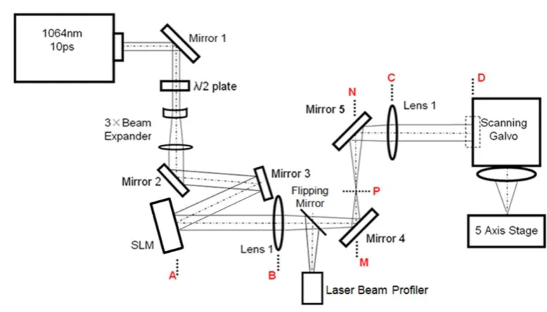
[image:2.595.96.485.203.425.2]2. Experimental and methodology 2.1 Experimental
Figure 1. Experimental Setup
The ultrafast laser system used for this research was a custom made Nd: VAN seeded regenerative amplifier laser system (High-Q IC-355-800ps, Photonic Solutions). Schematic of the experimental setup is shown in figure 1. The laser output (tp = 10 ps, 𝜆 = 1064 nm, R = 5 kHz) passed through a half
wave plate used for adjusting the linear polarization direction, a beam expander (M ≈ ×3), and after reflection on mirrors 1, 2 and 3, illuminated a reflective phase only SLM, a Hamamatsu X10468-03 liquid crystal on silicon (LCoS) device with 800 × 600 pixels and dielectric coating for 1064 nm wavelength (reflectivity η > 95%), oriented at < 10degree angle of incidence. A flipping mirror, placed after lens 1, reflected the beam to a charge-coupled device (CCD) camera-based laser profiler (Spiricon) to observe the reconstructed annular beam patterns when it was flipped into beam line. A 4f-optical system was formed from A to D to remove the unwanted 0-th order beam [11]. The beam then entered a scanning galvanometer with f = 100 mm flat field f-theta lens (Nutfield) producing an agile focusing system. Substrates were mounted on a precision 5-axis (x, y, z, p, q) motion control system (Aerotech) allowing accurate positioning of the substrate surface at the laser focus. The spectral bandwidth, ∆𝜆 < 0.3 nm, was relatively narrow and important in eliminating chromatic dispersion of the SLM [11, 18].
2.2 Methodology
2.2.1 The generation of single annular focus
3
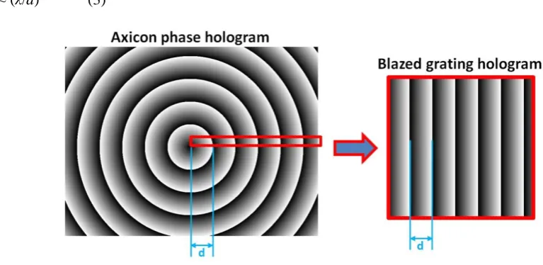
is equal to the spatial period of the blazed grating, d. The blazed grating creates a +1 order beam with a diffraction angle of β, while the axicon generates a diffractive +1 order conical wave. According to the grating equation below,
d (sinα + sinβ) = mλ (1)
where d is the grating period or the radius of smallest ring in the axicon phase, α is the input beam incidence angle, m is the diffraction order and λ is the input beam wavelength, the +1 order diffraction angle:
β ≈ sinβ = (λ/d) – sinα (2)
In our experimental setup, sinα ≈ 0.17 (α ≈ 10 degree) is very small and can be neglected. So,
[image:3.595.82.466.278.465.2]β ≈ (λ/d) (3)
Figure 2. Diffractive axicon CGH (left) and blazed grating CGH (right)
When the diffracted conical wave is focused by the f-theta lens (f = 100mm), an annular focus is created at the focal plane. As shown in figure 3, the diameter (D) of the annular focus can be calculated by:
D = 2r = 2 f tanβ ≈ 2 f β ≈ 2 f λ/d (4)
Since the width of the annular focus is comparable to the 0th order beam waist (2ω
0), the area of the
annular (S) focus can be calculated by:
S ≈ 2ω0 c = 2ω0 πD = 4ω0π f λ/d (5)
4
Figure 3. Annular focus created at the focal plane of the f-theta lens
2.2.2 The generation of multiple annular focuses
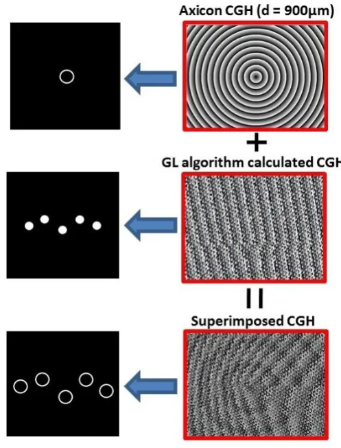
Figure 4(a). Multiple annular beams with arbitrary arrangement generated by the superimposing an axicon CGH onto a GL algorithm calculated CGH – right column: CGHs, left column: reconstructions
[image:4.595.168.417.298.625.2]5
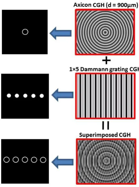
Figure 4(b). 1×5 annular beam array created by superimposing the axicon CGH onto a 1×5 Dammann grating CGH - right column: CGHs, left column: reconstructions
When using GL algorithm, periodic and symmetrical geometry designs (e.g. N×M beam array) of the multi-beam pattern must be avoided to ensure a good uniformity [12, 21, 23]. Therefore, to create a highly symmetrical annular multiple beam array, Dammann grating [22] CGHs can be used instead of the CGHs calculated by GL algorithm [23]. As shown in figure 4(b), a 1×5 annular beam array can be created by superimposing the axicon CGH onto a 1×5 Dammann grating CGH.
2.2.3 The calculation of processing fluence
During experiments, pulse energies (Ep) were directly measured by an energy meter. Peak fluences (F)
can be calculated by
F = 2 Ep /S (6)
where S is the area of the focus. When processing with a single circular Gaussian beam, the fluence is:
F = 2 Ep / (π ω02) (7)
where ω0 is the radius of the Gaussian beam waist. In this case, ω0≈ 11.9μm has been calculated by:
2ω0= 4 λ f M2/ (π Ф) (8)
[image:5.595.178.411.70.382.2]6 F = Ep d / (2nω0π f λ) (9)
where n is the number of annular focuses.
3. Results and discussions
[image:6.595.134.463.192.455.2]3.1 Processing with single annular beam
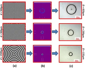
Figure 5. Single annular beam processing – column (a): diffractive axicon CGHs with different radius of smallest ring, d; column (b): annular beams observed by the Spiricon beam profiler; column (c):
optical micrographs showing the annular ablation footprints on a stainless steel sample
Surface ablation of a stainless steel sample using different sized annular beams created by diffractive axicon CGHs is demonstrated in figure 5. The laser intensity distributions measured by the Spiricon beam profiler are presented in column (b). As demonstrated, the irradiance is confined only in the central dot (0th order) and the surrounding ring as depicted in figure 3. Each ablation annular footprint shown in the column (c) was fabricated by 1000 pulses at fluence F ≈ 0.3J/cm2 (approximate 1.5× ablation threshold). As shown, a small circular hole machined by the undiffracted 0th order beam was found in the centre of the D ≈ 420μm annular footprint, but no such holes were observed when D ≈ 250μm and 132μm. This is because higher pulse energy (Ep) was applied to reach the fluence level (F
≈ 0.3J/cm2) when D is larger (i.e. S is larger) and the corresponding 0th order is hence stronger. In this case, for D ≈ 420μm, 250μm and 152μm annular beam, the total input Ep were ≈ 48μJ, 28μJ and 15μJ
and the 0th order energy were measured to be ≈ 0.5μJ, 0.3μJ and 0.15μJ, respectively. Using equation (7), the corresponding fluence of the 0th orders are 0.22J/ cm2, 0.13J/ cm2 and 0.07J/ cm2. Only the 0th order in D ≈ 420μm annular beam has the fluence higher than the sample’s ablation threshold that was measured to be ≈ 0.2J/ cm2.
7
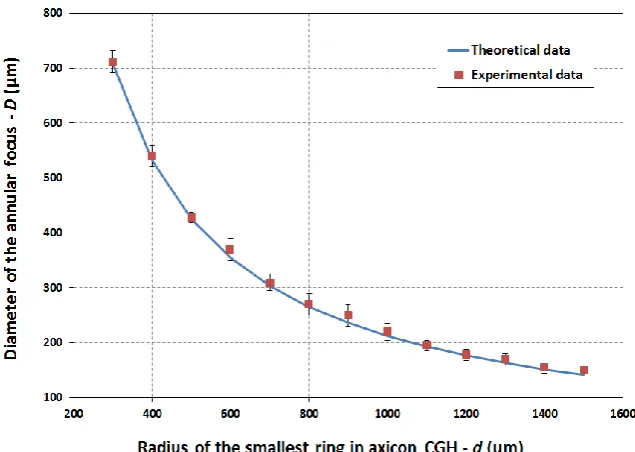
measuring the annular ablation footprint on the stainless steel sample perfectly matches the theoretical data calculated using equation (4).This indicates an excellent accuracy of the theoretical derivation in 2.2.
Figure 6. Diameter of the annular focus versus radius of the smallest ring in axicon CGH
[image:7.595.132.450.125.351.2]The annular beams were used to drill holes with different diameters through a 0.03mm thick stainless steel foil, known as optical trepanning drilling [14, 15]. The laser beam was focused on the upper surface of the stainless steel foil. Since the thickness of the stainless steel foil (~30µm) is comparable to the depth of focus of the f-theta lens, there is no need to adjust the focal position when the laser is drilling through the foil. No processing gases were used during the experiment. As shown in figure 7, the drilled holes with different size are demonstrated in column (a), (b) and (c), generated by annular beams using diffractive axicon CGHs with d = 500μm, 900μm and 1500μm, respectively. 5000 pulses at a fluence of F ≈ 0.3J/cm2 were applied to drill through the foil sample. The entrance hole diameters are ≈ 426μm, 255μm, and 160μm, while the exit hole diameters are ≈ 420μm, 250μm, and 153μm. The darker area that appears around the entrance hole (c column) is not a heat-affected zone. It was formed by micro/nano sized particles generated during the processing and can be easily cleaned up by ultrasonic cleaning.
[image:7.595.122.470.554.734.2]8 3.2 Processing with multiple annular beam patterns
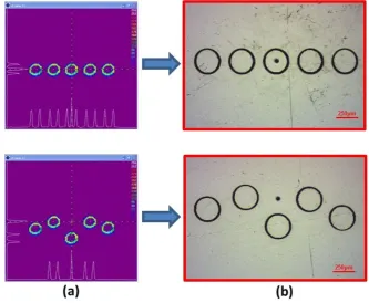
Multiple(five) annular beam patterns with excellent uniformity were generated using the superimposed CGHs which has been discussed in 2.2.2. As shown in figure 8, pattern profiles observed by the laser profiler (Spiricon) are shown in column (a), while optical micrographs showing surface ablation footprints on a stainless steel sample are demonstrated in column (b). The footprints were fabricated by 1000 pulses at fluence (F) ≈ 0.3J/cm2, calculated using equation (9). Since five annular beams (D ≈ 250μm) were generated simultaneously, the focal area (S) and the pulse energy (Ep) required to reach the fluence level are five times larger than the single annular beam. In this case,
the measured total input Epwas ≈ 150μJ, where huge attenuation of the laser output was avoided. As
[image:8.595.132.466.282.556.2]shown in column (b), a small unwanted micro hole corresponding to the 0th order is present. There are two methods to prevent the 0th ordering from damaging the sample. One is to physically block the 0th order at the Flourier plane of the 4f optical system using a small target [11], and the other is to defocus the 0th order at the processing plane by adding a Fresnel phase onto the CGH[18].
Figure 8. Multiple(five) annular beam patterns generated using the superimposed CGHs - column (a): pattern profiles observed by the laser profiler (Spiricon); column (b): optical micrographs showing
surface ablation footprints on a stainless steel sample
9
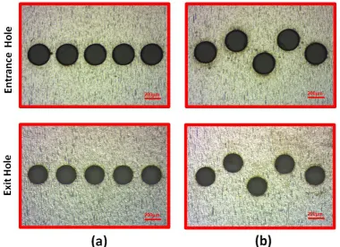
[image:9.595.105.486.74.350.2]Figure 9. Optical micrographs showing the entrance and the exit holes of a stainless steel foil sample drilled by multiple(five) annual beam patterns
Table 1. Comparison of drilling five holes through a 0.03mm thick stainless steel foil between single circular beam mechanical trepanninga and five annular beam pattern optical trepanning
Single circular beam five annular beam
Area of focus - S (μm2) ~445 b ~88350 c
Pulse energy - Ep(μJ) ~0.7 ~150
Peak fluence - F (J/cm2) ~0.3 ~0.3
Ent. hole diameter - Dent (μm) 264.0 ± 5.0 262.0 ± 7.0 (array pattern)
268.0 ± 11.0 (random pattern)
Exi. hole diameter - Dexi (μm) 246.0 ± 4.0 247.0 ± 6.0 (array pattern)
248.0 ± 9.0 (random pattern)
Drill time - t (s) ~200 ~1
a. The circular beam was mechanically scanned around a circle (dia. ≈ 250μm) by the scanning galvanometer at a speed of v = 2mm/s and 100 times overscan to drill through the sample b. Calculated by S = π ω02, where ω0 ≈ 11.9μm is the radius of the beam waist
c. Calculated by equation (5) multiplied by n = 5, i.e: S ≈ 4 n ω0 π f λ / d = 20 ω0π f λ / d, where d = 900μm
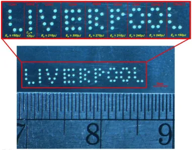
By combining real time control of the CGHs with scanning, the processing has significant potential to produce complicated arbitrary micro-drilling patterns. Figure 10 shows a micro-drilling result of a ‘Liverpool’ pattern, which comprises 63 holes drilled through a 0.03mm thick stainless steel foil with entrance diameter ≈ 264.0 ± 10.0μm and exit diameter ≈ 245.0 ± 9.0μm. The pattern was generated by applying 9 CGHs in turn, each of which generated multiple annular beams and formed one letter. The scanning galvanometer scanned the beam to a correct position when switching the CGH. During the processing, each CGH was given 1 second dwelling time, allowing 5000pulses applied to drill through the sample. Since different CGH created different number of annular beams, the applied pulse energy Ep varied when changing the CGH to ensure a constant fluence (F ≈ 0.3J/cm2), as shown in
[image:9.595.71.531.433.548.2]10
[image:10.595.106.488.113.412.2]synchronized with the scanning galvanometer positioning and the pulse energy adjustment. If the synchronization is achieved, the whole pattern should be completed in about 9 seconds.
Figure 10. ‘Liverpool’ pattern generated by applying 9 CGHs in turn 4. Conclusions
Ultrafast laser parallel micro drilling using diffractive multiple annular beam patterns is demonstrated in this paper. The annular beam was generated by diffractive axicon computer generate holograms (CGHs) using a spatial light modulator (SLM). The diameter of the annular beam can be easily adjusted by varying the radius of the smallest ring in the axicon. Multiple annular beams with arbitrary arrangement and multiple annular beam arrays were generated by superimposing an axicon CGH onto a Grating and Lenses (GL) algorithm calculated multi-beam CGH and a binary Dammann grating CGH, respectively. Micro holes were drilled through a 0.03mm thick stainless steel foil using the multiple annular beams. By avoiding huge laser output attenuation and mechanical annular scanning, the processing is ~ 200 times faster than the normal single beam processing.
Acknowledgements
11 References:
[1] Du D, Liu X, Korn G, Squier J, Mourou G 1994 Laser-induced breakdown by impact ionization in SiO2 with pulse widths from 7 ns to 150 fs, Appl. Phys. Lett. 64 3071–3073. [2] Liu X, Du D, Mourou G 1997 Laser ablation and micromachining with ultrashort laser pulses,
IEEE J. Quant. Electron 33 1706–1716.
[3] Chichkov B N, Momma C, Nolte S, Alsvenleben F von, Tunnermann A 1996 Femtosecond, picoseconds and nanosecond laser ablation of solids Appl. Phys. A 63 109–115.
[4] Harzic R Le, Breitlung D, Weikert M, Sommer S, Fohl C, Valette S, Donnet C, Audouard E, Dausinger F 2005 Pulse width and energy influence on laser micromachining of metals in a range of 100 fs to 5 ps Appl. Surf. Sci. 249 322–331.
[5] Perrie W, Gill M, Robinson G, Fox P, O’Neill W 2004 Femtosecond laser microstructuring of aluminium under helium Appl. Surf. Sci. 230 50–59.
[6] Luft A, Franz U, Emsemann A, Kasper J 1996 A study of thermal and mechanical effects on materials induced by pulsed laser drilling Appl. Phys. A 63 93–101.
[7] V V Semak, B R Campbell and J G Thomas, 2006 On the possible effect of pedestal pulse on material removal by ultrahigh intensity laser pulses, J. Phys. D: Appl. Phys. 39 3440.
[8] Hayasaki Y, Sugimoto T, Takita A, Nishida N 2005 Variable holographic femtosecond laser processing by use of a spatial light modulator Applied Physics Letters 87 031101.
[9] Hasegawa S, Hayasaki Y, Nishida N 2006 Holographic femtosecond laser processing with multiplexed phase Fresnel lenses Optics Letters 31 1705–1707.
[10] Kuang Z, Perrie W, Leach J, Sharp M, Edwardson S P, Padgett M, Dearden G, Watkins K G 2008 High throughput diffractive multi-beam femtosecond laser processing using a spatial light modulator Applied Surface Science 255 (5) 2284–2289.
[11] Kuang Z, Liu D, Perrie W, Edwardson S, Sharp M, Fearon E, Dearden G, Watkins K G, Fast parallel diffractive multi-beam femtosecond laser surface micro-structuring Applied Surface Science 255 (13–14) (2009) 6582–6588.
[12] Kuang Z, Perrie W, Liu D, Fitzsimons P, Edwardson S P, Fearon E, Dearden G, Watkins K G 2012 Ultrashort pulse laser patterning of indium tin oxide thin films on glass by uniform diffractive beam patterns Applied Surface Science 258 7601–7606.
[13] Liu D, Kuang Z, Perrie W, Cheng J, Shang S, Edwardson S P, Fearon E, Dearden G, Watkins K G 2010 High-speed uniform parallel 3D refractive index microstructuring of poly(methyl methacrylate) for volume phase gratings Applied Physics B 101 (4) 817–823.
[14] Liu D, Perrie W, Kuang Z, Scully P J, Baum A, Liang S, Edwardson S P, Fearon E, Dearden G, Watkins K G 2012 Multi-beam second harmonic generation in beta barium borate with a spatial light modulator and application to internal structuring in poly(methyl methacrylate) Applied Physics B 107 (3) 795–801.
[15] Zeng D, Latham W P, Kar A 2005 Two-dimensional model for melting and vaporization during optical trepanning Journal of Applied Physics 97 (10) 104912.
[16] Zeng D, Latham W P, Kar A 2006 Characteristic analysis of a refractive axicon system for optical trepanning Optical Engineering 45 (9) 094302.
[17] Rioux M, Tremblay R, and Belanger P A 1978 Linear, annualr, and radial focusing with axicons and applications to laser machining Applied Optics 17 (10) 1532-1536.
[18] Kuang Z, Perrie W, Liu D, Edwardson S, Cheng J, Dearden G, Watkins K G 2009 Diffractive multi-beam surface micro-processing using 10ps laser pulses Applied Surface Science 255 (22) 9040–9044.
12
[20] Leach J, Wulff K, Sinclair G, Jordan P, Courtial J, Thomson L, Gibson G, Karunwi K, Cooper J, Laczik Z J, Padgett M 2006 Interactive approach to optical tweezers control Applied Optics 45 897–903.
[21] Curtis J E, Schmitz C H J, Spatz J P 2005 Symmetry dependence of holograms for optical trapping Optics Letter 30 2086–2088.
[22] Dammann H, Gortler K, 1971 High-efficiency in-line multiple imaging by means of multiple phase holograms Optics Communications 3 (5) 312–315.