AST·3GTM Model 1
Enhanced Graphics Adapter
for the
IBM Personal Computer,
IBM.PC-XT, PC-AT,
And Other
IBM-Compatible Machines
User's Manual 000337-001 A
March 1986
AST Research, Inc. Irvine, California
First Edition (March 1986)
AS1=-3G Model 1, SixPakPlus, MonoGraphPlus, Preview!, and Advantage! are trademarks of AST Research, Inc.
IBM is a registered trademark of International Business Machines Corporation.
Changes are periodically made to the information contained in this manual; these changes will be incorporated into new editions.
In view of demonstrated product reliability and comprehensive warranty policies, AST Research, Inc. does not normally provide schematics or material lists. AST recognizes that some customers with a large installed base of AST products want supportive documentation for their own service organizations. In such cases, customers should contact AST Research corporate offices to consider an appropriate nondisclosure agreement to obtain this documentation.
A Product Comment Form is provided at the back of this publication. If this form has been removed, please address your comments to: AST Research, Inc., Attn: Product Marketing, 2121 Alton Ave., Irvine, CA 92714. AST Research may use or distribute. any of the information you supply in any way it deems appropriate without incurring any obligations whatsoever.
Copyright© 1986 AST Research, Inc. All rights are reserved, including those to reproduce this book or parts thereof in any form without permission in writing from AST Research, Inc.
WARNING
TABLE OF CONTENTS
SECTION 1. INTRODUCTION 1-1
1.1 Checklist 1-2
1.2 Compatibility and System Requirements , 1-3
1.3 How to Use This Manual 1-4
1.3.1 Related Documentation 1-4
1.3.2 Manual Outline 1-4
SECTION 2. OVERVIEW 2-1
2.1 Some Terms You Should Know 2-1
2.2 Versatility of the AS1=-3G Graphics Display Adapter .. 2-2 2.3 Monitor and Display Adapter Compatibility 2-2 2.3.1 IBM 5151 Monochrome Display Monitor 2-4 2.3.2 IBM 5153 Color Display Monitor 2-4 2.3.3 IBM 5154 Enhanced Color Display Monitor 2-5 2.4 Software/Hardware Compatibility
Limitations with AS1=-3G 2-5
2.5 Using Multiple Display Adapters 2-6
SECT:tON 3. CONFIGURATION AND INSTALLATION 3-1
3.1 AS1=-3G Default Configuration 3-2
3.2 Changing the Default SW1 Configuration 3-4 3.3 Changing the Monitor Select Jumper Block 3-5
3.4 Configuring the Parallel Port 3-6
3.5 Installing Your AS1=-3G 3-9
SECTION 4. PARALLEL PORT 4-1
4.1 I/O Address and Interrupt Assignments 4-1 4.2 Parallel Port Pinout Specifications 4-2 4.3 Configuring External Parallel Devices 4-3
TABLE OF CONTENTS
(Continued)4.5 Interrupt-Driven Parallel Printer Software 4-4 4.6 Parallel Port Diagnostic Testing 4-4
SECTION 5. DIAGNOSTICS 5-1
5.1 Starting the Diagnostics Program 5-2
5.2 The Configuration Screen 5-2
5.3 The Test Screens 5-3
5.3.1 Monochrome Display Tests 5-4
5.3.2 Color Display Tests 5-10
5.3.3 Enhanced Color Display Tests 5-17
SECTION 6. PRODUCT REPAIR PROCEDURE 6-1
SECTION 7. ENHANCEMENT OPTIONS 7-1
7.1 Installing the Memory Upgrade Kit 7-1 7.2 Installing the Parallel Port Upgrade Kit 7-4
APPENDIX A. FEATURE CONNECTOR A-1
APPENDIX B. LIGHT PEN INTERFACE B-1
Figures
Figure 3-1. Installation Overview 3-1
Figure 3-2. AST-3G Model 1 Display Adapter Layout
(Default Configuration) 3-2
Figure 3-3. SW1 Switch Block Default Configuration 3-5 Figure 3-4. Monitor Selection Jumper Block 3-6
Figure 3-5. Removing the PC Cover 3-10
Figure 3-6. Removing the PC-AT Cover 3-11 Figure 3-7. Switch Block 1 on the PC and PC-XT 3-12 Figure 3-8. Parallel Port Ribbon Cable and Bracket 3-13 Figure 3-9. Installing Ribbon Cable on the AS1=-3G 3-13 Figure 3-10. Installing the Plastic Card Guide 3-14 Figure 3-11. Installing the AST-3G Adapter 3-15
TABLE OF CONTENTS
(Continued)
Figure 5-1. Configuration Screen 5-2
Figure 5-2. Monochrome Text Attributes Test
(Blinking) 5-4
Figure 5-3. Monochrome Text Attributes Test
(Intensified) 5-5
Figure 5-4. Monochrome Character Set Test
(9 x 14 pixel character box) 5-6
Figure 5-5. Monochrome Character Set Test
(8 x 8 pixel character box) 5-7
Figure 5-6. Monochrome Memory Pages Test 5-8 Figure 5-7. Monochrome Intensity Test 5-9 Figure 5-8. Color Text Attributes Test
(Blinking) 5-10
Figure 5-9. Color Text Attributes Test
(Intensified) 5-11
Figure 5-10. Color Character Set Test,
40-Column Wide Format 5-12
Figure 5-11. Color Character Set Test,
80-Column Wide Format 5-13
Figure 5-12. Color Memory Pages Test 5-14 Figure 5-13. Color 320 x 200 4-Color Graphics Test 5-15 Figure 5-14. Color 640 x 200 2-Color Graphics Test 5-16 Figure 5-15. Enhanced Text Attributes Test
(Blinking) 5-17
Figure 5-16. Enhanced Text Attributes Test
(I ntensified) 5-18
Figure 5-17. Enhanced Character Set Test (8 x 8
pixel characters, 40 columns) 5-19 Figure 5-18. Enhanced Character Set Test (8 x 14
pixel characters, 80 columns) 5-20 Figure 5-19. Enhanced Character Set Test (8 x 8
pixel characters, 43 Rows) 5-21
Figure 5-20. Enhanced Memory Pages Test 5-22 Figure 5-21. Enhanced 320 x 200
4-Color Graphics Test 5-23
Figure 5-22. Enhanced 640 x 200
2-Co1Qr Graphics Test 5-24
Figure 5-23. Enhanced 640 x 350,
TABLE OF CONTENTS
(Continued)Figure 7-1. AST-3G Adapter Upgrade Chip Placement 7-2
Figure A-1. Feature Connector Layout A-3
Figure B-1 Light Pen Interface Connector B-1
Table 2-1. Table 2-2. Table 3-1. Table 3-2. Table 3-3. Table 3-4. Table 3-5. Table 3-6. Table 4-1. Table 4-2. Table 4-3. Table A-1. Table B-1 vi Tables
AS1=-3G Graphics Modes 2-3
AS1=-3G Model 1 Text Modes 2-4
AST-3G Model 1 Default Configuration 3-3
SW1 Switch Settings 3-4
Parallel Port I/O Assignments
Without Port on Another Display Card
Fixed as LPT1 3-7
Parallel Port I/O Assignments With Port on Another Display Card
Fixed as LPT1 3-7
Parallel Port Configuration
(Without Port on Another Display Card
Fixed as LPT1) 3-8
Parallel Port Configuration
(With Port on Another Display Card
Fixed as LPT1) 3-9
PC Parallel Port I/O & IRQ Assignments (With Port on another Display Card
Fixed as LPT1) 4-2
PC Parallel Port I/O &IRQ Assignments (Without Port on Another Display Card
Fixed as LPT1) . . . 4-2
DB25S Parallel Port Pinouts 4-3
Feature Connector Inputs and Outputs A-2
SECTION 1
INTRODUCTION
The AST-3GTM Model 1 graphics display adapter (hereafter referred to as AST-3G) provides advanced color and high-resolution graphics capabilities for the IBM® Personal Computer (PC), PC-XT, PC-AT, and most IBM-compatibles. AST-3G, AST's third generation graphics product, is extremely versatile because it is compatible with all IBM PC display monitors (and equivalents), and can perform the functions of three· IBM display adapters.
AST-3G comes equipped with either 64 or 256 kilobytes (KB) of memory, so that it is not necessary to acquire any
supplemental memory to use the ASl=-3G card. ASl=-3G features include:
• Compatibility with three types of IBM monitor: - IBM 5151 Monochrome Display (MD). - IBM 5153 Color Display (CD).
- IBM 5154 Enhanced Color Display (ECD).
• Performs the functions of three IBM display adapter cards:
- IBM Monochrome Display and Printer Adapter (MDA).
- IBM Color/Graphics Adapter (CGA) with some limitations. (Refer to Section 2.4).
- IBM Enhanced Graphics Adapter (EGA). • Can coexist with either the MDA or CGA.
Introduction
• Using eGA capabilities, provides 640 x 200 and 320 x 200 pixel resolutions, and 16-color graphics. • Using EGA capabilities, provides 640 x 350 pixel
resolution, with use of 16 colors simultaneously from a color palette of up to 64 different colors.
• Random access memory (RAM)-based, loadable character generator capable of generating up to 512 displayable characters for use in any application (such as scientific notation and foreign language characters) .
• Supports up to 43 lines of 80-column text.
• Provides smooth, flicker-free horizontal and vertical scrolling.
• 256 KB of on-board graphics memory supports up to eight graphics pages in 320 x 200 pixel, 16-color mode.
• Designed using advanced VLSI technology for speed, reliability, and compatibility.
• Provides a feature connector, light pen interface, and an optional parallel port.
1.1 Checklist
Before getting started, check that your AST-3G Model 1 package includes the following items:
• AST-3G graphics adapter. • AS-':3G User's Manual.
• AST-3G diagnostics diskette.
Introduction
Two optional upgrade packages are available for your AS1=-3G Model 1 adapter:
• AS1=-3G Model 1 Memory Enhancement Kit (Part Number 500305-006).
• AST-3G Model 1 Parallel Port Enhancement Kit (Part Number 500305-005).
1.2 Compatibility and System Requirements
The minimum hardware requirements for operation with AS1=-3G are:
• An AS1=-3G board with 64 KB. To utilize fully the capabilities of AS1=-3G, the recommended amount of on-board graphics memory is 256 KB.
• An IBM PC, PC-XT, PC-AT, or IBM-compatible with one floppy diskette drive and an unused full-length expansion slot.
• One of the following types of monitor is necessary - An IBM 5154 Enhanced Color Display or 350-line,
64-color RGB/R'G'B~compatible.
- An IBM 5153 Color Display or 200-line, 16-color RGBI-compatible.
- An IBM 5151 Monochrome Display or compatible TTL monochrome monitor.
The AS1=-3G diagnostics software is compatible with DOS 2.0 or later, or an MS-DOS equivalent.
Introduction
1.3 How to Use this Manual
This section provides a list of related documentation and an outline of the manual.
1.3.1 Related Documentation
You may find it useful to have the following documents for reference:
• IBM Disk Operating System (DOS) Manual. • IBM PC Guide to Operations.
• IBM PC Technical Reference Manual. • IBM PC-AT Guide to Operations.
• IBM PC-AT Technical Reference Manual. • IBM PC-AT Installation and Setup Manual.
NOTE
If you need AS'-:'3G Model 1 programming information, call AST Technical Support for details.
1.3.2 Manual Outline SECTION 1: INTRODUCTION
Describes the features of AST-3G, and provides information on system requirements, and related documentation.
SECTION 2: OVERVIEW
Provides a detailed description of how AS'-:'3G functions with different monitor types. Also describes the different graphics adapters the AST-3G can simulate and coexist with in one system.
Introduction
SECTION 3: CONFIGURATION AND INSTALLATION
Includes instructions on setting AST-3G adapter switches and PC system switches, and a series of steps to install AST-3G in your PC.
SECTION4: PARALLEL PORT
Describes the AST-3G parallel printer port in detail. SECTION5: DIAGNOSTICS
Tells you how to use the diagnostics program that comes with AST-3G.
SECTION6: PRODUCT REPAIR PROCEDURE
Describes the product repair procedure to follow if your AS'-:3G ever needs repair.
SECTION 7: ENHANCEMENT OPTIONS
Describes how to install the memory and parallel port upgraqe kits for your ASl=-3G.
APPENDIX A: FEATURE CONNECTOR
Describes the ASl=-3G feature connector in detail.
APPENDIX B: LIGHT PEN INTERFACE
1-6
SECTION 2
OVERVIEW
This section provides an overview of the different
combinations of adapters and monitors you can choose from when using an AS':'3G graphics display adapter. Once you have determined which combination of adapters and monitor you will be using, you can configure and install your AST-3G adapter as described in Section 3 of this manual.
2.1 Some Terms You Should Know
The following definitions describe terms used throughout this manual.
Bit Map
A computer representation that defines the color and intensity of each. pixel on a raster screen required to create an image.
Pixels
The smallest unit available for display on a raster screen, representing a single graphics point. Also called picture elements.
Raster display
The predominant type of CRT display. It operates
Overview
Resolution
The number of pixels displayed on a monitor per horizontal line, by the number of horizontal lines displayed on the vertical axis (for example, 640 x 350 indicates 640 pixels wide by 350 lines of pixels vertically).
VOl (Virtual Device Interface)
A software interface method that allows applications programs to be written independent of graphics hardware.
2.2 Versatility of the AST-3G Graphics Display
Adapter
AS'-:'3G is a versatile graphics display adapter that is compatible with three types of IBM monitor and three IBM display adapters. Many IBM-compatible monitors and adapters are also compatible with AS'-:'3G. The graphics capabilities available with AS'-:'3G, including resolution and number of colors, vary depending on what monitor type is used and which display adapter you wish to simulate.
The capabilities of AST-3G may be affected when other graphics display adapters are installed in your system. The graphics features of specific applications software packages may also be affected by the monitor and adapter configuration of your AS'-:'3G.
2.3 Monitor and Display Adapter Compatibility
The AS1=-3G can be used with several IBM monitors and display adapters:
• 5151 Monochrome Display (MDl designed· for use with the Monochrome Display Adapter (MDA) (Section 2.3.1)
Overview
• 5153 Color Display (CD) designed for use with the Color/Graphics Adapter (CGA) (Section 2.3.2). • 5154 Enhanced Color Display (ECD) designed for
use with the Enhanced Graphics Adapter (EGA) (Section 2.3.3).
Tables 2-1 and 2-2 summarize all possible adapter/monitor combinations, and the resulting graphics and text capabilities or modes. These modes are determined by the software package and display monitor that you are using with your AS':3G adapter.
Table 2-1. ASJ:.3G Graphics Modes. Adapter Number Memory
AST-3G of Pages Resolution Monitor Simulates (1) Colors (Max.) (h x v) Required (2)
EGA 16/64(3) 2 640 x 350 ECO
EGA 16 4 640 x 200 CO,ECO
EGA 16 8 320 x 200 CO,ECO
EGA 4/64 1 640 x·350 ECO
EGA 2 (4) 2 640 x 350 MD
CGA 4 1 320 x 200 CD/ECD
CGA 2 1 320 x 200 CD/ECD
CGA 2 1 640 x 200 CD/ECD
NOTES FOR TABLES 2-1 and 2-2
(1) EGA = Enhanced Graphics Adapter, CGA = Color Graphics Adapter, MDA = Monochrome Display and Printer Adapter (2)ECD = IBM 5154 Enhanced Color Display Monitor,
CO
=
IBM 5153 Color Display Monitor, MD=
IBM 5151 Monochrome Display Monitor.(3) 16 displayable colors with a 64-color palette to choose from. Requires 256 KB of on-board graphics memory.
Overview
Table 2-2. AS'J=.3G Model 1 TextModes.
Adapter Number Character
AST-3G of Pages Size Characters Monitor Simulates(1) Colors (Max.) (pixels) per screen Needed(2)
EGA 16/64 (3) 2 8
x
14 80x
25 ECD EGA 16/64 (3) 8 8x
8 80x
43 ECDCGA/EGA 16 8 8
x
8 80x
25 CD/ECOCGA/EGA 16 8 8
x
8 40x
25 CD/ECOCGA/EGA 2 8 8
x
8 80x
25 CD/ECOCGA/EGA 2 8 8
x
8 40x
25 CD/ECOMOA/EGA 2 4 9
x
8 80x
43 MOMOA/EGA 2 8 9
x
14 80x
25 MODescriptions follow of each type of IBM monitor. Some information is also included about the type of graphics adapter most often used with that monitor.
2.3.1 IBM·5151 Monochrome Display Monitor
The IBM 5151 Monochrome Display was designed to be used with the IBM MDA. The MD monitor has a screen refresh rate of 50 Hz (non-interlaced), and a maximum bandwidth of 16.257 MHz. The MD monitor is transistor-transistor logic (TTL) compatible and has a horizontal scan frequency of 18.432 KHz.
2.3.2 IBM 5153 Color Display Monitor
The IBM 5153 Color Display was designed to work with the IBM CGA. The CD monitor can display up to 16 different colors, by combining digital outputs of red, green, blue and intensity values. Monitors of this type are called Digital RGB monitors because they combine the pure colors red, green and blue to create color variations. The CD monitor has a high-contrast black screen. There are many IBM-compatible Digital RGB monitors; however, some of them provide only 8 colors instead of 16.
Overview
The maximum bandwidth of the CD monitor is 14.318 MHz. The screen refresh rate is 60 Hz (non-interlaced). The CD is TTL-compatible, with a horizontal scan frequency of 15.750 KHz.
2.3.3 IBM 5154 Enhanced Color Display Monitor
The IBM 5154 Enhanced Color Display (ECD) was designed to take advantage of the unique capabilities of the Enhanced Graphics Adapter (EGA). The ECD monitor is extremely versatile in that it can support software written for either the EGA or the CGA. For the ECD monitor, the screen refresh rate is 60 Hz. The horizontal scan rate can be either 15.75 KHz or 21.850 KHz. This monitor is considered to be an RGBI monitor because each color can be intensified respectively.
NOTE
If you are planning to use an AS-y:.3G Model 1 graphics display adapter with a new Enhanced Color Display, be sure to get a demonstration of that monitor with the AS1=-3G display adapter and appropriate EGA .software, to ensure that it provides. the
capabilities you are looking for.
2.4 Software/Hardware Compatibility Limitations
with AST-3G
AS1=-3G is fully compatible with IBM's Enhanced Graphics Adapter (EGA). As a result of this, AS1=-3G is among the devices supported by the Virtual Device Interface (VOl) as described by IBM and Graphics Software Systems (GSS). Any software written employing the VOl interface will run on AS1=-3G with an EGA driver.
Overview
2.5 Using Multiple Display Adapters
You may wish to install your AS'-:'3G in your computer and use it in one of the operating modes described in Tables2-1 and
2-2. However, depending on your software applications, you may wish to install your AS'-:'3G along with another coexisting display adapter.
The AS'-:'3G can only be used with another display adapter if one adapter is operating in a color mode, and the other is in a monochrome mode. For exam'ple, if an AS'-:'3G coexists with a eGA, then the AS1=-3G must be configured in monochrome mode because the CGA is only capable of operating in a color mode. Likewise, if an AS'-:'3G coexists with an MDA, then the AS'-:'3G must be set up as a color adapter since the other adapter is for monochrome only.
Two coexisting adapters cannot be configured as the same type of adapter-for example, an AS'-:'3G adapter cannot emulate an MDA when another MDA is coexisting. The combinations of display adapters which are
not
possible include the following:• AS'-:'3G with AS'-:'3G. • AS'-:'3G with EGA.
• AS'-:'3G (in any color mode) with CGA.
When two display adapter cards do coexist, you must specify which adapter is "primary" and which is "secondary". This is accomplished through switch settings on the AS'-:'3G, which are described in Section 3. The adapter designated as primary will be the adapter in use when you boot up your system; the secondary card will not be used unless it is activated through a DOS MODE command.
For example, to switch over to a monochrome display adapter designated as secondary from a different primary card, you would enter the following command at the DOS prompt:
A> MODE MONO
<
Enter>Overview
Conversely, to switch over to a color display adapter designated as secondary from a different primary display adapter, you would enter the following command at the DOS prompt:
A> MODE COSO
<
Enter>2-8
SECTION 3
CONFIGURATION AND
INSTALLATION
Figure 3-1 is an overview of the steps needed to configure and install your AS1=-3G display adapter.
Start
Verify the AS1=-3G display adapter's default configuration (Section 3.1).
Yes Change the default ~-..., configuration
(Section 3.2).
No
Get your PC ready and install the AS1=-3G Model 1 (Section 3.5).
Use the diagnostics program to check that your AS-r:3G is working properly. (Section 5).
Default: EGA, 80.x 25, enhanced, primary o o :::s ... cO' r::
a
0' :::s Q) :::s a. 5" fA [ [ c)' :::s!N
..I.»
en
If
CN C) C (I)Dr
c
::;o
o
~ -ItcC·
c
Dl
...
o·
~ »:TI ~.co ....,c w~ QCD w a. I _. N en en ~:::T s:u 0 '< ~ s:u en 0...-+ s:u :::T "2. CD CD a. :"'" CD -+-s:u c: ;::; -+-s:u Q. o ~ '< C) o :::::s-+-cO'
c: ~ ~o'
:::::s o -+-..-+ :::T CD P2-Light Pen Interface SW1"OFF"
I -.
OPEN-U~~U
"ON" I 1 2 3 4
Monitor Connector J4-Feature
Connector (32-pin)
Memory Jumper Block (256 KB default)
E5
LPT2 or LPT3 Jumper Block
E7 E8
-" Jumper Block
I
!.tfl{fl{.I~~.I
E10Base1/0 ·Address
(3xx default) LPT10r LPT2 P3-Parallel
E1 E2 Jumper Block Port Connector
• i<.~ :',J".~jl \ . L ( 2 6 _Pin)
- ---#---1
_ _ _ .-~ ";~:~~,,.;~:..t,,'"'<:...:~25
~ c=JD;;DD:>c=JD~c=:JD~
c=:J \c=J~D~
~ ~o.~Qo~Dapo, ~O
P!Jm:ii?'l
I}
I
I
~ ~ ~ ~ ~L~~l~rnIIIl...
~(_ _.-_
.
~~ D::pD::D~ l===JD~5c:=J~~ ~ D~c=:J ~c=:J mnnn;~1
I
c=Jo~
[
Jf==JD5~ ~GJ~ ~D?l~
0..
gliC=J....~~.,
s n c:=JDG f7--.:=JD:l' rb r: n c r ; JJIII ~ JI
~ 0 ~ ~ ~Jl· 0
lfL
;Ji3 ~ . E7E8 •c=:JD:: _I :c=;~u~~
_
~ ~Q;o/;(1EBc::Jcj ~r~."""
D+J;• ; U8 '3 AST-3G U26 1 ~ ~ PI I . . . . .0
• , L
:!! CQ c: Cil CIJI !\) ~.~ Q)(I) 'g~ c: CIJ ...Ci)
ore
(I) 0Q;'Q. c:
!!.
--...
° 0o ...
:::1 (I) ~-a CQD) C:'oc:: Ql~ ~.Q.o
D)~-a•
..
(I)W
I
Configuration and Installation
Table 3-1 summarizes the ASl=-3G adapter's default factory configuration.
Table 3-1. ASJ:.3G Modell Default Configuration
Parameter Default Comments
Card Type, EGA, The SW1 switch block provides the Mode, 80 x 25 text, power-up graphics configuration for the Monitor, ECO monitor, AS':3G. Refer to Table 3-2 for all the Primary Primary. possible switch settings and
(SW1-1 OFF, configurations. SW1-2 ON,
SW1-3 ON, SW1-4 OFF.)
Monitor ECO monitor. This jumper block indicates the type of Type (Plug at jumper monitor in use. If a monitor other than an
block position ECO is used, move plug to position E9. E10.)
AST-3G Either 64 KB or The default setting for· memory varies on-board 256 KB. depending on whether your AS':3G board graphics (Plug at jumper has 64 KB or 256 KB. You only need to memory. block position E5 change the default setting if you are
for 256, no plug upgrading from 64KBto 256 KB. for 64.)
Parallel LPT1 at IHQl. This setting identified the parallel port Port (Plug at jumper and specifies a hardware interrupt
block LPT1, and number. You may need to change these at position 7 on settings if there is another parallel port the IRQ jumper installed in your PC.
block.)
Base I/O 3xx. The base I/O address is used for PC to Address (Plug at jumper AS':3G communication. You only need to
Configuration and· Installation
3.2 Changing the Default SW1 Configuration
A four-position Dual In-line Package (DIP) switch (SW1) is located on the rear of the AST-3G display adapter, accessible either before you install the adapter or through a cutout in the I/O panel at the back of your system once the adapter is installed.
The SW1 switch block configuration determines what monitor is to be used, what display adapter mode of operation is desired at the time your system powers up, and whether the AS'-:'3G is to be the primary or secondary system display. Your system will always power up in text mode, using the
configuration you have selected with the SW1 switCh. However, the applications software you run on your system can change the AST-3G configuration to a graphics mode, or to another text mode.
Table 3-2 shows all the acceptable switch settings for SW1, and how they affect AST-3G configuration at power-up time. Figure 3-3 shows the switch block.
Table 3-2. SW1 Switch Settings.
AST-3G
SW1 Switch AST-3G Operating, Second Block Settings Monitor Primary Power-Up Adapter, 1 2 3 4 Type Display Modes Mode
*OFF ON ON OFF ECO Yes EGA,80x25 MDA,80x25
**ON ON ON OFF CD/ECD Yes CGA,80x25 MDA,.80x25
OFF OFF OFF ON CD/ECD Yes CGA,80x25 MDA,80x25
ON OFF OFF ON CD/ECD Yes CGA,40x25 MDA,80x25
OFF OFF ON OFF MO Yes MOA,80x25 CGA,80x25
ON OFF ON OFF MO Yes MOA,80x25 CGA,40x25
OFF OFF ON ON ECO No EGA,80x25 MDA,80x25
**ON OFF ON ON CD/ECO No CGA,80x25 MDA,80x25
OFF ON ON ON CO/ECD No CGA,80x25 MDA,80x25
ON ON ON ON CD/ECO No CGA,40x25 MDA,80x25
OFF ON OFF ON MD No MDA,80x25 CGA,80x25
ON ON OFF ON MO No MDA,80x25 CGA,40x25 *default setting
**features enhance character set
[image:25.394.26.337.323.577.2]Configuration and Installation
The abbreviations and terms used in Table 3-2 are as follows: MD - Monochrome Display Monitor
CD - Color Display Monitor
ECD - Enhanced Color Display Monitor MDA - Monochrome Display Adapter CGA - Color/Graphics Adapter EGA - Enhanced Graphics Adapter
40 x 25 - Text display 40 columns horizontally by 25 rows vertically.
80 x 25 - Text display 80 columns horizontally by 25 rows vertically.
SW1
"OFF" - OPEN
-~~~~
"ON" 1 2 3 4
Figure 3-3. SW1 Switch Block Default Configuration.
3.3 Changing the Monitor Select Jumper Block
Configuration and .Installation
E9 E10 E9 E10
Enhanced Color Display (ECD) (default)
Color Display (CD) or Monochrome Display (MD)
Figure 3-4. Monitor Selection Jumper Block.
CAUTION
It is extremely important to set this this jumper block correctly, since incorrect setting of the jumper block could damage your monitor.
3.4 Configuring the Parallel Port
DOS will support up to three parallel printer ports, called LPT1, LPT2, and LPT3. In most configurations, the AS':3G parallel port can respond only as LPT1 or LPT2. However, in certain multiple port configurations, AS':3G can respond as LPT3. The port can also be disabled. The default configuration of your AST-3G parallel port is LPT1. (If another parallel port fixed as LPT1 is already present, the AS':3G port will respond as LPT2.)
Configuration and Installation
The switch settings on the AS1=-3G adapter used for
configuring the parallel port indicate a hardware 110 address by means of which the computer communicates with that port. There are two settings, which usually correspond to LPT1 and LPT2.
Certain display adapters, such as the IBM MDA, have a parallel port that is assigned to a third address, which is always fixed as LPT1. When a board of this type is present, the two switch settings on the AS1=-3G correspond to LPT2 or LPT3. Tables 3-3 and 3-4 show the I/O addresses and labels in these two situations.
Table 3-3. Parallel Port I/O Assignments without Port on Another Display Card Fixed as LPT1.
Port LPT1 LPT2 1/0 Address 378-37A hex 278-27A hex Port Location
Table 3-4. Parallel Port I/O Assignments with Port on Another Display Card Fixed as LPT1.
Port LPT1 LPT2 LPT3 1/0 Address 3BC-3BE Hex 378-37A Hex 278-27A Hex Port Location Display Card. AS1=-3G. AST-3G.
Installing Multiple Parallel Ports
Your PC may already have another card with a parallel port on it configured to respond as LPT1, such as an AST Research Advantage!TM card. If so, then you must change either the other card or the AS1=-3G to respond as LPT2 (this avoids conflicts between the two ports).
Configuration and Installation
If your PC system has a display card without a built-in parallel port fixed as LPT1 (responding to I/O address 3SC-3SE hexadecimal), then use Table 3-5 to configure the parallel port. If your PC system has a video displayc~rd with a built-in printer adapter port (such as the ISM MDA), then use Table 3-6 to configure the parallel port.
Table 3-5. Parallel Port Configuration (Without Port
on Another Display Card Fixed as LPT1).
Number of Parallel Ports
Already in the Parallel Port PC System Configuration
AST·3G Parallel Port Functions
o
2or 3
LPT1 at IRQ7 (Default).
LPT2 at IRQ7 (PC) or IRQ5 (PC-AT).
Disabled.
LPT1 - Place plug at LPT1. IRQ7 - Place plug at position 7 on the IRQ block (Default Setting).
LPT2 - Move plug from LPT1 to LPT2.
IRQ7 for the PC. For the PC-AT, use IRQ5 - Move plug from position 7 to position 8 on the IRQ jumper block. * Disabled.
Remove plugs from LPT1, LPT2, and the IRQ jumper block.
* LPT3 is not supported in this situation.
Configuration and Installation
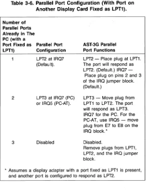
Table 3-6. Parallel Port Configuration (With Port on Another Display Card Fixed as LPT1).
Number of Parallel Ports Already in The PC (with a
Port Fixed as Parallel Port LPT1) Configuration
LPT2 at IRQ? (Default).
AST-3G Parallel Port Functions
LPT2 - Place plug at LPT1.
The port will respond as LPT2. (Default.) IRQ?
-Place plug on pins 2 and 3 of the IRQ jumper block. (Default.)
2
3
LPT3 at IRQ? (PC) or IRQ5 (PC-AT).
Disabled
LPT3 - Move plug from
LPT1 to LPT2. The port will respond as LPT3. IRQ? for the PC. For the
PC-AT, use IRQ5 - move
plug from E? to E8 on the IRQ block.*
Disabled.
Remove plugs from LPT1, LPT2, and the IRQ jumper block.
* Assumes a display adapter with a port fixed as LPT1 is present, and another port is configured to respond as LPT2.
3.5 Installing Your AST-3G
Configuration and Installation
CAUTION
Be sure that the power switch is off and the power cord is removed from the system unit. Turn off any other equipment connected to the computer. Installing any component while the power is on can permanently damage your computer and its components.
You will need a flathead screwdriver or nut driver to perform the following procedure.
STEP 1
Remove the PC cover: Use a flathead screwdriver or nut driver
to remove the cover mounting screws from your PC (see your PC's manual for the location of the cover mounting screws). Once you have removed the cover mounting screws, pull the PC cover off as shown in Figure 3-5.
Figure 3-5. Removing the PC Cover.
For the PC-AT,·unlock the key lock at the front of the PC-AT by
turning the key counterclockwise. Remove the back panel (which is attached to the PC-AT with plastic fastener strips) from the rear of the PC-AT. Use a flathead screwdriver or nut driver to remove the cover mounting screws. Slide the cover toward the front until it comes off, as shown in Figure 3-6.
Configuration and Installation
8
u::::::J
1\1111111111111111111111111111111111111
Figure 3.6. Removing the PC-AT Cover.
STEP 2
Set PC or PC-XT system board Switch Block 1: Locate switch block SW1 on the main circuit board of the PC or PC-XT (the PC-XT has only one system board switch block). Set switches SW1-5 and SW1-6 to ON (on the eight-switch block). Also, check for the correct setting of switch SW1-2. If an 8087 coprocessor is installed, switch SW1-2 must be OFF. Otherwise, it must be ON. Figure 3-7 shows the location of SW1 on the PC and PC-XT.
DO
Configuration and Installation
SW1
"OFF" OPEN
-DODD
"ON" 1 2 3 4 5 6 7 8
Expansion slots
DIP Switch SW1 (PCand PC-Xl)
SW2
DIP Switch SW2
(PConly)
Figure 3-7. Switch Block 1
on
the PC and PC-XT.STEP 3
Install ribbon cable on the ASJ=.3G:This step is necessary only if you intend to use the parallel port. If not, proceed to STEP
4.
Locate the ribbon cable for the parallel port. The parallel port ribbon cable has a rectangular 26-pin connector at one end and a DB25S connector at the other end.
The ribbon cable comes with a bracket. Using the hardware supplied on the D-shell connector, mount the D-shell
connector to the bracket so that when the bracket is installed, the D-shell connector will be accessible at the PC's rear panel. The ribbon cable and bracket for the parallel port are shown in Figure 3-8.
Configuration and Installation
Bracket
1~---DB25S
Connector
Figure 3-8. Parallel Port Ribbon Cable and Bracket.
Plug the parallel adapter cable onto connector P3 on the AS'-:'3G. Plug the cable onto the board so that pin 1 on the rectangular connector (indicated by an arrow and the red or blue stripe on the ribbon cable) aligns with pin 1 on the P3 connector (silkscreened in white on the circuit board). Figure 3-9 shows the parallel port cable installed on the AS'-:'3G.
iilkscreened "1"
Figure 3-9. Installing Ribbon Cable on
Configuration and Installation
STEP 4
Select an open expansion slot:The AS':3G adapter requires one full-length slot. Remove the expansion slot cover and locate the metal cover for the cut-out in the back panel of the PC system chassis for the slot that you have selected.
Remove and save the bracket retaining screw using a small flathead screwdriver. Remove the expansion slot cover. STEP 5
Install the card guide: This step is only necessary in a PC or PC-XT. If you have a PC-AT, go to STEP 6. Install the plastic card guide supplied with the AS':3G (if one is not already installed) on the inside front panel of the PC for the slot that will hold your AS':3G adapter (Figure 3-10).
Card guide
(Note that "fingers" point down)
-=-=
-=.".~-~
~~:
~
'IL--
Front panel.1
..
~"I
~
L
"!II
, ~ .11
----~ ~."~~JI"
~
---.:T
Figure 3-10. "Installing the Plastic Card Guide.
STEP 6
Install the AST-3G adapter: Line up the AS':3G adapter and position its front bottom corner in the card guide channel. Position any wires or ribbon cables so they will pass either beneath or above the installed card and will not be damaged during installation. Lower the board until its edge connector is resting on the expansion slot receptacle. Using an evenly distributed pressure,>press the AS':3G adapter straight down
until it seats in the expansion slot (Figure 3-11).
Configuration and Installation
~--AST·3G
Model 1
Figure 3-11. Installing the ASJ:.3G Adapter.
STEP 7
Secure the card to the rear of the PC system chassis: Use the screw you removed from the expansion slot cover in STEP 5. STEP 8
Replace PC cover: Carefully slide the cover from the front until it stops securely against the rear panel. Reinstall the cover mounting screws you removed earlier.
For the PC-AT, slide the cover from the front until it stops securely against the rear panel, reinstall the cover mounting screws, and press the back panel so that the plastic fastener strips secure it in place.
STEP 9
Install Cables: Replace the power cord to the system unit and be sure that the keyboard and the monitor connectors are plugged in. Reattach any other cables (including the printer cable to your new printer port), and connectors you removed previously.
STEP 10
Configuration and Installation
STEP 11
Now you are ready to power up: On the PC-AT, run the SETUP .program.·lnstead of setting hardware switches on the main system board for the PC-AT, you will need to run the SETUP program provided on the IBM PC-AT Diagnostics diskette. SETUP is a menu-driven program that allows you to configure your PC-AT for the type of graphics card you will be using. Check your PC-AT Guide to Operations manual for full instructions on using SETUR
SECTION 4
PARALLEL PORT
The parallel ports in the PC provide one-way communication (output only) between the PC and parallel peripheral devices such as printers or plotters. Data is sent from the PC to the external device eight bits (one byte) at a time. A PC running under DOS will support up to three parallel ports. These ports are referred to as LPT1, LPT2, and LPT3 (some IBM manuals also call the default port "PRN").These are the only parallel ports DOS can access.
The AS1=-3G Model 1 graphics display adapter can be equipped with one parallel port as an optional feature
(available at the time of purchase or by means of the Parallel Port Enhancement Kit). When the PC is also equipped with a display card that has a parallel port fixed as LPT1, the AS1=-3G parallel port can respond as LPT2 or LPT3. Otherwise, the AS1=-3G parallel port can respond only as LPT1 or LPT2 (refer to Section 3.4).
4.1 I/O Address and Interrupt Assignments
Parallel Port
Table 4-1. PC Parallel Port I/O & IRQ Assignments (With Port on Another Display Card Fixed as LPT1).
AST-3G Switch
Setting Port I/O Address IRQ Line used Port Location
N/A LPT1 3BC-3BE Hex IRQ?
LPT1 LPT2 378-3?A Hex IRQ5 or IRQ7* * LPT2 LPT3 278-2?A Hex Not Supported* * Interrupt-driven I/O for LPT3 is not supported in the PC. ** IRQ5 on the PC-AT, IRQ? on PC or PC-XT.
Display Card AS"f..3G AS"f..3G
Table 4-2. PC Parallel Port I/O & IRQ Assignments (Without Port on Another Display Card Fixed as LPT1).
AST-3G Port&
Switch
Setting I/O Address IRQ Line Used Port Location
LPT1 LPT2 LPT3
3?8-37A Hex IRQ7
2?8-27A Hex IRQ5 or IRQ?*
~ LPT3 Not Supported ~
AST-3G AST-3G
*IRQ5 on the PC-AT, IRQ? on the PC or PC-XT.
The AST-3G Model 1 conforms to these standards and uses identical I/O and IRQ assignments.
4.2 Parallel Port Pinout Specifications
The parallel ports in the PC and on the AST-3G use a DB25S (socket) interface connector. The pinouts for all the parallel ports are identical and are shown in Table 4-3.
Parallel Port
Table 4-3. DB25S Parallel Port Pinouts.
Line Name -STROBE 00 01 D2 D3 04 05 06 07 -ACK BUSY PE SLCT -AUTOFO -ERROR -INIT -SLCT IN GROUNO
AST Adapter Cable Output DB25S 1 2 3 4 5 6 7 8 9 10 11 12 13 14 15 16 17 (18-24)
IBM Matrix Printer Centronics Interface 1 2 3 4 5 6 7 8 9 10 11 12 13 14 32 31 36 (16,19-30,33)
4.3 Configuring External Parallel Devices
Whenever you connect a new device to your computer such as a parallel printer, you may also have to perform a one-time configuration of that device to establish desired operating parameters. This is usually done by setting switches in the device. Refer to the installation manual supplied with the device for further information on its configuration
requirements.
4.4 Programming the Parallel Port
Normally no special action is necessary to prepare the parallel ports for use. However, you can use the DOS MODE
Parallel Port
4.5 Interrupt-Driven Parallel Printer Software
Interrupt-driven parallel printer software uses IRQ7. To ensure that your interrupt-driven parallel printer software operates correctly, you must leave IRQ7 enabled on the AST-3G (the default), by leaving a shorting plug on jumper E7. It will not harm anything to leave IRQ7 enabled even if you do not run interrupt-driven software for your parallel printer.
4.6 Parallel Port Diagnostic Testing
The parallel port on your AS':3G is completely compatible with the IBM Diagnostics software. However, you must configure the parallel port as LPT1 so that the port can be recognized by the diagnostics.
If you run the matrix printer test, your printer must be 100% compatible with an Epson MX-80™ or errors can be generated.
SECTION 5
DIAGNOSTICS
A diagnostics program is provided with your AS':3G Model 1 graphics display adapter. This program allows you to check the current configuration of your AS':3G adapter, and ·to determine if all the graphics capabilities of your AS':3G are working as they should be.
The diagnostics· program is a series of screens to test the different graphics capabilities of the AS':3G. There are three sets of screens that will be presented, depending on whether you have a Monochrome Display (MD), a Color Display (CD), or an Enhanced Color Display (ECD) attached to the AS':3G. After an initial configuration screen, each screen presented will test a particular aspect of the AS':3G's capabilities. At the bottom of each screen is a prompt telling you how to proceed to the next step. Generally, you will need to press the ...-J key « ~nter
>
key) to proceed to the next screen or test, or<
Esc> to quit the program.Ifa labeled region on one of the test screens displays a different color or mode from its label, then proceed through the following steps:
• If two areas labeled with different intensities appear the same, adjust the brightness and contrast controls to see if this increases intensity differences.
Diagnostics
5.1 Starting the Diagnostics Program
To initiate the Diagnostics program, type in the following command at the DOS prompt:
A<DIAG
<
Enter>After this command is entered, the diagnostics program will present either an error message indicating that no AST:3G Model 1 card is present, or a configuration screen listing the basic configuration of the AS'-:'3G display adapter.
5.2 The Configuration Screen
For all AS':3G Model 1 configurations, the diagnostics program presents as its first screen a configuration screen that allows you to check whether your AST:3G Model 1 is configured properly. A sample configuration screen for a monochrome monitor and the AS':3G Model 1 .adapter follows:
AST-3G ADAPTER DIAGNOSTICS, VERSION 1.0 AST RESEARCH, INC. 1986
Display attached to AST-3G is MONOCHROME Switches 1 through 4, on the board are set to OFF OFF ON OFF Available on board memory is 256K System board BIOS date is 10127/82
Press<ESC> if the monitor type is incorrect,..-J to proceed
Diagnostics
Display Type
The choices for the Display type are MONOCHROME, COLOR, and ENHANCED (corresponding to the MD, CD, or ECD monitor). If the vallie shown is not accurate, then your SW1 switch settings probably are wrong. Table 3-2 shows all the SW1 switch settings and their
corresponding configurations. SW1 Switch Settings
The values shown for Switches 1 through 4 should display how the SW1 switches are set. If they are not set correctly for the configuration you wish, then exit the program and change your switch settings (the SW1 switch is accessible at the back of your PC system). Memory on AS7=-3G Model 1 Graphics Display Adapter
Available on-board memory displays the amount of memory available on the AS1=-3G Model 1. This should be either 64 KB or 256 KB.
ROM BIOS date
The mother board BIOS date shows the date of the ROM module in your PC system. If this date is earlier than 10/27/82, then you need to have the new ROM BIOS installed in your PC system. The date will be displayed even if the AS1=-3G is not .present in the system. Thus you can check the BIOS date before you install the AS1=-3G.
5.3 The Test Screens
Three sets of diagnostics tests are provided with AS1=-3G. One set is used for each type of monitor-the Monochrome Display (MD), the Color Display (CD), and the Enhanced Color Display (ECD). In the following sections, a description of each test is given, followed by a sample screen. If the. screen is
Diagnostics
5.3.1 Monochrome Display Tests M1 - Monochrome Display Test
Sixteen background text attributes and sixteen foreground text attributes are shown in labeled rectangles. Each rectangle tests a different attribute, although some are labeled the same. Some attributes can be displayed in intensified or blinking. To switch between the two, press the
<
SPACE> bar.TEST M1: TEXT ATTRIBUTES
BACKGROUND SHADES (Black text) Black Normal Normal Normal Normal Normal Normal Normal Black Blinking Blinking Blinking Blinking Blinking Blinking Blinking TEXT SHADES (Black background) Black Normal Underlined Normal Normal Normal Normal Normal Normal Black Intensified Underlined Intensified Intensified Intensified Intensified Intensified Intensified
Press ~ for next test, <ESC> to qUit, <SPACE> to toggle blink/intensify
Figure 5-2. Monochrome· Text Attributes Test (Blinking).
Diagnostics
TEST M1: TEXT ATTRIBUTES
BACKGROUND SHADES (Black text)
Black Normal Normal Normal Normal Normal Normal Normal Black Intensified Intensified Intensified Intensified Intensified Intensified Intensified
TEXT SHADES (Black background)
Black Normal Underlined
Normal Normal Normal Normal Normal Normal Black Intensified Underlined
Intensified Intensified Intensified Intensified Intensified Intensified
Press~ for next test, <ESC> to quit, <SPACE> to toggle blink/intensify
Figure 5-3. Monochrome TextAttributes Test
Diagnostics
M2 and M3 - Monochrome Character Set Tests
These two screens show the character set available with either 9 x 14 pixel or 8 x 8 pixel characters. The characters should show up clearly.
TEST M2: 9x14 CHARACTER SET
Press...J for next test, <ESC> to quit
Figure 5-4. Monochrome Character Set Test
(9 x 14 pixel character box).
Diagnostics
TEST M3: 8x8 CHARACTER SET
Press...J for next test, < Esc> to qUit
Figure 5-5. Monochrome Character Set Test
Diagnostics
M4 - Paged Memory Display Test
This screen shows the pages of memory available in your PC. There should be four pages available if you have· 64 KB of memory, and eight pages if you have 256 KB of memory. You can traverse through the pages by pressing the space bar. The backgrqund of the screen is made up of the number of the page, from 1 to 8.
TEST M4: DISPLAY 8 MEMORY PAGES
888888888888888888888888888888R8888888888888R888888888888888 888888888888888888888888888888888888888888888888888888888888 8888888888888888R88888888888888888888888888888888888888888R8 888888888888888888888888888888888888888888888888888888888888 8888888888888888888888888888888888888888888888888888888RR888 888888888888888888888888888888888888888888888888888888888888 88888888888888888888888888888888888888888888888888888888888R
8888~8888888888888888888888888888A88888888888888888888888888
888888888888888888888888888888888888888888888888888888888888
8888888888888888888888888 PAGE 8 8888888888888888888F$888Afl
88888888888888888888888888888R88888888888888888888888888R88R 888888888888888888888888888888888888888888888888888888888888 88888888888888888888888888888888888888888888888888888888RR8i3 888888888888888888888888888888888888888888888888888888888888 8888888888888888888888888888888888888888888888888888888888R8 888888888888888888888888888888888888888888888888888888888888 88AARA8R8R88R888888888A88888R8R8888888888R88R888A88888888888 8888888888888888888888888888888888888888888888888888888888R8 888888888888888888888R888888888888888888888888888888888A88R8
Press ~ for next test,<ESC> to quit, <SPACE> to see next page.
Figure 5-6. Monochrome Memory Pages Test.
Diagnostics
M5 - 640 X350 Resolution Monochrome Graphics Intensity Test
This screen shows four different intensities available for graphics with an ASr-3G, black, normal, intensified, or blinking. If normal and intensified appear the same, adjust the contrast on your monitor. The intensities should all appear different.
TEST M5: 640x 350 GRAPHICS, 4 INTENSITIES
Black Normal
_.~
/' I I I 1\'Intensified Blinking
Press ~ for next test,<ESC> to quit.
Diagnostics
5.3.2 Color Display Tests
If you are using a CD monitor, you will be presented with a set of tests designed for this configuration, as follows.
C1 -
Text Attributes TestThis screen displays text and background using 16 different colors. Each field is labeled with the name of the color that is· meant to appear there. The sixteen text colors are shown on the right, using colored letters against a black background. On the left, the 16 colors are shown and are labeled with black letters. The second half of the background colors can be either intensified or blinking. To switch between the two, ·press the
<
SPACE> bar.TEST C1: TEXT ATIRIBUTES
BACKGROUND COLORS (Black text) Black Blue Green Cyan Red Magenta Brown Gray Black Blinking Blue Blinking Green Blinking Cyan Blinking Red Blinking Magenta Blinking Brown Blinking Gray TEXT COLORS (Black background) Black Blue Green Cyan Red Magenta Brown Gray Dark Gray Light Blue Light Green Light Cyan Light Red Light Magenta Yellow White
Press ~ for next test, <ESC> to qUit, <SPACE> to toggle blink/intensify
Figure 5-8. Color·TextAttributes Test (Blinking).
Diagnostics
TEST C1: TEXT ATTRIBUTES
BACKGROUND COLORS (Black text)
Black Blue Green
Cyan Red Magenta
Brown Gray Dark Gray Light Blue Light Green
Light Cyan Light Red Light Magenta
Yellow White
TEXT COLORS (Black background)
Black Blue Green
Cyan Red Magenta
Brown Gray Dark Gray Light Blue Light Green
Light Cyan Light Red Light Magenta
Yellow White
Press~_J for next test, < Esc> to quit, <SPACE> to toggle blink/intensify
Diagnostics
C2 and C3 - Color Character Set Tests
These two screens display the available character set; C2 shows the characters 'in a 40-column wide screen, and C3 shows them in an aO-column wide screen.
TEST C2: 8x8 CHARACTER SET, 40 COLUMNS
press...J for next test, <Esc> to quit
Figure 5-10. Color Character Set Test, 40-Column. Wide Format.
TEST C3: 8x8 CHARACTER SET, 80 COLUMNS
Press ~,for next test,< Esc> to quit
Figure 5-11. Color Character Set Test,
80-Column Wide Format.
Diagnos~ics
C4 - Display Memory Pages Test
This screen shows the pages of memory available in your PC. There should be four pages when 64 KB are available, and eight pages when 256 KB are available. You can traverse through the pages by pressing the space bar. The background of the screen is made up of the number of the page, from 1 to 8.
TEST C4: DISPLAY 8 MEMORY PAGES
111111111111111111111111111111111111111111111111111111111111
1 1 11 1 1 1 1 1 11 11 1 1 11 11 1 1 1 1 1 1 l 1 l 1 1j.III 1:I.III 1 1 1 111. 1.1:I.1 11 1 1 1 1.1.:I.1 1:I
111111111111111111111111111:1.11111111111111111111111111111111 1111:I.1 1 1 11 1. 11 1 1:I.1 1 1 1 11 1:I.1 1 1:I1 1. 1:I.11 1 11 11.:I.:t.1.1:I.1 1:I.11 111 1 1 1:I. :I.1.1:t.
111111111111111111111111111111111111111111111111111111111111 1111111:1.11111111111:1.111111111111111111111111:1.111111111111111 111111111111111111111111111111111111111111111111111111111111 111111111:1.:1.11:1.111111111111111111111111111:1111111111111111111 1111111111111111111111111111111111111111111111111111111111:1.1
11 1 1 1:I.J.:I.1 1 1 11 1:I.1 11.:I.1 1 1 1 1 1 PAGE 1 :I.:1.1:I.11:I.11.1.1.1. 1 11 1 1:I.1 11.1. 1.:I.1
111111111111111111111111111111111111111111111111111111111111
11111111:1.11111111111111111111:1.:1.111111111.1111111111.l11:l. 11:1.1.11
111111111111111111111111111111111111111111111111111111111111
111111111:1.1:I.111111111111111:I.1:I11. 11.1. 1:1. 111. 1:I.1. 111. 1.11:I.11.1 111:I.111
111111111111111111111111111111111111111111111111111111111111
1.11.11 1. 111.1 1 11:l.1 1 11:I.11:I.11 1 1:I.1.1.:I.1 1:I.1:I.1.:I.l 1 1 1 1:I.11.1 11.1 l 11.1 1:It1.:Ij:I
111111111111111111111111111111111111111111111111111111111111
1 1 1 l 11:J.11:J.1 11 1 11 11:I.111111 1 1:I.111. 11 11:J.1.1 1:J.111 11:I. ,.1 1 1 1 1:I. :J.1.1 1:J.1.:J.
1111111111111111111111111111111111111111111111:1.1111111111111
Press
~
for next test,<Esc> to quit,<SPACE> to see next pageFigure 5-12. Color Memory Pages Test.
Diagnostics
C5 - 320 X200 Resolution Graphics, 4 Colors
This screen shows the four basic color components that provide the colors for this configuration: black, blue, green, and red. These colors are shown in 4 rectangular boxes. The colors of the boxes should match their labels.
TEST C5: 320x 200 GRAPHICS, 4 COLORS
11111111
Black Blue Green Red
Press..-J for next test,< Esc >to quit
···Diagnostics
C6 - 640
x
200 Resolution Graphics, 2 ColorsThis screen displays the colors black and white in rectangular boxes. The colors of the boxes should match their labels.
TEST C6: 640 x200 GRAPHICS, 2 COLORS
II
Black
D
White
Press ~ for next test, < Esc> to quit
Figure 5-14. Color 640x2002-Color Graphics.
Diagnostics
5.3.3 Enhanced Color Display Tests
If you are using an ECD monitor, you will be presented with a set of tests designed fo~ this configuration, as follows:
E1 - Text Attribute Tests
This screen displays text and background using 16 different colors. Each field is labeled with the name of the color that is meant to appear there. The sixteen text colors are shown on the right, using colored letters against a black background. On the left, the 16 colors are shown and are labeled with black letters. The second half of the background colors can be either intensified or blinking. To switch between the two, press the
<
SPACE> bar.TESTE1: TEXT ATTRIBUTES
BACKGROUND COLORS (Black text) Black Blue Green Cyan Red Magenta Brown Gray Black Blinking Blue Blinking Green Blinking Cyan Blinking Red Blinking Magenta Blinking Brown Blinking Gray TEXT COLORS (Black background) Black Blue Green Cyan Red Magenta Brown Gray Dark Gray Light Blue Light Green Light Cyan Light Red Light Magenta Yellow White
Press
~
for next test, <ESC> to quit, <SPACE> to toggle blink/intensifyDiagnostics
TESTE1: TEXT ATTRIBUTES
BACKGROUND COLORS (Black text)
Black Blue Green
Cyan Red Magenta
Brown Gray Dark Gray Light Blue Light Green
Light Cyan Light Red Light Magenta
Yellow White
TEXT COLORS (Black background)
Black Blue Green
Cyan Red Magenta
Brown Gray Dark Gray Light Blue Light Green
Light Cyan Light Red Light Magenta
Yellow White
Press~ for next test,< Esc> to quit, < SPACE> to toggle blink/intensify
Figure 5-16. Enhanced TextAttributes Test
(Intensified)
Diagnostics '
E2, E3, E4 - Enhanced Color Character Set Tests
These three screens display the available character set; E2 shows the characters in an a x a pixel matrix in 40-column mode; E3 shows them in an
a x 14 pixel matrix in aD-column mode; and E4 shows them in a x a pixel matrix in aD-column mode with 43 lines.
TEST E2: 8 x 8 CHARACTER SET, 40 COLUMNS
Press
~
for next test,< Esc> to quitFigure 5-17. Enhanced Character Set Test (8 x 8pixel
DiagnQstics
TEST E3: 8x14 CHARACTER SET, 80 COLUMNS
Press
....J
for next test, <Esc> to quitFigure 5-18. Enhanced Character Set Test (8 x 14
pixel characters, 80columns).
Diagnostics
TEST E4: 8x8 CHARACTER SET, 43 ROWS
Press
~
for next test, <Esc> ·to quitFigure 5-19. Enhanced Character Set Test (8 x 8
Diagnostics
£5 - Display Memory Pages Test
This screen shows the pages of memory available in your PC. There should be four pages when 64 KB are available, and eight pages when 256 KB are available. You can traverse through the pages by pressing the space bar. The background of the screen is made up of the number of the page, from 1 to 8.
TEST C4: DISPLAY 8 MEMORY PAGES
111111111111111111111111111111111111111111111111111111111111 111111111111111111111111111:1.1111111111111111111111111111:1.111 111111111111111111111111111111111111111111111111111111111111 111111111111111:1.1111111:1.111111111111111111.11.1111111111111111 111111111111111111111111111111111111111111111111111111111111 111111111111111111111111111111111111111111111111111111111111 111111111111111111111111111111111111111111111111111111111111 111111111111111111111111111111111111111111111111111111111111 1111111111111111111111111.11111111111111111111111111111111111
1.1 1 1 1. 1 1. 1 1 1 1 1 1 1 1 1 1 1 11.1 1 1 1.1. PAGE 1 1 11.1.1.:I.1.1 1. 1 1. 1 1. 1 1 1 1 11.1 1. 1 1 J 1 111111111111111111111111111111111111111111111111111111111111 11.1.11.1111.1111111111111111111.1.1.1111.111111.11.111111111111.111111 111111111111111111111111111111111111111111111111111111111111 111111111.1111111111111111111111111.1.1111.1.11.11111.111.11.11111111 111111111111111111111111111111111111111111111111111111111111 111.1.1.1.1111.111111111111111.11.11.1111111.111111.111.1111:1.1111.111111 111111111111111111111111111111111111111111111111111111111111 1111111111111111111111111111111.11111.111111111111111111111111 111111111111111111111111111111111111111111111111111111111111
[image:63.394.26.312.163.429.2]Press
~
for next test,<Esc> to quit, <SPACE> to see next pageFigure 5-20. Enhanced Memory Pages Test.
Diagnostics
E6 - 320X 200 Resolution Graphics, 4 Colors
This screen shows the four basic color components that provide the colors for this configuration: black, blue, green, and red. These colors are shown in 4 rectangular boxes. The colors should match their labels.
TEST E6: 320x200 GRAPHICS, 4 COLORS
11111111
Black Blue Green Red
Press·~ for next test, <Esc> to quit
Diagnostics
E7 - 640X200 Resolution Graphics, 2 Colors
This screen displays the colors black and white in rectangular boxes. The colors of the boxes should match their labels.
TEST E7: 640x200 GRAPHICS, 2 COLORS
II
Black
D
White
Press...-J for next test, <Esc> to quit
Figure 5-22. Enhanced 640x200 2-Color Graphics Test.
Diagnostics
E8 - 640 X350 Resolution Graphics, Primary Colors This screen shows four intensities of four different colors - blue, green, red and gray, providing a total of 16 boxes. Except for the first column, each box should appear slightly different. If the last two red boxes are the same, even after your contrast and brightness controls are checked, then the Monitor Selection jumper may be set wrong.
TEST E8: 640x350 GRAPHICS, PRIMARY COLORS
BLUE
•
SHADESGREEN
•
SHADESRED
•
SHADESGRAY
•
SHADES••
••
••
••
Press~
for next test, <Esc> to quit5-26
SECTION 6
PRODUCT REPAIR PROCEDURE
If your AST Research product ever requires repair, contact your dealer first. The dealer from whom you originally
purchased the product can usually service the product. If you must return a hardware product to the factory for service, follow these guidelines to ensure rapid, accurate turnaround:
1. Call AST Research Technical Support for
a
Return Authorization Number (RAN): A technician will discuss the problem with you; if factory service is required, the technician will give you a Return Authorization Number (RAN). Always refer to the RAN when you return anything for service. AST Research will return anything without a RAN to the sender.2. If the product is covered under an AST Research Warranty: There is no charge for parts or labor involved in the repair. Please include a copy of your original purchase receipt as the proof of date of purchase for all warranty repairs.
3. If the product is not covered under
a
warranty: Contact your dealer or AST Research Technical Support for instructions on obtaining service for your product.Product Repair Procedure
unless you specifically authorize us to do so in writing when you send the board to us. The parts charges and any applicable labor charges will be billed COD.
5. Describe the problem and return any related accessories: Please include a brief but explicit written description of the problem when you return your AST product to the factory for repair. Also return any accessories that might relate to the problem. For example, if the the parallel port does not function correctly, be sure to return the parallel port adapter cable with the board.
6. Besure to provide a return shipping address that UPS can deliver to and include your RAN: UPS cannot normally deliver to post office boxes.
Reference the RAN issued to you by AST Technical Support on all correspondence. Securely package all materials to prevent shipping damage. Shipping charges must be prepaid; COOs will not be accepted. Ship the materials to the following address:
AST Research, Inc.
Customer Service-RAN xxxx 2722 Michelson
Irvine, CA 92715
where xxxx is your assigned Return Authorization Number.
7. Once your product is repaired, we will return it to you by UPS or UPS Blue Label service, whichever is appropriate for your geographical location. We will return items covered by warranty at our expense. Shipping costs and repair expenses for items not covered by warranty will be billed COD. If you prefer overnight service (UPS Red Label), the shipping charges will be billed COD. If you want us to ship Federal Express, please give us your Federal Express account number for billing purposes.
SECTION 7
ENHANCEMENT OPTIONS
This section tells you how to install the following options: • Section 7.1 tells you how to install the memory
upgrade kit (part number 500305-006).
• Section 7.2 tells you how to install the parallel port upgrade kit (part number 500305-005).
The memory upgrade kit allows you to upgrade your AS1=-3G adapter memory from 64 to 256 Kilobytes (KB) by substituting eight 256-Kilobit (Kb) chips for the eight 64-Kb chips on your AS1=-3Gboard. The parallel port upgrade kit allows you to add a parallel port to your AS1=-3G by adding six chips and a parallel port ribbon cable and bracket to your AS1=-3G.
7.1 Installing the Memory Upgrade Kit
Following are instructions for replacing the eight 64-Kb chips on your AS1=-3G adapter with 256-Kb chips.
STEP 1
Check that you have eight chips in your memory upgrade kit.
You will need a flathead screwdriver or nut driver to remove the PC system cover and install the memory chips. (You· can also use a chip puller to remove the existing memory chips.) STEP 2
Enhancement Options
STEP 3
Remove ribbon cable if present: This step only applies if you already have a parallel port installed on your AS1=-3G. Remove the parallel port ribbon cable connected to the AS1=-3G. Be sure to note its orientation for later reference when you rei nstall it.
STEP. 4
Remove ASJ=.3G from your PC: Use a nut dri.ver or a flathead screwdriver to remove the screw that secures the AS1=-3G bracket to the back of the PC chassis. Keeping the adapter level and using even pressure, remove the board from the PC system chassis.
Memory Upsrade Chips
Install 74LS374
6J
~d~ ~rtR,,,
"rf?;
=~
~r.:O
U
n
TI
~
0
DuEO~,~.~~
~~O D~ ~=D~'n:
""
D.
~
U.:
I· t IIns a =....:,.'....'..'<", c3c3
0
7~~:~:O
I
Ul'~·
0_
Q
6 ""~.4LS244
----M
1w
.~.'::.:::
....,::.:'.':.".'...•.:..',.'....•...
i.:.m ..•.
:.~'.~
.•.••.••:.;,•.••i.•.'.,.·.•.,.i.~.?
..•.•.'~
( ), 'fil5i i
7~Ls~~~4
I:
':,,~.~~ ;:.o;:.oil~'
_ _-==-Install
----+a
l
li.:.•.':.~.;.:.~.'
.•.~.E.,
•..,.,:,::.•••..<In ..n '''''''''''n """'.,n"""',~
'-"-L",-_-Replace current chips74LS138~ m with 8 upgrade chips
Install
I
nl,,·
8'"74LS05 .
~
I,li
D~
0
I.~()
tj j.i~~~60 c:::J .
-~6 r:!!::J..n ~ LJ~
~o~ O~
0"
tod . , '0" D.
~
TI. TI"
Parallel Port Upgrade Chips
Figure 7-1. ASJ:.3G Adapter Upgrade Chip Placement.
Enhancement Options
STEP 5
) Remove the eight 64-Kb chips from the ASJ=.3G: Remove the 64-Kb chips from the AS1=-3G by prying them loose with a screwdriver. Do not damage the chip pins so you can use them in the future. The position of the memory chips is shown in Figure 7-1.
STEP 6
Install the eight 256-Kb chips: Follow these guidelines for installing chips:
• Before handling any chips, discharge any static electricity on your body by touching a grounded surface such as the PC chassis.
• Chips mustbe properly oriented when you install them. The notch on each chip should be facing away from the AS':3G bracket. Also, any numbers printed on the chip should be facing right-side up when the board is held with the bracket on the right (the same as the other labeled components on the adapter).
• If a chip seems to be too wide to fit its socket, place it on its side on a flat surface and gentlyangle it under both thumbs to slightly bend the legs inward. This technique can also be useful for inserting a chip into a socket on the board. Angle the chip, and slightly insert one row of pins, then bring the other row down into position and slightly start its pins in the socket. Once you have both sides started, you can evenly press down on the chip to seat it firmly in its socket.
STEP 7