The RenderMan Interface
Version 3.2.1
Copyright c2005 Pixar. All rights reserved.
No part of this publication may be reproduced, stored in a retrieval system, or transmitted, in any form or by any means, electronic, mechanical, photocopying, recording, or other-wise, without the prior permission of Pixar.
The information in this publication is furnished for informational use only, is subject to change without notice, and should not be construed as a commitment by Pixar. Pixar assumes no responsibility or liability for any errors or inaccuracies that may appear in this publication.
TABLE OF CONTENTS
List of Figures vii
List of Tables viii
Preface x
Part I
The RenderMan Interface
1
Section 1 INTRODUCTION 2
1.1 Features and Capabilities . . . 4
1.1.1 Required features . . . 4
1.1.2 Advanced Capabilities . . . 5
1.2 Structure of this Document . . . 6
Section 2 LANGUAGE BINDING SUMMARY 7 2.1 C Binding . . . 7
2.2 Bytestream Protocol . . . 10
2.3 Additional Information . . . 11
Section 3 RELATIONSHIP TO THE RENDERMAN SHADING LANGUAGE 12 Section 4 GRAPHICS STATE 15 4.1 Options . . . 19
4.1.1 Camera . . . 19
4.1.2 Displays . . . 28
4.1.3 Additional options . . . 34
4.1.4 Implementation-specific options . . . 36
4.2 Attributes . . . 37
4.2.1 Color and opacity . . . 38
4.2.2 Texture coordinates . . . 40
4.2.3 Light sources . . . 41
4.2.4 Surface shading . . . 44
4.2.5 Displacement shading . . . 46
4.2.6 Volume shading . . . 46
4.2.7 Shading rate . . . 48
4.2.8 Shading interpolation . . . 49
4.2.9 Matte objects . . . 49
4.2.11 Detail . . . 51
4.2.12 Geometric approximation . . . 53
4.2.13 Orientation and sides . . . 53
4.3 Transformations . . . 55
4.3.1 Named coordinate systems . . . 58
4.3.2 Transformation stack . . . 60
4.4 Implementation-specific Attributes . . . 60
Section 5 GEOMETRIC PRIMITIVES 62 5.1 Polygons . . . 63
5.2 Patches . . . 68
5.3 Subdivision Surfaces . . . 75
5.4 Quadrics . . . 77
5.5 Point and Curve Primitives . . . 83
5.6 Blobby Implicit Surfaces . . . 85
5.7 Procedural Primitives . . . 87
5.8 Implementation-specific Geometric Primitives . . . 92
5.9 Solids and Spatial Set Operations . . . 92
5.10 Retained Geometry . . . 94
Section 6 MOTION 96 Section 7 EXTERNAL RESOURCES 99 7.1 Texture Map Utilities . . . 99
7.1.1 Making texture maps . . . 99
7.1.2 Making environment maps . . . 100
7.1.3 Making shadow maps . . . 102
7.2 Errors . . . 103
7.3 Archive Files . . . 104
Part II
The RenderMan Shading Language
106
Section 8 INTRODUCTION TO THE SHADING LANGUAGE 107 Section 9 OVERVIEW OF THE SHADING PROCESS 109 Section 10 RELATIONSHIP TO THE RENDERMAN INTERFACE 112 Section 11 TYPES 114 11.1 Floats . . . 11411.2 Colors . . . 114
11.3 Points, Vectors, and Normals . . . 115
11.4 Transformation Matrices . . . 116
11.5 Strings . . . 117
11.6 Arrays . . . 117
11.7 Uniform and Varying Variables . . . 118
12.1 Surface Shaders . . . 119
12.2 Light Source Shaders . . . 120
12.3 Volume Shaders . . . 122
12.4 Displacement Shaders . . . 122
12.5 Imager Shaders . . . 122
Section 13 LANGUAGE CONSTRUCTS 125 13.1 Expressions . . . 125
13.2 Standard Control Flow Constructs . . . 125
13.3 Illuminance and Illuminate Statements . . . 127
Section 14 SHADERS AND FUNCTIONS 129 14.1 Shaders . . . 129
14.2 Functions . . . 131
Section 15 BUILT-IN FUNCTIONS 133 15.1 Mathematical Functions . . . 133
15.2 Geometric Functions . . . 137
15.3 Color Functions . . . 140
15.4 Matrix Functions . . . 140
15.5 String Functions . . . 141
15.6 Shading and Lighting Functions . . . 141
15.7 Texture Mapping Functions . . . 143
15.7.1 Basic texture maps . . . 145
15.7.2 Environment maps . . . 145
15.7.3 Shadow depth maps . . . 146
15.7.4 Getting Information About Texture Maps . . . 146
15.8 Message Passing and Information Functions . . . 146
Section 16 EXAMPLE SHADERS 151 16.1 Surface Shaders . . . 151
16.1.1 Turbulence . . . 151
16.1.2 Ray tracer . . . 152
16.2 Light Sources . . . 152
16.3 Volume Shader . . . 153
16.4 Displacement Shaders . . . 154
16.5 Imager Shaders . . . 154
Section A STANDARD RENDERMAN INTERFACE SHADERS 155 A.1 Null Shader . . . 155
A.2 Surface Shaders . . . 155
A.2.1 Constant surface . . . 155
A.2.2 Matte surface . . . 155
A.2.3 Metal surface . . . 156
A.2.4 Shiny metal surface . . . 156
A.2.5 Plastic surface . . . 156
A.2.6 Painted plastic surface . . . 157
A.3 Light Source Shaders . . . 157
A.3.2 Distant light source . . . 157
A.3.3 Point light source . . . 158
A.3.4 Spotlight source . . . 158
A.4 Volume Shaders . . . 159
A.4.1 Depth cue shader . . . 159
A.4.2 Fog shader . . . 159
A.5 Displacement Shaders . . . 159
A.5.1 Bumpy shader . . . 159
A.6 Imager Shaders . . . 160
A.6.1 Background shader . . . 160
Section B RENDERMAN SHADING LANGUAGE SYNTAX SUMMARY 161 B.1 Declarations . . . 161
B.2 Statements . . . 162
B.3 Expressions . . . 163
B.4 Preprocessor . . . 166
Section C LANGUAGE BINDING DETAILS 167 C.1 ANSI C Binding . . . 167
C.2 RIB Binding . . . 175
C.2.1 Syntax rules . . . 175
C.2.2 Error handling . . . 180
Section D RENDERMAN INTERFACE BYTESTREAM CONVENTIONS 185 D.1 RIB File Structuring Conventions . . . 185
D.1.1 Conforming files . . . 185
D.1.2 RIB File structure conventions . . . 186
D.1.3 Conventions for structural hints . . . 188
D.1.4 RIB File structuring example . . . 190
D.2 RIB Entity Files . . . 191
D.2.1 RIB Entity File example . . . 192
D.3 RenderMan Renderer Resource Files . . . 192
D.3.1 Format of Renderer Resource Files . . . 192
D.3.2 Renderer Resource File example . . . 193
Section E STANDARD BUILT-IN FILTERS 195 E.1 Box Filter . . . 195
E.2 Triangle Filter . . . 195
E.3 CatmullRom Filter . . . 195
E.4 Gaussian Filter . . . 196
E.5 Sinc Filter . . . 196
Section F STANDARD BASIS MATRICES 197 Section G RENDERMAN INTERFACE QUICK REFERENCE 198 G.1 Interface Routines . . . 198
Section I DIFFERENCES BETWEEN VERSION 3.2.1 AND 3.1 211 Section J STATEMENT ABOUT PIXAR’S COPYRIGHT AND TRADEMARK RIGHTS
LIST OF FIGURES
4.1 Camera-to-Raster Projection Geometry . . . 22
4.2 Imaging pipeline . . . 31
5.1 Bicubic patch vertex ordering . . . 70
5.2 Patch Meshes . . . 72
5.3 Quadric Surface Primitives . . . 81
5.4 Quadric Surface Primitives (continued) . . . 82
9.1 The ray tracing paradigm . . . 110
9.2 Shader evaluation pipeline . . . 111
12.1 Surface shader state . . . 120
12.2 Light Source Shader State . . . 122
LIST OF TABLES
4.1 Camera Options . . . 20
4.2 Point Coordinate Systems . . . 21
4.3 Display Options . . . 29
4.4 Additional Options . . . 34
4.5 Typical implementation-specific options . . . 37
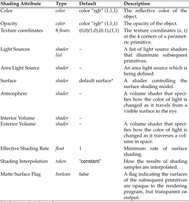
4.6 Shading Attributes . . . 39
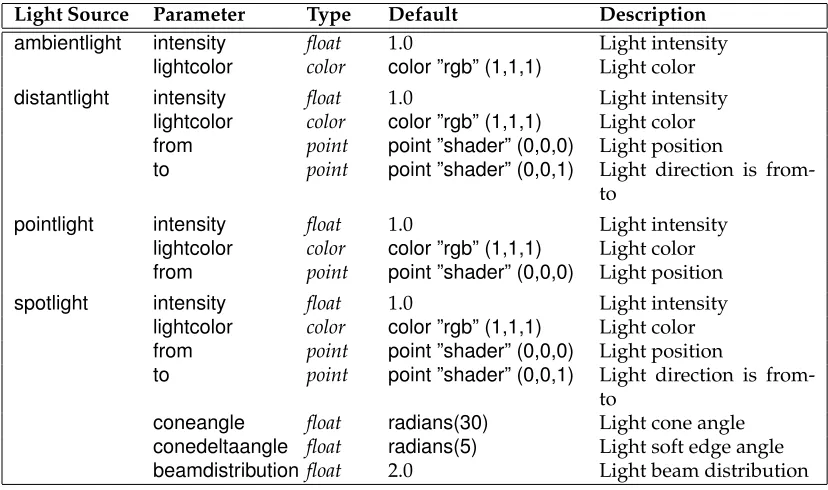
4.7 Standard Light Source Shader Parameters . . . 42
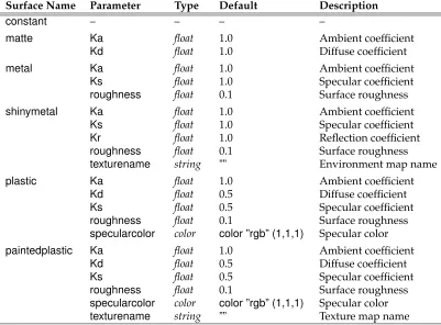
4.8 Standard Surface Shader Parameters . . . 45
4.9 Standard Displacement Shader Parameters . . . 46
4.10 Standard Volume Shader Parameters . . . 47
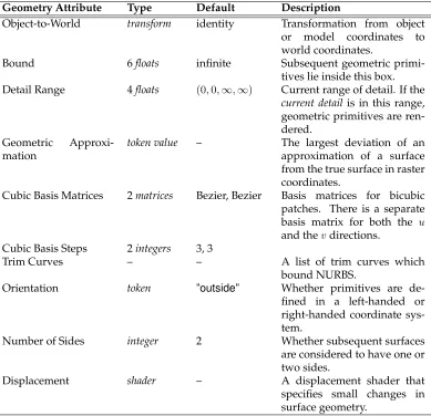
4.11 Geometry Attributes . . . 50
4.12 Typical implementation-specific attributes . . . 61
5.1 Standard Geometric Primitive Variables . . . 64
5.2 RiBlobbyopcodes for primitive fields. . . 86
5.3 RiBlobbyopcodes for combining fields. . . 87
6.1 Moving Commands . . . 98
10.1 Standard Shaders . . . 113
11.1 Color Coordinate Systems. . . 115
11.2 Point coordinate systems. . . 116
12.1 Predefined Surface Shader Variables . . . 121
12.2 Predefined Light Source Variables . . . 123
12.3 Predefined Volume Shader Variables . . . 123
12.4 Predefined Displacement Shader Variables . . . 124
12.5 Predefined Imager Shader Variables . . . 124
15.1 Texture and Environment Map Access Parameters . . . 144
15.2 Shadow Map Access Parameters . . . 147
15.3 Data names known to thetextureinfofunction. . . 147
15.4 Data names known to theattributefunction. . . 149
15.5 Data names known to theoptionfunction. . . 149
15.6 Data names known to therendererinfofunction. . . 150
PREFACE
This document is version 3.2 of the RenderMan Interface Specification, issued July, 2000. It supercedes version 3.1, originally published in September, 1989 and revised in July, 1995, and version 3.0, originally published in May, 1988.
Version 3.2 makes fundamental changes to version 3.1, including the addition of many new features, corrections of unclear or ambiguous material, and deletion of API calls that have been depricated over the years.
This document is the official technical specification for the RenderMan Interface. It is quite terse and requires substantial prior knowledge of computer graphics in general and pho-torealistic image synthesis in particular. For a more casual reference to the RenderMan Interface, the reader is directed toAdvanced RenderMan: Creating CGI for Motion Pictures (Anthony Apodaca and Larry Gritz, 1999). The first and second printings of Advanced RenderMancorrespond (except for minor errata) to version 3.2 of the RenderMan Interface Specification. Readers are also directed toThe RenderMan Companion: A Programmer’s Guide to Realistic Computer Graphics(Steve Upstill 1989), which corresponds (except for minor er-rata) to version 3.1 of the RenderMan Interface Specification.
Appendix I gives an overview of what has changed between version 3.1 and 3.2 of the RenderMan Interface Specification.
Part I
Section 1
INTRODUCTION
The RenderMan Interface is a standard interface between modeling programs and render-ing programs capable of producrender-ing photorealistic quality images. A renderrender-ing program implementing the RenderMan Interface differs from an implementation of earlier graphics standards in that:
• A photorealistic rendering program must simulate a real camera and its many at-tributes besides just position and direction of view. High quality implies that the simulation does not introduce artifacts from the computational process. Expressed in the terminology of computer graphics, this means that a photorealistic rendering program must be capable of:
– hidden surface removal so that only visible objects appear in the computed im-age,
– spatial filtering so that aliasing artifacts are not present, – dithering so that quantization artifacts are not noticeable,
– temporal filtering so that the opening and closing of the shutter causes moving objects to be blurred,
– and depth of field so that only objects at the current focal distance are sharply in focus.
• A photorealistic rendering program must also accept curved geometric primitives so that not only can geometry be accurately displayed, but also so that the basic shapes are rich enough to include the diversity of man-made and natural objects. This requires patches, quadrics, and representations of solids, as well as the ability to deal with complicated scenes containing on the order of 10,000 to 1,000,000 geometric primitives.
onto a surface. Texture maps are used in many different ways: direct image mapping to change the surface’s color, transparency mapping, bump mapping for changing its normal vector, displacement mapping for modifying position, environment or re-flection mapping for efficiently calculating global illumination, and shadow maps for simulating the presence of shadows.
The RenderMan Interface is designed so that the information needed to specify a photore-alistic image can be passed to different rendering programs compactly and efficiently. The interface itself is designed to drive different hardware devices, software implementations and rendering algorithms. Many types of rendering systems are accommodated by this in-terface, including z-buffer-based, scanline-based, ray tracing, terrain rendering, molecule or sphere rendering and the Reyes rendering architecture. In order to achieve this, the interface does not specify how a picture is rendered, but instead specifies what picture is desired. The interface is designed to be used by both batch-oriented and real-time inter-active rendering systems. Real-time rendering is accommodated by ensuring that all the information needed to draw a particular geometric primitive is available when the prim-itive is defined. Both batch and real-time rendering is accommodated by making limited use of inquiry functions and call-backs.
The RenderMan Interface is meant to be complete, but minimal, in its transfer of scene descriptions from modeling programs to rendering programs. The interface usually pro-vides only a single way to communicate a parameter; it is expected that the modeling front end will provide other convenient variations. An example is color coordinate systems – the RenderMan Interface supports multiple-component color models because a rendering program intrinsically computes with an n-component color model. However, the Render-Man Interface does not support all color coordinate systems because there are so many and because they must normally be immediately converted to the color representation used by the rendering program. Another example is geometric primitives – the primitives defined by the RenderMan Interface are considered to be rendering primitives, not modeling prim-itives. The primitives were chosen either because special graphics algorithms or hardware is available to draw those primitives, or because they allow for a compact representation of a large database. The task of converting higher-level modeling primitives to rendering primitives must be done by the modeling program.
The RenderMan Interface is not designed to be a complete three-dimensional interactive programming environment. Such an environment would include many capabilities not addressed in this interface. These include: 1) screen space or two-dimensional primitives such as annotation text, markers, and 2-D lines and curves, and 2) user-interface issues such as window systems, input devices, events, selecting, highlighting, and incremental redisplay.
The RenderMan Interface is a collection of procedures to transfer the description of a scene to the rendering program. These procedures are described in Part I. A rendering program takes this input and produces an image. This image can be immediately displayed on a given display device or saved in an image file. The output image may contain color as well as coverage and depth information for postprocessing. Image files are also used to input texture maps. This document does not specify a ”standard format” for image files.
created using this language. This language is also used to specify volumetric attenuation, displacements, and simple image processing functions. All required shading functionality is also expressed in this language. A shading language is an essential part of a high-quality rendering program. No single material lighting equation can ever hope to model the com-plexity of all possible material models. The RenderMan Shading Language is described in Part II of this document.
1.1
Features and Capabilities
The RenderMan Interface was designed in a top-down fashion by asking what information is needed to specify a scene in enough detail so that a photorealistic image can be created. Photorealistic image synthesis is quite challenging and many rendering programs cannot implement all of the features provided by the RenderMan Interface. This section describes which features are required and which are considered advanced, and therefore optional, capabilities. The set of required features is extensive in order that application writers and end-users may reasonably expect basic compatibility between, and a high level of perfor-mance from, all implementations of the RenderMan Interface. Advanced capabilities are optional only in situations where it is reasonable to expect that some rendering programs are algorithmically incapable of supporting that capability, or where the capability is so advanced that it is reasonable to expect that most rendering implementations will not be able to provide it.
1.1.1
Required features
All rendering programs which implement the RenderMan Interface must implement the interface as specified in this document. Implementations which are provided as a linkable C library must provide entry points for all of the subroutines and functions, accepting the parameters as described in this specification. All of the predefined types, variables and constants (including the entire set of constantRtTokenvariables for the predefined string arguments to the various RenderMan Interface subroutines) must be provided. The C header fileri.h(see Appendix C, Language Binding Details) describes these data items. Implementations which are provided as prelinked standalone applications must accept as input the complete RenderMan Interface Bytestream (RIB). Such implementations may also provide a complete RenderMan Interface library as above, which contains subroutine stubs whose only function is to generate RIB.
All rendering programs which implement the RenderMan Interface must:
• provide the complete hierarchical graphics state, including the attribute and trans-formation stacks and the active light list.
• perform orthographic and perspective viewing transformations. • perform depth-based hidden-surface elimination.
• perform gamma correction and dithering before quantization.
• produce picture files containing any combination of RGB, A, and Z. The resolutions of these files must be as specified by the user.
• provide all of the geometric primitives described in the specification, and provide all of the standard primitive variables applicable to each primitive.
• provide the ability to perform shading calculations using user-supplied RenderMan Shading Language programs. (See Part II, The RenderMan Shading Language.) • provide the ability to index texture maps, environment maps, and shadow depth
maps. (See the section on Basic texture maps.)
• provide the fifteen standard light source, surface, volume, displacement, and imager shaders required by the specification. Any additional shaders, and any deviations from the standard shaders presented in this specification, must be documented by providing the equivalent shader expressed in the RenderMan Shading Language.
Rendering programs that implement the RenderMan Interface receive all of their data through the interface. There must not be additional subroutines required to control or provide data to the rendering program. Data items that are substantially similar to items already described in this specification will be supplied through the normal mechanisms, and not through any of the implementation-specific extension mechanisms (RiAttribute,
RiGeometryor RiOption). Rendering programs may not provide nonstandard alterna-tives to the existing mechanisms, such as any alternate language for programmable shad-ing.
1.1.2
Advanced Capabilities
Rendering programs may also provide one or more of the following advanced capabilities, though it is recognized that algorithmic limitations of a particular implementation may restrict its ability to provide the entire feature set. If a capability is not provided by an implementation, a specific default is required (as described in the individual sections). A subset of the full functionality of a capability may be provided by a rendering program. For example, a rendering program might implement Motion Blur, but only of simple trans-formations, or only using a limited range of shutter times. Rendering programs should describe their implementation of the following optional capabilities using the terminology in the following list.
Solid Modeling The ability to define solid models as collections of surfaces and combine them using the set operations intersection, union and difference. (See the section on Solids and Spatial Set Operations, p. 92.)
Level of Detail The ability to specify several definitions of the same model and have one selected based on the estimated screen size of the model. (See the section onDetail, p. 51.)
Depth of Field The ability to simulate focusing at different depths. (See the section on Camera, p. 19.)
Special Camera Projections The ability to perform nonstandard camera projections such as spherical or Omnimax projections. (See the section onCamera, p. 19.)
Displacements The ability to handle displacements. (See the section onTransformations, p. 55.)
Spectral Colors The ability to calculate colors with an arbitrary number of spectral color samples. (See the section onAdditional Options, p. 34.)
Volume Shading The ability to attach and evaluate volumetric shading procedures. (See the section onVolume shading, p. 46.)
Ray Tracing The ability to evaluate global illumination models using ray tracing. (See the section onShading and Lighting Functions, p. 141.)
Global Illumination The ability to evaluate indirect illumination models using radiosity or other global illumination techniques. (See the section onIlluminance and Illuminate Statements, p. 127.)
Area Light Sources The ability to illuminate surfaces with area light sources. (See the sec-tion onLight Sources, p. 41.)
1.2
Structure of this Document
Section 2
LANGUAGE BINDING SUMMARY
In this document, the RenderMan Interface is described in the ANSI C language. Other language bindings may be proposed in the future.
2.1
C Binding
All types, procedures, tokens, predefined variables and utility procedures mentioned in this document are required to be present in all C implementations that conform to this specification. The C header file which declares all of these required names,ri.h, is listed in Appendix C, Language Binding Details.
The RenderMan Interface requires the following types:
typedef short RtBoolean; typedef int RtInt; typedef float RtFloat; typedef char *RtToken; typedefRtFloat RtColor[3]; typedefRtFloat RtPoint[3]; typedefRtFloat RtVector[3]; typedefRtFloat RtNormal[3]; typedefRtFloat RtHpoint[4]; typedefRtFloat RtMatrix[4][4]; typedefRtFloat RtBasis[4][4]; typedefRtFloat RtBound[6]; typedef char *RtString; typedef void *RtPointer; typedef void RtVoid;
typedefRtFloat (RtFilterFunc)(RtFloat,RtFloat,RtFloat,RtFloat); typedefRtFloat (RtErrorHandler)(RtInt,RtInt, char *);
typedefRtFloat (RtProcSubdivFunc)(RtPointer,RtFloat); typedefRtFloat (RtProcFreeFunc)(RtPointer);
typedefRtPointer RtLightHandle; typedefRtPointer RtContextHandle;
All procedures and values defined in the interface are prefixed withRi(for RenderMan Interface). All types are prefixed withRt(for RenderMan type). Boolean values are either RI FALSEorRI TRUE. Special floating point valuesRI INFINITYandRI EPSILONare de-fined. The expression−RI INFINITYhas the obvious meaning. The number of components in a color is initially three, but can be changed (See the section Additional options, p. 33). A bound is a bounding box and is specified by 6 floating point values in the orderxmin, xmax, ymin, ymax, zmin, zmax. A matrix is an array of 16 numbers describing a 4 by 4 transfor-mation matrix. All multidimensional arrays are specified in row-major order, and points are assumed to be represented as row vectors, not column vectors. For example, a 4 by 4 translation matrix to the location (2,3,4) is specified with
{ {1.0, 0.0, 0.0, 0.0}, {0.0, 1.0, 0.0, 0.0}, {0.0, 0.0, 1.0, 0.0}, {2.0, 3.0, 4.0, 1.0} }
Tokens are strings that have a special meaning to procedures implementing the interface. These meanings are described with each procedure. The capabilities of the RenderMan In-terface can be extended by defining new tokens and passing them to various procedures. The most important of these are the tokens identifying variables defined by procedures called shaders, written in the Shading Language. Variables passed through the Render-Man Interface are bound by name to shader variables. To make the standard predeclared tokens and user-defined tokens similar, RenderMan Interface tokens are represented by strings. Associated with each of the standard predefined tokens, however, is a predefined string constant that the RenderMan Interface procedures can use for efficient parsing. The names of these string constants are derived from the token names used in this document by prepending anRI to a capitalized version of the string. For example, the predefined constant token for”rgb”isRI RGB. The special predefined tokenRI NULLis used to specify anulltoken.
In the C binding presented in this document, parameters are passed by value or by refer-ence. C implementations of the RenderMan Interface are expected to make copies of any parameters whose values are to be retained across procedure invocations.
Many procedures in the RenderMan Interface have variable length parameter lists. These are indicated by the syntactical construct...parameterlist...in the procedure’s argument list. In the C binding described, aparameterlistis a sequence of pairs of arguments, the first being anRtTokenand the second being anRtPointer, an untyped pointer to an array of either
RtFloat,RtStringor other values. The list is terminated by the special tokenRI NULL.
In addition, each such procedure has an alternate vector interface, which passes theparameterlist as three arguments: anRtIntindicating the length of the parameter list; an array of that length that contains theRtTokens; and another array of the same length that contains the
RtPointers. This alternate procedure is denoted by appending an uppercase V to the pro-cedure name.
RiFoo(...parameterlist...) could be called in the following ways:
RtColorcolors;
RtPointpoints;
RtFloatone float;
RtTokentokens[3];
RtPointervalues[3];
RiFoo( RI NULL);
RiFoo((RtToken)”P”, (RtPointer)points, (RtToken)”Cs”, (RtPointer)colors, (RtToken)”Kd”, (RtPointer)&one float, RI NULL);
RiFoo(RI P, (RtPointer)points, RI CS, (RtPointer)colors, RI KD, (RtPointer)&one float, RI NULL); tokens[0] = RI P; values[0] = (RtPointer)points; tokens[1] = RI CS; values[1] = (RtPointer)colors; tokens[2] = RI KD; values[2] = (RtPointer)&one float;
RiFooV( 3, tokens, values);
It is not the intent of this document to propose that other language bindings use an identical mechanism for passing parameter lists. For example, a Fortran or Pascal binding might pass parameters using four arguments: an integer indicating the length of the parameter list, an array of that length that contains the tokens, an array of the same length containing integer indices into the final array containing the real values. A Common Lisp binding would be particularly simple because it has intrinsic support for variable length argument lists.
There may be more than onerendering context. This would allow a program to, for example, output to mutiple RIB files. RenderMan Interface procedure calls apply to the currently active context. At any one time, there is at most one globally active rendering context. The RenderMan Interface is not intended to be reentrant. In other words, the active context is truly global to a program process, and there cannot be have multiple simultaneous threads in one process, each with a different active context. Following is an example of writing to multiple contexts, in which a sphere is written to one RIB file and a cylinder is written to a different RIB file (the semantics of the context switching routines are presented in Section 4).
RtContextHandlectx1, ctx2;
RiBegin(”file1.rib”); ctx1 =RiGetContext( );
RiBegin(”file2.rib”); ctx2 =RiGetContext( ); ...
RiContext(ctx1);
RiSphere(1, -1, 1, 360, RI NULL);
RiContext(ctx2);
RiCylinder(1, -1, 1, 360, RI NULL);
RiContext(ctx1); ...
There is no RIB equivalent for context switching. Additionally, other language bindings may have no need for these routines, or may provide an obvious mechanism in the lan-guage for this facility (such as class instances and methods in C++).
2.2
Bytestream Protocol
This document also describes a byte stream representation of the RenderMan Interface, known as the RenderMan Interface Bytestream, or RIB. This byte stream serves as both a network transport protocol for modeling system clients to communicate requests to a remote rendering service, and an archive file format to save requests for later submission to a renderer.
The RIB protocol provides both an ASCII and binary encoding of each request, in order to satisfy needs for both an understandable (potentially) interactive interface to a rendering server and a compact encoded format which minimizes transmission time and file storage costs. Some requests have multiple versions, for efficiency or to denote special cases of the request.
The semantics of each RIB request are identical to the corresponding C entry point, except as specifically noted in the text. In Part I of this document, each RIB request is presented in its ASCII encoding, using the following format:
RIB BINDING
Requestparameter1 parameter2... parameterN
Explanation of the special semantics of the RIB protocol for this request.
At the top of the description,parameter1throughparameterNare the parameters that the re-quest requires. The notation ‘–’ in the parameter position indicates that the rere-quest expects no parameters. Normally the parameter names suggest their purpose, e.g.,x,y, orangle. In RIB, square brackets ([and]) delimit arrays. Integers will be automatically promoted if supplied for parameters which require floating point values. A parameter list is simply a sequence of string-array pairs. There is no explicit termination symbol as in the C binding. Example parameter lists are:
”P” [0 1 2 3 4 5 6 7 8 9 10 11] ”distance” [.5] ”roughness” [1.2]
2.3
Additional Information
Finally, the description of each RenderMan Interface request provides an example and cross-reference in the following format:
EXAMPLE
Request7 22.9 SEE ALSO
RiOtherRequest
Section 3
RELATIONSHIP TO THE RENDERMAN SHADING
LANGUAGE
The capabilities of the RenderMan Interface can be extended by using the Shading Lan-guage. The Shading Language is described in Part II of this document. This section de-scribes the interaction between the RenderMan Interface and the Shading Language. Special procedures, called shaders, are declared in this language. The argument list of a shader declares variables that can be passed through the RenderMan Interface to a shader. For example, in the shading language a shader calledweirdmight be declared as follows:
surface
weird ( float f = 1.0; point p = (0,0,0) ) {
Cs = Ci * mod ( length(P-p)*f - s + t, 1.0 ); }
The shaderweirdis referred to by name and so are its variables.
RtFloatfoo;
RtPointbar;
RiSurface(”weird”, ”f”, (RtPointer)&foo, ”p”, (RtPointer)&bar, RI NULL);
passes the value offooto the Shading Language variablefand the valuebarto the variable
p. Note that since all parameters are passed as arrays, the single float must be passed by reference.
In order to pass shading language variables, the RenderMan Interface must know the type of each variable defined in a shader. All predefined shaders predeclare the types of the variables that they use. Certain other variables, such as position, are also predeclared. Additional variables are declared with:
RtToken
Declare the name and type of a variable. The declaration indicates the size and se-mantics of values associated with the variable, or may be RI NULLif there are no associated values. This information is used by the renderer in processing the variable argument list semantics of the RenderMan Interface. The syntax ofdeclarationis:
[class] [type] [ ‘[’n‘]’ ]
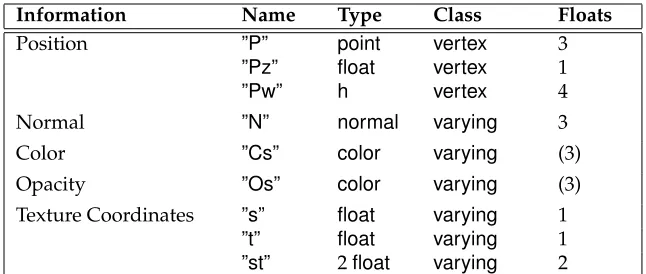
where class may beconstant,uniform,varying(as in the shading language), orvertex (position data, such as bicubic control points), and type may be one of:float,integer, string,color,point,vector,normal,matrix, andhpoint. Most of these types are described in Section 11, Types, which describes the data types available in the Shading Lan-guage. The Shading Language does not have an integertype, but integers may be passed through the interface as arguments to options or attributes. Additionally, the hpoint is used to describe 4D homogeneous coordinates (for example, used to de-scribe NURBS control points). Anyhpointvalues are converted to ordinarypointsby dividing by the homogeneous coordinate just before passing the value to the shader. The optional bracket notation indicates an array ofn typeitems, wherenis a positive integer. If no array is specified, one item is assumed. If aclass is not specified, the identifier is assumed to beuniform.
RiDeclare also installsname into the set of known tokens and returns a constant token which can be used to indicate that variable. This constant token will gener-ally have the same efficient parsing properties as the ‘RI’ versions of the predefined tokens.
RIB BINDING
Declarename declaration
EXAMPLE
RiDeclare( ”Np”, ”uniform point” );
RiDeclare( ”Cs”, ”varying color” );
Declare”st” ”varying float[2]”
In addition to using RiDeclare to globally declare the type of a variable, the type and storage class of a variable may be declared “in-line.” For example:
RiSurface( ”mysurf”, ”uniform point center”, ¢er, RI NULL );
RiPolygon( 4, RI P, &points, ”varying float temperature”, &temps, RI NULL );
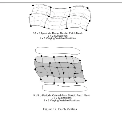
Patch”bilinear” ”P” [...] ”vertex point Pref” [...] ”varying float[2] st” [...]
through the interface. Any place where user data is used and would normally require a preceedingRiDeclare, it is also legal to use an in-line declaration.
The storage modifiersvertex,varying,uniform, andconstantare discussed in the section on Uniform and Varying Variables in Part II and in Section 5, Geometric Primitives. All proce-dure parameter tokens and shader variable name tokens named in this document are stan-dard and are predefined by all implementations of the RenderMan Interface. In addition, a particular implementation may predeclare other variables for use with implementation-specific options, geometry, etc.
Whenever apoint,vector,normal,matrix, orhpointvariable is passed through the Render-Man Interface to shaders, the values are assumed to be relative to the current coordinate system. This is sometimes referred to asobjectcoordinates. Different coordinate systems are discussed in the Camera section.
Section 4
GRAPHICS STATE
The RenderMan Interface is similar to other graphics packages in that it maintains a graph-ics state. The graphics state contains all the information needed to render a geometric primitive. RenderMan Interface commands either change the graphics state or render a geometric primitive. The graphics state is divided into two parts: a global state that re-mains constant while rendering a single image or frame of a sequence, and a current state that changes from geometric primitive to geometric primitive. Parameters in the global state are referred to asoptions, whereas parameters in the current state are referred to as attributes. Options include the camera and display parameters, and other parameters that affect the quality or type of rendering in general (e.g., global level of detail, number of color samples, etc.). Attributes include the parameters controlling appearance or shading (e.g., color, opacity, surface shading model, light sources, etc.), how geometry is interpreted (e.g., orientation, subdivision level, bounding box, etc.), and the current modeling matrix. To aid in specifying hierarchical models, the attributes in the graphics state may be pushed and popped on a graphics state stack.
The graphics state also maintains the interfacemode. The different modes of the interface are entered and exited by matching Begin-End command sequences.
RiBegin(RtTokenname)
RiEnd( void )
RiBegin creates and initializes a new rendering context, setting all graphics state variables to their default values, and makes the new context the active one to which subsequentRiroutines will apply. Any previously active rendering context still ex-ists, but is no longer the active one. Thenamemay be the name of a renderer, to select among various implementations that may be available, or the name of the file to write (in the case of a RIB generator). RI NULLindicates that the default implementation and/or output file should be used.
RiEnd terminates the active rendering context, including performing any cleanup operations that need to be done. AfterRiEndis called, there is no active rendering context until anotherRiBeginorRiContextis called.
RtContextHandle RiGetContext( void )
RiContext(RtContextHandlehandle)
RiGetContextreturns a handle for the current active rendering context. If there is no active rendering context,RI NULLwill be returned.RiContextsets the current active rendering context to be the one pointed to byhandle. Any previously active context is not destroyed.
There is no RIB equivalent for these routines. Additionally, other language bindings may have no need for these routines, or may provide an obvious mechanism in the language for this facility (such as class instances and methods in C++).
RiFrameBegin(RtIntframe)
RiFrameEnd( void )
The bracketed set of commands RiFrameBegin-RiFrameEnd mark the beginning and end of a single frame of an animated sequence. frame is the number of this frame. The values of all of the rendering options are saved whenRiFrameBeginis called, and these values are restored whenRiFrameEndis called.
All lights and retained objects defined inside theRiFrameBegin-RiFrameEndframe block are removed and their storage reclaimed when RiFrameEnd is called (thus invalidating their handles).
All of the information that changes from frame to frame should be inside a frame block. In this way, all of the information that is necessary to produce a single frame of an animated sequence may be extracted from a command stream by retaining only those commands within the appropriate frame block and any commands outside all of the frame blocks. This command need not be used if the application is producing a single image.
RIB BINDING
FrameBeginint
FrameEnd -EXAMPLE
RiFrameBegin(14); SEE ALSO
RiWorldBegin
RiWorldBegin()
When RiWorldBegin is invoked, all rendering options are frozen and cannot be changed until the picture is finished. Theworld-to-camera transformationis set to the current transformationand thecurrent transformationis reinitialized to the identity. In-side anRiWorldBegin-RiWorldEndblock, thecurrent transformationis interpreted to be theobject-to-world transformation. After anRiWorldBegin, the interface can accept geometric primitives that define the scene. (The only other mode in which geomet-ric primitives may be defined is inside aRiObjectBegin-RiObjectEndblock.) Some rendering programs may immediately begin rendering geometric primitives as they are defined, whereas other rendering programs may wait until the entire scene has been defined.
RiWorldEnddoes not normally return until the rendering program has completed drawing the image. If the image is to be saved in a file, this is done automatically by
RiWorldEnd.
All lights and retained objects defined inside theRiWorldBegin-RiWorldEndworld block are removed and their storage reclaimed whenRiWorldEndis called (thus in-validating their handles).
RIB BINDING
WorldBegin
-WorldEnd -EXAMPLE
RiWorldEnd(); SEE ALSO
RiFrameBegin
The following is an example of the use of these procedures, showing how an application constructing an animation might be structured. In the example, an object is defined once and instanced in subsequent frames at different positions.
RtObjectHandleBigUglyObject;
RiBegin();
BigUglyObject =RiObjectBegin(); ...
RiObjectEnd(); /* Display commands */
RiDisplay(...):
RiFormat(...);
RiFrameAspectRatio(1.0);
RiScreenWindow(...);
RiFrameBegin(0);
/* Camera commands */
RiProjection(RI PERSPECTIVE,...);
RiWorldBegin(); ...
RiColor(...);
RiTranslate(...);
RiObjectInstance( BigUglyObject ); ...
RiWorldEnd();
RiFrameEnd();
RiFrameBegin(1);
/* Camera commands */
RiProjection(RI PERSPECTIVE,...);
RiRotate(...);
RiWorldBegin(); ...
RiColor(...);
RiTranslate(...);
RiObjectInstance( BigUglyObject ); ...
RiWorldEnd();
RiFrameEnd(); ...
RiEnd();
The following begin-end pairs also place the interface into special modes.
RiSolidBegin()
RiSolidEnd()
RiMotionBegin()
RiMotionEnd()
RiObjectBegin()
RiObjectEnd()
The properties of these modes are described in the appropriate sections (see the sections onSolids and Spatial Set Operations, p. 92;Motion, p. 96; andRetained Geometry, p. 94). Two other begin-end pairs:
RiAttributeBegin()
RiAttributeEnd()
RiTransformBegin()
RiTransformEnd()
save and restore the attributes in the graphics state, and save and restore the current trans-formation, respectively.
may be nested to any depth, subject to their individual restrictions, but it is never legal for the blocks to overlap.
4.1
Options
The graphics state has variousoptionsthat must be set before rendering a frame. The com-plete set of options includes: a description of the camera, which controls all aspects of the imaging process (including the camera position and the type of projection); a description of the display, which controls the output of pixels (including the types of images desired, how they are quantized and which device they are displayed on); as well as renderer run-time controls (such as the hidden surface algorithm to use).
4.1.1
Camera
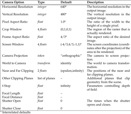
The graphics state contains a set of parameters that define the properties of the camera. The complete set of camera options is described in Table 4.1, Camera Options.
The viewing transformation specifies the coordinate transformations involved with imag-ing the scene onto an image plane and samplimag-ing that image at integer locations to form a raster of pixel values. A few of these procedures set display parameters such asresolution andpixel aspect ratio. If the rendering program is designed to output to a particular display device these parameters are initialized in advance. Explicitly setting these makes the spec-ification of an image more device dependent and should only be used if necessary. The defaults given in theCamera Optionstable characterize a hypothetical framebuffer and are the defaults for picture files.
The camera model supports near and far clipping planes that are perpendicular to the viewing direction, as well as any number of arbitrary user-specified clipping planes. Depth of field is specified by setting an f-stop, focal length, and focal distance just as in a real camera. Objects located at the focal distance will be sharp and in focus while other objects will be out of focus. The shutter is specified by giving opening and closing times. Moving objects will blur while the camera shutter is open.
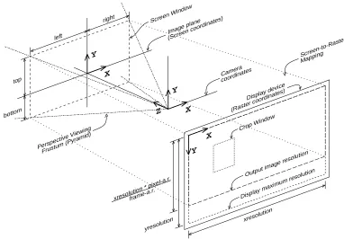
The imaging transformation proceeds in several stages. Geometric primitives are specified in the object coordinate system. This canonical coordinate system is the one in which the object is most naturally described. The object coordinates are converted to the world co-ordinate system by a sequence ofmodeling transformations. The world coordinate system is converted to the camera coordinate system by the camera transformation. Once in camera coordinates, points are projected onto the image plane or screen coordinate system by the projection and its following screen transformation. Points on the screen are finally mapped to a device dependent, integer coordinate system in which the image is sampled. This is referred to as the raster coordinate system and this transformation is referred to as the raster transformation. These various coordinate systems are summarized in Table 4.2 Point Coordinate Systems.
Camera Option Type Default Description
Horizontal Resolution integer 640* The horizontal resolution in the output image.
Vertical Resolution integer 480* The vertical resolution in the output image.
Pixel Aspect Ratio float 1.0* The ratio of the width to the height of a single pixel.
Crop Window 4floats (0,1,0,1) The region of the raster that is actually rendered.
Frame Aspect Ratio float 4/3* The aspect ratio of the desired image.
Screen Window 4floats (-4/3,4/3,-1,1)* The screen coordinates (coordi-nates after the projection) of the area to be rendered.
Camera Projection token “orthographic” The camera to screen projec-tion.
World to Camera transform identity The world to camera transfor-mation.
Near and Far Clipping 2floats (epsilon,infinity) The positions of the near and far clipping planes.
Other Clipping Planes list of planes – Additional planes that clip geometry from the scene.
f-Stop float infinity Parameters controlling depth
of field.
Focal Length float –
Focal Distance float –
Shutter Open float 0 The times when the shutter
opens and closes.
Shutter Close float 0
[image:31.612.107.524.220.582.2]* Interrelated defaults
Coordiante System Description
”object” The coordinate system in which the current geometric primitive is defined. The modeling transformation converts from object coor-dinates to world coorcoor-dinates.
”world” The standard reference coordinate system. The camera transfor-mation converts from world coordinates to camera coordinates. ”camera” A coordinate system with the vantage point at the origin and the
direction of view along the positive z-axis. The projection and screen transformation convert from camera coordinates to screen coordinates.
”screen” The 2-D normalized coordinate system corresponding to the im-age plane. The raster transformation converts to raster coordi-nates.
”raster” The raster or pixel coordinate system. An area of 1 in this nate system corresponds to the area of a single pixel. This coordi-nate system is either inherited from the display or set by selecting the resolution of the image desired.
”NDC” Normalized device coordinates — like”raster”space, but normal-ized so that xandy both run from 0 to 1 across the whole (un-cropped) image, with (0,0) being at the upper left of the image, and (1,1) being at the lower right (regardless of the actual aspect ratio).
Table 4.2: Point Coordinate Systems
imaging process was described above. WhenRiBeginis executed it establishes a complete set of defaults. If the rendering program is designed to produce pictures for a particular piece of hardware, display parameters associated with that piece of hardware are used. If the rendering program is designed to produce picture files, the parameters are set to gen-erate a video-size image. If these are not sufficient, the resolution and pixel aspect ratio can be set to generate a picture for any display device. RiBeginalso establishes default screen and camera coordinate systems as well. The default projection is orthographic and the screen coordinates assigned to the display are roughly between±1.0. The initial cam-era coordinate system is mapped onto the display such that the +x axis points right, the+y axis points up, and the+zaxis points inward, perpendicular to the display surface. Note that this is left-handed.
Before any transformation commands are made, thecurrent transformation matrixcontains the identity matrix as the screen transformation. Usually the first transformation command is anRiProjection, which appends the projection matrix onto the screen transformation, saves it, and reinitializes thecurrent transformation matrixas the identity camera transforma-tion. This marks the current coordinate system as the camera coordinate system. After the camera coordinate system is established, future transformations move the world coordi-nate system relative to the camera coordicoordi-nate system. When anRiWorldBeginis executed, thecurrent transformation matrixis saved as the camera transformation, and thus the world coordinate system is established. Subsequent transformations inside of anRiWorldBegin
xresolution xresolution * pixel-a.r.frame-a.r.
yresolution
X
Y
Crop Window
Output image resolution
Display maximum resolution Display device
(Raster coordinates)
X Y
Image plane (Screen coordinates) left
right
top
bottom
Screen Window
X Y
Z
Camera coordinates
Perspective Viewing Frustum (Pyramid)
[image:33.612.111.493.139.405.2]Screen-to-Raster Mapping
Figure 4.1: Camera-to-Raster Projection Geometry
The following example shows how to position a camera:
RiBegin();
RiFormat( xres, yres, 1.0 ); /* Raster coordinate system */
RiFrameAspectRatio( 4.0/3.0 ); /* Screen coordinate system */
RiFrameBegin(0);
RiProjection(”perspective,”...); /* Camera coordinate system */
RiRotate(... );
RiWorldBegin(); /* World coordinate system */
...
RiTransform(...); /* Object coordinate system */
RiWorldEnd();
RiFrameEnd();
RiEnd();
RiFormat(RtIntxresolution,RtIntyresolution,RtFloatpixelaspectratio)
Set the horizontal (xresolution) and vertical (yresolution) resolution (in pixels) of the image to be rendered. The upper left hand corner of the image has coordinates (0,0) and the lower right hand corner of the image has coordinates (xresolution, yreso-lution). If the resolution is greater than the maximum resolution of the device, the desired image is clipped to the device boundaries (rather than being shrunk to fit inside the device). This command also sets the pixel aspect ratio. The pixel aspect ratio is the ratio of the physical width to the height of a single pixel. The pixel aspect ratio should normally be set to 1 unless a picture is being computed specifically for a display device with non-square pixels.
Implicit in this command is the creation of a display viewport with a
viewportaspectratio= xresolution·pixelaspectratio
yresolution
The viewport aspect ratio is the ratio of the physical width to the height of the entire image.
An image of the desired aspect ratio can be specified in a device independent way us-ing the procedureRiFrameAspectRatiodescribed below. TheRiFormatcommand should only be used when an image of a specified resolution is needed or an image file is being created.
If this command is not given, the resolution defaults to that of the display device being used (see the Displays section, p. 27). Also, if xresolution, yresolution or pix-elaspectratio is specified as a nonpositive value, the resolution defaults to that of the display device for that particular parameter.
RIB BINDING
Formatxresolution yresolution pixelaspectratio
EXAMPLE
Format512 512 1 SEE ALSO
RiDisplay,RiFrameAspectRatio
RiFrameAspectRatio(RtFloatframeaspectratio )
frameaspectratio is the ratio of the width to the height of the desired image. The picture produced is adjusted in size so that it fits into the display area specified with
RiDisplay or RiFormatwith the specified frame aspect ratio and is such that the upper left corner is aligned with the upper left corner of the display.
If this procedure is not called, the frame aspect ratio defaults to that determined from the resolution and pixel aspect ratio.
RIB BINDING
EXAMPLE
RiFrameAspectRatio(4.0/3.0); SEE ALSO
RiDisplay,RiFormat
RiScreenWindow(RtFloatleft,RtFloatright,RtFloatbottom,RtFloattop )
This procedure defines a rectangle in the image plane that gets mapped to theraster coordinate system and that corresponds to the display area selected. The rectangle specified is in thescreen coordinate system. The valuesleft,right,bottom, andtopare mapped to the respective edges of the display.
The default values for the screen window coordinates are: (–frameaspectratio,frameaspectratio, –1, 1).
ifframeaspectratiois greater than or equal to one, or (–1, 1, –1/frameaspectratio, 1/frameaspectratio).
ifframeaspectratiois less than or equal to one. For perspective projections, this de-fault gives a centered image with the smaller of the horizontal and vertical fields of view equal to the field of view specified withRiProjection. Note that if the camera transformation preserves relativexandydistances, and if the ratio
abs(right−left)
abs(top−bottom)
is not the same as the frame aspect ratio of the display area, the displayed image will be distorted.
RIB BINDING
ScreenWindowleft right bottom top
ScreenWindow[left right bottom top] EXAMPLE
ScreenWindow-1 1 -1 1 SEE ALSO
RiCropWindow,RiFormat,RiFrameAspectRatio,RiProjection
RiCropWindow(RtFloatxmin,RtFloatxmax,RtFloatymin,RtFloatymax )
rxmin = clamp (ceil ( xresolution*xmin ), 0, xresolution-1); rxmax = clamp (ceil ( xresolution*xmax -1 ), 0, xresolution-1); rymin = clamp (ceil ( yresolution*ymin ), 0, yresolution-1); rymax = clamp (ceil ( yresolution*ymax -1 ), 0, yresolution-1);
These regions are defined so that if a large image is generated with tiles of abutting but non-overlapping crop windows, the subimages produced will tile the display with abutting and non-overlapping regions.
RIB BINDING
Cropwindowxmin xmax ymin ymax
Cropwindow[xmin xmax ymin ymax] EXAMPLE
RiCropWindow(0.0, 0.3, 0.0, 0.5); SEE ALSO
RiFrameAspectRatio,RiFormat
RiProjection(RtTokenname,...parameterlist...)
The projection determines how camera coordinates are converted to screen coordi-nates, using the type of projection and the near/far clipping planes to generate a projection matrix. It appends this projection matrix to thecurrent transformation ma-trix and stores this as the screen transformation, then marks the current coordinate system as the camera coordinate system and reinitializes thecurrent transformation matrixto the identity camera transformation. The required types of projection are ”perspective”,”orthographic”, andRI NULL.
”perspective”builds a projection matrix that does a perspective projection along the z-axis, using theRiClippingvalues, so that points on the near clipping plane project toz= 0and points on the far clipping plane project toz= 1.”perspective”takes one optional parameter,”fov”, a singleRtFloatthat indicates he full angle perspective field of view (in degrees) between screen space coordinates (-1,0) and (1,0) (equivalently between (0,-1) and (0,1)). The default is 90 degrees.
Note that there is a redundancy in the focal length implied by this procedure and the one set byRiDepthOfField. The focal length implied by this command is:
focallength= horizontalscreenwidth
verticalscreenwidth /tan
fov
2
”orthographic”builds a simple orthographic projection that scaleszusing the RiClip-pingvalues as above.”orthographic”takes no parameters.
RI NULLuses an identity projection matrix, and simply marks camera space in situa-tions where the user has generated his own projection matrices himself using RiPer-spectiveorRiTransform.
not support the special projection specified, it is ignored and an orthographic projec-tion is used. IfRiProjectionis not called, the screen transformation defaults to the identity matrix, so screen space and camera space are identical.
RIB BINDING
Projection”perspective”...parameterlist...
Projection”orthographic”
Projectionname ...parameterlist...
EXAMPLE
RiProjection(RI ORTHOGRAPHIC, RI NULL);
RtFloatfov = 45.0;
RiProjection(RI PERSPECTIVE, ”fov”, &fov, RI NULL); SEE ALSO
RiPerspective,RiClipping
RiClipping(RtFloatnear,RtFloatfar )
Sets the position of the near and far clipping planes along the direction of view.
near and far must both be positive numbers. near must be greater than or equal toRI EPSILONand less thanfar.far must be greater thannear and may be equal to RI INFINITY. These values are used byRiProjectionto generate a screen projection such that depth values are scaled to equal zero atz=near and one atz=far. Notice that the rendering system will actually clip geometry which lies outside of z=(0,1) in the screen coordinate system, so non-identity screen transforms may affect which objects are actually clipped.
For reasons of efficiency, it is generally a good idea to bound the scene tightly with the near and far clipping planes.
RIB BINDING
Clippingnear far
EXAMPLE
Clipping0.1 10000 SEE ALSO
RiBound,RiProjection,RiClippingPlane
Multiple calls toRiClippingPlanewill establish multiple clipping planes. RIB BINDING
ClippingPlanex y z nx ny nz
EXAMPLE
ClippingPlane3 0 0 0 0 -1 SEE ALSO
RiClipping
RiDepthOfField(RtFloatfstop,RtFloatfocallength,RtFloatfocaldistance )
focaldistancesets the distance along the direction of view at which objects will be in focus. focallengthsets the focal length of the camera. These two parameters should have the units of distance along the view direction in camera coordinates. fstop, or aperture number, determines the lens diameter:
lensdiameter = focallength
fstop
If fstop is RI INFINITY, a pin-hole camera is used and depth of field is effectively turned off. If theDepth of Fieldcapability is not supported by a particular implemen-tation, a pin-hole camera model is always used.
If depth of field is turned on, points at a particular depth will not image to a single point on the view plane but rather a circle. This circle is called thecircle of confusion. The diameter of this circle is equal to
C=focallength
fstop ·
focaldistance·focallength focaldistance−focallength ·
1
depth −
1
focaldistance
Note that there is a redundancy in the focal length as specified in this procedure and the one implied byRiProjection.
RIB BINDING
DepthOfFieldfstop focallength focaldistance
DepthOfField
-The second form specifies a pin-hole camera with infinitefstop, for which the focal-lengthandfocaldistanceparameters are meaningless.
EXAMPLE
DepthOfField22 45 1200 SEE ALSO
RiProjection
This procedure sets the times at which the shutter opens and closes. minshould be less thanmax. Ifmin==max, no motion blur is done.
RIB BINDING
Shuttermin max
EXAMPLE
RiShutter(0.1, 0.9); SEE ALSO
RiMotionBegin
4.1.2
Displays
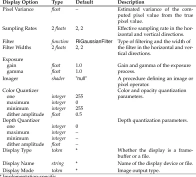
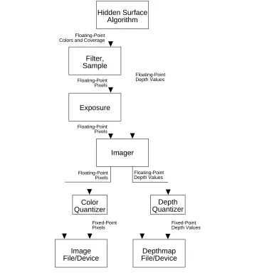
The graphics state contains a set of parameters that control the properties of the display process. The complete set of display options is given in Table 4.3, Display Options. Rendering programs must be able to produce color, coverage (alpha), and depth images, and may optionally be able to produce “images” of arbitrary geometric or shader-computed data. Display parameters control how the values in these images are converted into a dis-playable form. Many times it is possible to use none of the procedures described in this section. If this is done, the rendering process and the images it produces are described in a completely device-independent way. If a rendering program is designed for a specific dis-play, it has appropriate defaults for all display parameters. The defaults given in Table 4.3, Display Options characterize a file to be displayed on a hypothetical video framebuffer. The output process is different for color, alpha, and depth information. (See Figure 4.2, Imaging Pipeline). The hidden-surface algorithm will produce a representation of the light incident on the image plane. This color image is either continuous or sampled at a rate that may be higher than the resolution of the final image. The minimum sampling rate can be controlled directly, or can be indicated by the estimated variance of the pixel values. These color values are filtered with a user-selectable filter and filterwidth, and sampled at the pixel centers. The resulting color values are then multiplied by the gain and passed through an inverse gamma function to simulate the exposure process. The resulting colors are then passed to a quantizer which scales the values and optionally dithers them before converting them to a fixed-point integer. It is also possible to interpose a programmable imager (written in the Shading Language) between the exposure process and quantizer. This imager can be used to perform special effects processing, to compensate for nonlin-earities in the display media, and to convert to device dependent color spaces (such as CMYK or pseudocolor).
Display Option Type Default Description
Pixel Variance float – Estimated variance of the com-puted pixel value from the true pixel value.
Sampling Rates 2floats 2, 2 Effective sampling rate in the hor-izontal and vertical directions. Filter function RiGaussianFilter Type of filtering and the width of Filter Widths 2floats 2, 2 the filter in the horizontal and
ver-tical directions. Exposure
gain float 1.0 Gain and gamma of the exposure
gamma float 1.0 process.
Imager shader ”null” A procedure defining an image or pixel operator.
Color Quantizer Color and opacity quantization
one integer 255 parameters.
maximum integer 0
minimum integer 255 dither amplitude float 0.5
Depth Quantizer Depth quantization parameters.
one integer 0
maximum integer –
minimum integer –
dither amplitude float –
Display Type token * Whether the display is a frame-buffer or a file.
Display Name string * Name of the display device or file. Display Mode token * Image output type.
[image:40.612.109.501.223.577.2]* Implementation-specific
Output depth values are the camera-spacez values. Depth values bypass all the above steps except for the imager and quantization. The depth quantizer has an independent set of parameters from those of the color quantizer.
RiPixelVariance(RtFloatvariation )
The color of a pixel computed by the rendering program is an estimate of the true pixel value: the convolution of the continuous image with the filter specified by
RiPixelFilter. This routine sets the upper bound on the acceptable estimated vari-ance of the pixel values from the true pixel values.
RIB BINDING
PixelVariancevariation
EXAMPLE
RiPixelVariance(.01); SEE ALSO
RiPixelFilter,RiPixelSamples
RiPixelSamples(RtFloatxsamples,RtFloatysamples )
Set the effective hider sampling rate in the horizontal and vertical directions. The effective number of samples per pixel isxsamples*ysamples. If an analytic hidden surface calculation is being done, the effective sampling rate is RI INFINITY. Sam-pling rates less than 1 are clamped to 1.
RIB BINDING
PixelSamplesxsamples ysamples
EXAMPLE
PixelSamples2 2 SEE ALSO
RiPixelFilter,RiPixelVariance
RiPixelFilter(RtFilterFuncfilterfunc,RtFloatxwidth,RtFloatywidth )
Antialiasing is performed by filtering the geometry (or supersampling) and then sam-pling at pixel locations. The filterfunc controls the type of filter, while xwidth and
ywidthspecify the width of the filter in pixels. A value of 1 indicates that the support of the filter is one pixel. RenderMan supports nonrecursive, linear shift-invariant fil-ters. The type of the filter is set by passing a reference to a function that returns a filter kernel value; i.e.,
Fixed-Point Pixels Floating-Point
Pixels
Fixed-Point Depth Values Floating-Point
Depth Values Floating-Point Depth Values
Floating-Point Pixels Floating-Point Pixels Floating-Point Colors and Coverage
Imager Exposure
Image File/Device
Color Quantizer
Depth Quantizer
Depthmap File/Device Filter,
Sample
[image:42.612.125.517.139.526.2]Hidden Surface Algorithm
Figure 4.2: Imaging pipeline
(where (x,y) is the point at which the filter should be evaluated). The rendering program only requests values in the ranges –xwidth/2 to xwidth/2 and –ywidth/2 toywidth/2. The values returned need not be normalized.
The following standard filter functions are available:
RtFloat RiBoxFilter(RtFloat,RtFloat,RtFloat,RtFloat);
RtFloat RiTriangleFilter(RtFloat,RtFloat,RtFloat,RtFloat);
RtFloat RiCatmullRomFilter(RtFloat,RtFloat,RtFloat,RtFloat);
RtFloat RiGaussianFilter(RtFloat,RtFloat,RtFloat,RtFloat);
A particular renderer implementation may also choose to provide additional built-in filters. The standard filters are described in Appendix E.
A high-resolution picture is often computed in sections or panels. Each panel is a subrectangle of the final image. It is important that separately computed panels join together without a visible discontinuity or seam. If the filter width is greater than 1 pixel, the rendering program must compute samples outside the visible window to properly filter before sampling.
RIB BINDING
PixelFiltertype xwidth ywidth
Thetypeis one of:”box”,”triangle”,”catmull-rom”(cubic),”sinc”, and”gaussian”. EXAMPLE
RiPixelFilter(RiGaussianFilter, 2.0, 1.0);
PixelFilter”gaussian” 2 1 SEE ALSO
RiPixelSamples,RiPixelVariance
RiExposure(RtFloatgain,RtFloatgamma )
This function controls the sensitivity and nonlinearity of the exposure process. Each component of color is passed through the following function:
color= (color·gain)1/gamma
RIB BINDING
Exposuregain gamma
EXAMPLE
Exposure1.5 2.3 SEE ALSO
RiImager
RiImager(RtTokenname,...parameterlist...)
Select an imager function programmed in the Shading Language. nameis the name of animager shader. IfnameisRI NULL, noimager shaderis used.
RIB BINDING
Imagername ...parameterlist...
EXAMPLE
RiExposure
RiQuantize(RtTokentype,RtIntone,RtIntmin,RtIntmax,RtFloatditheramplitude ) Set the quantization parameters for colorsordepth. Iftypeis”rgba”, then color and opacity quantization are set. Iftypeis ”z”, then depth quantization is set. The value
onedefines the mapping from floating-point values to fixed point values. Ifoneis 0, then quantization is not done and values are output as floating point numbers. Dithering is performed by adding a random number to the floating-point values be-fore they are rounded to the nearest integer. The added value is scaled to lie between plus and minus the dither amplitude. Ifditheramplitudeis 0, dithering is turned off. Quantized values are computed using the following formula:
value=round(one*value+ditheramplitude*random() ); value=clamp(value,min,max );
whererandomreturns a random number between±1.0, andclampclips its first argu-ment so that it lies betweenminandmax.
By default color pixel values are dithered with an amplitude of 0.5 and quantization is performed for an 8-bit display with aoneof 255. Quantization and dithering and not performed for depth values (by default).
RIB BINDING
Quantizetype one min max ditheramplitude
EXAMPLE
RiQuantize(RI RGBA, 2048, -1024, 3071, 1.0); SEE ALSO
RiDisplay,RiImager
RiDisplay(RtTokenname,RtTokentype,RtTokenmode,...parameterlist...)