Department of Computer Science, University
of Liverpool, UK
Contact: Richard Stocker (R.S.Stocker@liverpool.ac.uk)
Towards the Formal Verification of
Human-Agent-Robot Teamwork
A PhD Thesis
ByRichard Stocker
Supervisors:
Prof. Michael Fisher Dr. Louise Dennis Dr. Clare Dixon
Reviewers: Dr. Wamberto Vasconcelos
Dr. Davide Grossi
June 6, 2013
Declaration
I hereby declare that this thesis is my own work and effort and that it has not been submitted anywhere else for any other award. Where other sources of information have been used, they have been acknowledged.
Acknowledgements
I would like to express my deepest appreciation to Prof. Michael Fisher, Dr. Clare Dixon, and Dr. Louise Dennis for their supervision of this thesis. Michael’s ability to explain the more difficult concepts in easy to read diagrams and his foresight of the advantages and disadvantages of the possible paths we could take made the project a lot less difficult to achieve. Louise’s technical knowhow of how to implement the tool we needed was of invaluable help. I also thank Louise for her uncanny ability in discussions to act as an interpreter between myself and Michael when I could not understand a question he asked or he could not understand a poorly explained answer I had given. Clare’s assistance for the theoretical aspects of the project was of immense help, providing guidance on how to structure the semantic rules. Clares advice on a multitude of areas, from technical and theoretical aspects to simple formatting of documents greatly improved every aspect of the thesis. Without the guidance and help of Michael, Clare and Louise this thesis would not have been possible.
I would like to thank Prof. Maarten Sierhuis for his assistance with the project. His understandings and explanations of the Brahms framework made it possible for us to create a formal operational semantics for Brahms. Also his guidance on applications of Brahms helped us to create the case studies for the thesis, most notably the digital nurse scenario.
Contributions to Learning in
Computer Science
This thesis:
• presents the first formal semantics for Brahms; Part II, Chapter 6, published in [79]
• presents the first formal verification tool specifically for human-agent teamwork; Part II, Chapter 7, published in [78]
• presents the first formal verification tool for the Brahms simulation framework; Part II, Chapter 7, published in [78]
Thesis Statement/Abstract
Thesis Structure
This thesis is structured into 4 Parts and 13 Chapters as follows:
Part I
Introduces the thesis and provides information on the tools and techniques used.
Chapter 1
introduces the thesis providing justification for undertaking the project.
Chapter 2
explains to the reader our concept of what an agent is, how it is used and the representation of agents in teams with both humans and other agents.
Chapter 3
introduces the agent simulation tool we use in this thesis (Brahms), ex-plaining its core functions and describes how it compares to other agent programming languages.
Chapter 4
explains our meaning of formal verification, introducing different types of formal verification, logics and agent verification.
Chapter 5
describes our analysis of how to conduct this project, from selecting the tools we used to the methods we employed.
Part II
Explains the development of the tool we created to formally verify human-agent team-work. Introducing our formal operational semantics for Brahms, the implementation of our model checking tool and another tool to formally verify Brahms using our oper-ational semantics.
Chapter 6
describes the formal operational semantics produced for this thesis.
describes the process of translating Brahms code intoPROMELA for Spin verification.
Chapter 8
describes NASAs Brahms verification tool developed using the formal oper-ational semantics produced for this thesis.
Part III
Details the case studies produced to test the correctness, effectiveness and performance of our tool.
Chapter 9
describes the home helper scenario, where a robotic helper assists a person with dementia.
Chapter 10
describes the digital nurse scenario, where doctors and nurses have digital assistants to help them treat patients.
Chapter 11
brings together all the conclusions formed from the analysis of the case studies.
Part IV
Contains our evaluation and conclusions of the tool produced. Here we also describe other methods used to evaluate the performance of the tool and their results.
Chapter 12
evaluates the performance of the verification tool on simple scalable tasks.
Chapter 13
Contents
Declaration i
Acknowledgements ii
Contributions to Computer Science iii
Abstract iv
Thesis Structure v
I Introduction and Background 1
1 Introduction 2
2 Software Agents 4
2.1 Agents . . . 4
2.2 Rational Agents . . . 5
2.2.1 Applications . . . 5
2.2.2 Humans as Agents . . . 6
2.3 Multi-Agent Systems . . . 6
2.3.1 Humans and Agents Working as a Team . . . 6
2.3.2 What is Teamwork? . . . 8
2.4 Beliefs-Desires-Intentions . . . 9
2.5 Chapter Summary . . . 11
3 Brahms 13 3.1 Basic Anatomy of Brahms . . . 13
3.1.1 Geography . . . 13
3.1.2 Agents and Objects . . . 14
3.1.3 Attributes, Relations, Beliefs and Facts . . . 14
3.1.4 Workframes and Thoughtframes . . . 15
3.1.5 Executing plans: Activities and Concludes . . . 15
3.1.6 Detectables . . . 16
3.1.7 Variables . . . 17
3.1.8 Groups and Classes . . . 17
3.1.9 Brahms Syntax . . . 18
3.2 Applications . . . 19
3.2.1 Extra-Vehicular Activities during Mars exploration . . . 19
3.2.3 Teamwork In Brahms . . . 21
3.3 A Comparison to other Agent Programming Languages . . . 21
3.3.1 3APL . . . 22
3.3.2 GOAL . . . 22
3.3.3 AgentSpeak(L)/Jason . . . 24
3.3.4 Why Brahms . . . 25
4 Formal Verification - Techniques and Applications 27 4.1 Formal Verification . . . 27
4.1.1 Formal Operational Semantics . . . 28
4.2 Model Checking . . . 28
4.2.1 Spin . . . 31
4.2.2 Java Pathfinder . . . 36
4.2.3 Temporal Logic . . . 37
4.3 Other Formal Verification Techniques . . . 39
4.4 Agent Verification . . . 39
4.4.1 Agent Infrastructure Layer . . . 40
4.5 Verification of Agent Languages . . . 40
5 Analysis of the Project 42 5.1 Representing Humans, Agents and Robots . . . 42
5.2 Verification of Brahms . . . 43
5.2.1 Breaking down Brahms for Verification . . . 43
5.2.2 How to Verify Brahms . . . 43
5.3 The Implementation . . . 45
II Formal Verification of Brahms 46 6 Formal Semantics of Brahms 47 6.1 Semantics: Notation . . . 48
6.2 Semantics: Structure . . . 52
6.2.1 Timing . . . 54
6.3 Semantic Rules . . . 54
6.3.1 Scheduler Semantics . . . 54
6.3.2 Agent Semantics . . . 55
6.3.3 Set * rules . . . 55
6.3.4 Tf * rules (Thoughtframes) . . . 56
6.3.5 Wf * rules (Workframes) . . . 57
6.3.6 Det * rules (Detectables) . . . 58
6.3.7 Var * rules (Variables) . . . 60
6.3.8 Pop * rules (Popstack) . . . 61
6.4 Justification of the Semantics . . . 65
7 Translation to PROMELA 66 7.1 Parsing into Java Data Structures . . . 66
7.2 PROMELA Translation . . . 67
7.2.1 Representing the Scheduler in PROMELA . . . 68
7.2.2 From Agent Semantics toPROMELA Processes . . . 70
7.2.4 Pop * rules (Popstack) . . . 82
7.2.5 Var * rules (Variables) . . . 90
7.3 Justification of ThePROMELA Translation . . . 94
III Case Studies 95 8 Home Helper Robot Scenario 96 8.1 Overview of Scenario . . . 96
8.2 Brahms Representation . . . 98
8.3 “Home Care” Verification . . . 99
8.3.1 Desirable Properties to Prove . . . 99
8.3.2 Verification Results . . . 102
9 Digital Nurse Scenario 103 9.1 Overview of Scenario . . . 103
9.2 Brahms Representation . . . 104
9.3 “Digital Nurse” Verification . . . 106
9.3.1 Desirable Properties to Prove . . . 106
9.3.2 Verification Results . . . 110
10 Case Study Conclusions 111 IV Evaluation and Conclusions 113 11 Evaluation of the Verification Performance 114 11.1 Single Agent . . . 114
11.1.1 Deterministic Counting . . . 115
11.1.2 Frame Types and Number of Frames . . . 116
11.1.3 Non-Deterministic Counting . . . 116
11.2 Multiple Agents . . . 118
11.2.1 Increasing Agents Counting 1,500 . . . 118
11.2.2 Increasing Agents sharing a Count of 10,000 . . . 121
11.2.3 Broadcasting Count to 1,000 . . . 123
11.2.4 Multi-Agent Non-Deterministic Counting . . . 125
11.2.5 Performance Conclusion . . . 129
11.3 Modified Brahms Implementation . . . 130
11.4 Single Agent . . . 131
11.4.1 Deterministic Counting . . . 131
11.4.2 Frame Types and Number of Frames . . . 131
11.4.3 Non-Deterministic Counting . . . 133
11.5 Multiple Agents . . . 133
11.5.1 Increasing Agents Counting to 1,500 . . . 134
11.5.2 Increasing Agents sharing a Count of 10,000 . . . 134
11.5.3 Broadcasting Count to 1,000 . . . 134
11.5.4 Multi-Agent Non-Deterministic Counting . . . 135
12 Impact on Computer Science 137
12.1 NASA’s Translation via Java Pathfinder to Multiple Model Checkers . . 138
12.1.1 Case study: Air France 447 Model . . . 138
12.1.2 Comparing results . . . 139
13 Conclusion 141 Appendix A Brahms Syntax 144 Appendix B ANTLR Parser 161 Appendix C Java Intermediary Representation 177 C.1 The Main Method . . . 178
C.2 The Scheduler . . . 179
C.3 Agents . . . 209
C.4 Groups . . . 250
C.5 Classes . . . 253
C.6 Attributes . . . 256
C.7 Relationships . . . 258
C.8 Beliefs . . . 260
C.9 Facts . . . 262
C.10 Activities . . . 263
C.11 Events . . . 265
C.12 Concludes . . . 299
C.13 Communication Messages . . . 299
C.14 Workframes . . . 300
C.15 Detectables . . . 308
C.16 Thoughtframes . . . 316
C.17 Guard Conditions . . . 324
C.18 Variables . . . 329
C.19 Geography: Area Definitions . . . 330
C.20 Geography: The Locations . . . 331
C.21 Geography: Paths between Areas . . . 332
C.22 Geography: Calculating Undefined Routes . . . 333
Appendix D The Brahms Models used in the Case Studies 336 D.1 Robot Helper Case Study . . . 336
D.2 The Digital Nurse Case Study . . . 367
Part I
Chapter 1
Introduction
Computational devices often need to interact with humans. These devices can range from mobile phones or domestic appliances, all the way to fully autonomous robots. In many cases all that the users care about is that the device works well most of the time. However, in mission critical scenarios we clearly require a more formal, and consequently much deeper, analysis. For example, as various space agencies plan missions to the Moon and Mars which involve robots and astronauts collaborating, then we surely need some form of formal verification for astronaut-robot teamwork. This is needed at least for astronaut safety (e.g., “the astronaut will never be out of contact with the base”) but also for mission targets (e.g., “three robots and two astronauts can together build the shelter within one hour”). As autonomous devices are increasingly being developed for, and deployed in, both domestic and industrial scenarios, there is an increasing requirement for humans to at least interact with, and often work cooperatively with, such devices. While the autonomous devices in use at present are just simple sensors or embedded hardware, a much wider range of systems are being developed. These consist not only of devices performing solo tasks, such as the automated vacuum cleaners we see already, but are likely to include robots working cooperatively with humans. Examples are robot ‘helpers’ to assist the elderly and incapacitated in their homes [57, 65], manufacturing robots to help humans to make complex artefacts [52], and robots tasked with ensuring that humans working in dangerous areas remain safe. All these are being developed, many will be with us in the next 5 years, and all involve varying degrees of cooperation and teamwork.
What are the challenges facing such analysis? The first is: how can we accurately describe human, and indeed robot, behaviour? Even when we have described such be-haviours, how can we exhaustively assess the possible interactions between the humans and robots? While some work has been carried out on the safety analysis of low-level human-robot interactions [62], a detailed analysis of the high-level behaviours within such systems has not yet been achieved.
Chapter 3. Thus, for this thesis an assumption is made that the key interactions and behaviours of any human-robot-agent scenario have been captured within a Brahms model. Also an assumption is made that a set of informal requirements have been constructed.
However, how can we go about verifying requirements against Brahms models? How can we possibly verify human behaviour? And how can we analyse teamwork? In this thesis we aim to take a step forward by developing techniques to solve these problems. The above examples discuss robots deployed in both domestic and safety-critical industrial situations where human safety can be compromised. Thus, it is vital to carry out as much analysis as is possible not only to maximize the safety of the humans involved, but to ascertain whether the humans and robots together ‘can’, ‘should’, or ‘will’ achieve the goals required of the team activity. In [11] a formal approach to the problem of human-agent (and therefore astronaut-robot) analysis has been proposed, suggesting the model-checking of Brahms models [73, 42]. Thus, it seems natural to want to formally verify Brahms models [11].
This thesis takes a first step in verifying human-agent teamwork using the Brahms framework. This first step is not concerned with being the most efficient with the widest range of functionality, but simply a prototype for others to learn from and even a plat-form for others to develop on. Also by specifying that we are working towards achieving this goal we are acknowledging the difficulty and complexity of this task, specifically in verifying human behaviour. Since human behaviour can be unpredictable and irrational there is no way to guarantee a model will ever represent a human in any given situation. However, by taking typical actions of a human - actions typical for that scenario - we can make an attempt to verify the protocols of the scenario given that the humans act in a rational way. Therefore, in this thesis we present our process and achievements while working towards achieving the verification of human-robot-agent teamwork. We present the reader with a description of our chosen simulation tool Brahms, along with a formal operational semantics [79] describing its behaviour and methodologies. Us-ing this formal operational semantics we describe our translation process from Brahms input code to Java data structures and then to the input languagePROMELAfor ver-ification via the Spin model checker. We evaluate the use and correctness of our tool using two case studies; a robotic home helper scenario and a digital nurse scenario in a hospital. An evaluation of our tools performance is conducted to demonstrate how it performs on simple scalable tasks, providing graphs and figures to show any strength or weaknesses and also the scalability of our tool.
Chapter 2
Software Agents
In this thesis we are concerned with analysing the interactions of humans, software agents and robots while operating together in a team. In this chapter we provide the reader with an overview of the concept of an agent. We discuss what it means to be an agent, how agents are used and programmed, how agents are grouped together in teams, how our view point of agents and humans differ, and the architectures used to model them.
2.1
Agents
Agents are a relatively new addition to computer science originating around 1980 but only coming into recognition during the mid-1990s [89]. There are differing definitions of an agent but in this thesis we consider agents to be entities which act autonomously to achieve self-interested goals. The large number of applications where agents can be applied results in different requirements of how they should act, such as robotic agents [35] and agents for intrusion detection [3] having very different requirements. Agents can also be viewed differently from different perspectives, such as artificial intelligence, databases, distributed computing and programming languages [43]. Agent learning is an example of a trait which may or may not be required; learning can improve the functionality of an agent but can cause it to develop unexpected behaviours [89]. The agent modelling tool used in this thesis, Brahms, specifically omits agent learning. This minimises unexpected behaviour and reduces the state space for analysing the agents’ actions, see Chapter 4.2.
Brahms allows the user to explicitly describe the environment and the properties it has. For this reason it is important to consider how an environment can be represented. Environments can be [89]:
1. Accessible: if an environment is accessible then all the accurate, up to date and complete details about the state of the environment is available to the agent.
2. Deterministic: deterministic environments have no uncertainty about how an agent’s actions will alter the state of the environment. Every time actions are performed they will have the same effect.
4. Discrete/Continuous: A discrete environment has a limited number of actions, perceptions and effects that can occur, whereas in continuous are unlimited.
Brahms allows for all the possible environments listed above. The environments we will consider in this thesis will utilise most of these environment types, except for the continuous and deterministic environment types. Verification considers every set of possible actions so we are required to have a limited number of possible actions for the verification to complete. Determinism in an environment would mean verification is not required, since the outcome can be pre-determined before the simulation is run. Static environments are considered relevant to this thesis, however only the perfor-mance testing section utilises static environments. All the case studies use dynamic environments where emergencies occur and we verify the agent’s actions and reactions. In such dynamic environments we expect our agents to be “reactive”, “pro-active” and “social” [89]. By being “pro-active” the agents will operate on their own initiative and exhibit goal-directed behaviour, they will then be “reactive” to changes in these dynamic environments, and since they will be operating in teams they will need to be “social” and interact with each other to complete tasks efficiently.
2.2
Rational Agents
To be able to analyse the behaviour of an agent, we need to be able to explain and understand it. In this thesis we use the concept of arational agent so that our agents are able to make their own choices and carry out actions in a rational and explainable way. Brahms represents rational agents by using concepts from the Beliefs, Desires, Intentions architecture (BDI) [85], see Chapter 2.4. This architecture allows the repre-sentation of the information, motivation and deliberative actions of the agents, enabling us to see the reasoning behind each action the agent makes. Rational agents are re-garded as having their own agenda, which may concur or conflict with other agent’s agendas [88]. They are situated in environments which may also have additional agents each with their own agendas. This makes rational agents desirable for teamwork; where both reactive and social behaviour is required to achieve the team’s goals.
2.2.1 Applications
robot to control such situations. This is where formal verification becomes useful, by mathematically analysing the correctness of the system we can be more confident that the system will behave as expected.
2.2.2 Humans as Agents
In this thesis we take the view point that humans can be represented as complicated agents. We believe that humans in professional scenarios such as astronauts, nurses, people in search and rescue, etc. will act in rational and explainable ways, i.e., like a rational agent. This leads us to believe that if we can model human aspects into our agents then we can model both our humans and agents in the same way, except the agents will be more restricted than the humans. Such human aspects we would need to be able to represent are: taking breaks, making errors, forgetting things, taking varied amounts of time to perform tasks, etc.
2.3
Multi-Agent Systems
In this section we describe multi-agent systems to give an insight into the difficulties of handling multiple agents in an environment and the formation of teams. Multi-agent systems are very diverse systems which can be as simple as a single computer system with multiple software agents to a large distributed system where each agent is a computer system itself. A multi-agent system can also be a group of robots operating in a mutual environment, where the agent is the software which acts as the “mind” of the robot. It is possible that a single multi-agent system can contain agents designed by different individuals with differing goals. Agents can “team-up” with others to form coalitions, compete against each other for their preferred outcome, or perhaps act mutually exclusively to each other. Situations such as these mean that multi-agent systems can sometimes be represented as games where multi-agents must act in a way which best suits either their own interests or the systems’. When agents work together multiple factors have to be taken into account: how to break down the problem, how to produce an overall solution from the sub-problems, how to maximize efficiency and how to avoid destructive clashes of activities [89]. When we have multiple agents working together or against each other in an environment a lot of uncertainties develop, such as: which agents will form coalitions, how an agent will react to anothers actions, will the agents coordinate their tasks, will any deadlocks or race conditions occur, will the agents choose the most optimal set of actions to complete their task, and will the agent react in a timely fashion to the actions of another. These uncertainties are additional to those present in a single agent system, e.g., will an agent successfully complete its task. These uncertainties can leave doubts on whether multi-agent systems should be implemented in a safety critical scenario. Therefore, tests and analyses, such as formal verification, need to be performed to ensure the safety of a multi-agent system before it can be employed within such scenarios.
2.3.1 Humans and Agents Working as a Team
situations but there are many other applications such as: pervasive systems operating with humans in health care and at home [4]; simulation based training [81]; evacuation during an emergency [80]; and gamebots and players in video games [47]. In such scenarios humans and agents need to work together to form a team in order to effectively complete their tasks, but there are many challenges in achieving this. In [15] Bradshaw et al. focus on the problem of coordination in human-agent teamwork. Bradshaw et al’s [15] aim is to give human-agent teamwork a richness of interaction and characterize natural and effective teamwork among groups of people. Techniques to over come the challenges are: the notions of joint activity [17] and joint intentions [24], and team plans [20].
Bradshaw et al. [17] started researching the notion ofjoint activity by studying how humans succeed and fail when taking part in an activity which requires a high degree of interdependence between participants. From this study Bradshaw et al. decided to focus on the issue of coordination and identifying the difficulty in representing and reasoning about humans in comparison to agents. The difficulties involved with coor-dinating humans and agents are one of the limitations of agents: only certain aspects of the world can be represented to the agents and the agents have a limited ability to sense or infer information from a human environment. Bradshaw et al. [17] identify three basic requirements for effective coordination:
• Inter-predictability
– By being able to predict what others will do, you will be able to predict what you will be able to do yourself.
• Common Ground
– Everyone has the same beliefs and assumptions about the activity and ev-eryone knows that evev-eryone has these beliefs and assumptions.
• Directability
– Directability is being able to evaluate and modify others as the conditions and priorities of the activity change.
Cohen and Levesque [24] introduce a notion for agent collaboration they call “joint intention”. The aim of a joint intention is to perform a collective action while in a shared mental state, meaning the agents will have shared beliefs and intentions while performing the activity. This notion ofjoint intention is based upon the beliefs-desires-intentions paradigm, meaning that when a collection of agents share the same beliefs and desires they will involve each other when creating their intentions so that they become joint intentions. This makes communication of paramount importance, by asking when the agents should communicate we are able to decide how ajoint intention
is formed.
achieving the whole plan. Team members that are committed to ateam plan that fails can either try to resolve any failed sub-tasks or determine if the failed task is unsolvable or infeasible.
2.3.2 What is Teamwork?
Teamwork itself is a popular research topic, with researchers such as Dyer [31] and Salas [72], differing opinions on what teamwork is and how it is formed. A general description of teamwork could be that it involves 2 or more individuals working together to achieve a common goal. However this may or may not encapsulate everything that we associate with teamwork; would we consider 2 individuals sweeping the floors of 2 different branches of the same company as working in a team? After all they are both working for the same company and trying to achieve the same goal (i.e., maintain the company’s level of hygiene) but they may never see or speak to each other. Some would argue that this is still teamwork, albeit very minimal teamwork. This level of teamwork is similar to what can be found in a generic multi-agent system, where agents have no joint intentions, joint actions orteam goals. In this thesis we are taking the opinion that teamwork can be considered to be on a sliding scale; one extreme being a multi-agent system where agents own individual goals are closely linked (such as in the sweeping floors example), and the opposite end of the spectrum where the agents are involved injoint actions and with joint intentions. From this perspective we are only interested in a level of teamwork which is somewhere in the middle of the two extremes on this sliding scale between joint intentions, etc. and simply related activities. This is due to the way Brahms handles joint intentions and joint activities, see Chapter 3.2. The teamwork we are interested in involves communications and interactions to achieve goals of mutual interest, such as robotic helpers; where the robots’ goals are to help the humans, and the humans’ goals are to complete a task. For example the human will request an object or request a task to be done and the robot will comply. Another example would be a robot looking after a human, so the human has their own personal interests and the robot has the safety and well-being of the human as its interest. These levels of teamwork are not what could be considered to be very deep. For example a team of humans and robots playing a game of football together would involve much deeper levels of teamwork with constantly changingjoint intentions and activities between team members with the common goals to score ‘goals’ and prevent ‘goals’ being conceded.
When verifying properties of teamwork we need to take into account the teamwork aspect of the scenario, so we need to look at how to measure a team’s performance. Hexmoor and Beavers [38] suggest four properties for testing the effectiveness of team-work:
1. Efficiency, use of resources by the team to achieve the goal, such as time or effort
2. Influence, how members affect the performance of others
3. Dependence, how the ability of a member to complete its task is affected by the performance of other members
4. Redundancy, the duplication of effort by distinct members
Vasconcelos and Norman [56] highlight the importance of verifying roles, delegations and obligations, and produced a formal verification framework for organisational multi-agent systems. However, this framework concentrates on organisations of multi-agents, with no direct consideration for human team members.
2.4
Beliefs-Desires-Intentions
In this section we describe the Beliefs-desires-intentions (BDI) architecture [69], which the agent modelling simulation framework we use (Brahms) is based on. In the BDI architecture agents have a set of beliefs (beliefs), a set of goals (desires) and a set of pre-compiled plans to achieve these goals based upon their beliefs (intentions). Gen-erating plans according to the desires the agent wishes to achieve is known as means-ends-reasoning. These plans take into account the beliefs the agents have about their environment and what effect they believe their actions will have. BDI models are used to determine the behaviour of the agent and also to optimise the performance when in a resource-bound scenario.
BDI architectures use Beliefs, Desires and Intentions to represent an agent’s mental model of information, motivation and deliberation. Beliefs represent what the agent believes to be true, such as the location of an object and the distance to that location. Desires are what the agent aims to achieve, these are usually represented as a desired set of beliefs, e.g., a desire to fill a glass with water would be achieved when the agent believes the glass is full. Intentions are how the agent aims to achieve its desires based on its current beliefs; effectively a list of actions or a plan to achieve its goal.
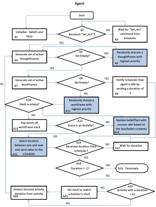
Figure 2.1 shows an architecture for resource-bounded agents demonstrating how BDI models will determine the actions of the agents. The diagram shows how per-ceptions form the agents’ beliefs about its environment, reasoning about these beliefs is performed and how to discover what implications they have. Means-end reasoning decides which plans are best used to complete the tasks. Desires are shown in this model in order to influence the option filtering process and also influence the deliber-ation process to produce intentions. Actions are decided once the options have been filtered, the list of intentions has been generated and the intentions are structured into plans. The model also shows that previously generated plans influence future plans yet to be created.
The BDI architecture does have its criticisms [69]: classical decision theorists and planning researchers question the necessity of all three mental attitudes while sociology and distributed artificial intelligence researchers question the adequacy of using only three.
Figure 2.2: Relating Brahms to the BDI architecture
i.e., if the agents beliefs match the guard condition of a workframe then that agent has a desire to execute this workframe. Plans are formed using the workframes and thoughtframes order by their priorities. Workframes will be executed in the descending order of their priority forming a plan of workframes, each workframe will complete a sub-task of activities with the aim of achieving the overall goal. The intentions of the agent are then the currently active workframes and thoughtframes which can be selected for execution.
The emphasis on the BDI agent architecture in this chapter is due to the likeness that Brahms has to this architecture. We would also like to point out that there are other alternative architectures for implementing agents. An example of such archi-tectures are deliberative, planning,Intelligent Resourse-bounded Machine Architecture
(IRMA), and reactive [87]. A deliberate agent has an explicitly represented, symbolic model of its environment. Decisions, such as the actions it will perform, are then made through some logical reasoning. An example of a planning agent architecture is STRIPS which takes a symbolic description of the world, a desired goal state, and a set of action descriptions. Pre- and post-conditions are used to execute actions in a specific order to achieve the goal. The IRMA architecture uses a symbolic data structures with a plan library and explicit representations for the beliefs, desires and intentions of the agent. A reasoner is then used to reason about the world and determine which plans may achieve the agent’s intentions. The IRMA architecture also has an opportunity analyser to monitor the environment to respond to events. A reactive agent architec-ture is one which does not use a central symbolic model of the world and does not use complex symbolic reasoning; the agents simply react to events that occur [87].
2.5
Chapter Summary
Chapter 3
Brahms
In this chapter we will discuss Brahms (Business Redesign Agent-based Holistic Model-ing System), a multi-agent modellModel-ing, simulation and development environment devised by Sierhuis [73] and subsequently developed at NASA Ames Research Center. We will describe the core aspects of Brahms and what they are for, along with some example code to illustrate how they are used. We also describe applications of Brahms, showing how and when it has been used. A comparison between Brahms and other agent pro-gramming languages is presented along with an explanation of why Brahms was chosen over these other languages.
3.1
Basic Anatomy of Brahms
3.1.1 Geography
In Brahms the model of the agent’s world is described using the geography model. Here the world is organised hierarchically, where an area can be conceptual (anareaDef, e.g., house, restaurant) or a physical location (area, e.g., 10 Downing Street). These area
and areaDef are used to form the hierarchy where: an area can be an instanceof an
areaDef; anareaDef canextend anotherareaDef; and an area can be partof another
area. The distance between two areas is described using a path, undefined paths are transitively calculated from the defined paths. Agents are assigned an initial location in the geography in their code. The following code shows a Brahms description of a city called Berkeley which has a university, a restaurant, a bank and a hall within the university. It also describes a path from the hall to the restaurant and the bank which infers a path from the bank to the restaurant.
area AtmGeography instanceof World { }
areadef University extends BaseAreaDef { }
areadef UniversityHall extends Building { }
areadef BankBranch extends Building { }
areadef Restaurant extends Building { }
area Berkeley instanceof City partof AtmGeography { } area UCB instanceof University partof Berkeley { }
area SouthHall instanceof UniversityHall partof UCB { }
area Telegraph Av 2405 instanceof Restaurant partof Berkeley { }
area Bancroft Av 77 instanceof BankBranch partof Berkeley { }
path StH to from RB {
area2: Telegraph Av 2405; distance: 400;
}
path StH to from_WF {
area1: SouthHall; area2: Bancroft Av 77; distance: 200;
}
3.1.2 Agents and Objects
Agents and objects are the core components of every Brahms simulation with agents modelling intelligent entities and objects modelling inanimate objects and sensors, etc. Objects have the same capabilities of agents except they react to external factors (facts, explained in section 3.1.3) and agents react based on their internal beliefs. Brahms provides an option for objects to switch from reacting to external factors to internal beliefs, but for our purposes we consider objects to react to external factors.
3.1.3 Attributes, Relations, Beliefs and Facts
Agents and objects can have their own personal attributes, relations and beliefs. At-tributes are characteristics of the agent such as their height, weight, power levels, etc. Attributes can be of type Boolean, String, Double or Integer. Relations are a form of attribute where the attribute’s ‘type’ is set of agents or objects (these sets are groups and classes, explained in Section 3.1.8). The relation then allows for a connection be-tween agents and objects, e.g.,public Account hasAccount would state that the current agent could have a relationship called ‘hasAccount’ with a set of agents (or objects) labelled ‘Account’. Beliefs and facts are all tied to attributes and relations, every be-lief and fact has to contain either an attribute or a relation, e.g., an agent could have the beliefAgentA hasAccount AccountAwhich would represent an ‘AgentA’ owning an account called ‘AccountA’. Beliefs and facts differ in that facts represent the real value the attribute or relation has and the beliefs represent what the agent believes it to be. Below is example code for declaring an agent with attributes, etc. note that the initial location on initialisation is defined using ‘location:’ and beliefs use the keyword ‘current’ to refer to the agent being defined by this code, e.g., ‘current.howHungry = 0’ represents the current agent’s belief that its attribute ‘howHungry’ has value 0 where ‘Bob.howHungry = 0’ represents this agent’s belief on Bob’s attribute ‘howHungry’.
agent Alex {
/*Assign the agent’s initial location*/ location: SouthHall;
attributes:
public double howHungry; public int perceivedtime; relations:
public Account hasAccount; initial_beliefs:
(current.perceivedtime = 0);
(current hasAccount Alex_Account); initial_facts:
(current.howHungry = 0); (current.perceivedtime = 0);
(current hasAccount Alex_Account);
3.1.4 Workframes and Thoughtframes
Workframes and thoughtframes represent the work and thought process in Brahms. A workframe contains a sequence of activities and belief updates which the agent/object will perform, whereas a thoughtframe only contains sequences of belief updates; a thoughtframe is simply a restricted workframe which is unable to process activities. Workframes can detect (usingdetectables) changes in the environment, update agent’s beliefs accordingly and then decide whether or not to continue executing. Essentially, workframes represent the work processes involved in completing a task and thought-frames represent the reasoning process upon the current beliefs, e.g.,
• Start workframe to go to the shops
• Rain causes a detectable to fire
• Agent now believes it is raining
• Workframe is suspended
• Thoughtframe is executed to decide that the agent needs a coat
3.1.5 Executing plans: Activities and Concludes
Agents are able to perform activities and concludes (belief/fact updates), these are executed via workframes and thoughtframes (which can update beliefs only, no fact updates or activities can be performed) which decide when they should be performed.
Primitive activities, move activities and communication activities are the three main types of activities.
Primitive activities are conceptual activities in the sense that they only spend simulation time, while the assigned name infers what the agent was doing, e.g.,primitive
activity ‘dig hole’ has a duration of 400 time units and no belief or fact updates are made. When assessing the simulation the name infers that the agent was digging a hole. To confirm a hole was dug the workframe would require a conclude to update the beliefs and the facts that a hole now exists. Brahms is a simulation framework, not an execution framework, so activities such asprimitive activities are used to subtract simulation time while an event is occurring.
Communication Activities are used for passing messages between agents, these com-munications are assigned a duration. Once this duration is over the beliefs of the other agents are updated corresponding to this communication, an agent however can only communicate beliefs it already has.
Below is an example of a workframe for eating using a simpleprimitive activity and a belief update. Note that a repeat variable has been set to true so that the workframe can be performed multiple times. The ‘when’ condition states the requirement for the workframe to activate, i.e., when the agent believes its hunger is greater than 10. The ‘do’ statement declares which activities and belief updates will be made; ‘eat()’ represents the activity to eat and conclude defines a belief update, i.e., that the agent’s hunger decreases by 3. Note that the belief update has ‘bc:100’ and ‘fc:0’, which represents a ‘belief certainty’ of 100% and ‘fact certainty’ of 0%, i.e., update the belief with a 100% probability and the fact with a 0% probability.
workframe wf_eat { repeat: true;
when(knownval(current.howHungry > 10)) do{
eat();
conclude((current.howHungry = current.howHungry - 3.00) , bc:100, fc:0);
} }
3.1.6 Detectables
Detectables are contained within workframes and can only be executed if their work-frame is currently active. They can detect changes in facts and can: abort, continue, complete or impasse the workframe. When a detectable is executed it imports the fact it “detected” into the agent’s belief base and then it either:
1. abort - deletes all elements from the workframe’s stack;
2. continue - carries on regardless;
3. complete - deletes only activities from the workframe’s stack; or
4. impasse - suspends the workframe until the detectable’s guard is no longer satis-fied
Below is an example of a workframe containing a detectable. The detectable states to ‘impasse’ (suspend) the workframe when it detects the agent’s thirst is greater than 10. The ‘when(whenever)’ means that the detectable can be activated at any time, a point of time in the simulation could be inserted here instead. The ‘dc:100’ represents a ‘detect certainty’ of 100%, meaning the detectable will always fire when it is active.
workframe wf_eat { repeat: true; detectables:
detect((current.howThirsty > 10), dc:100) then impasse;
}
when(knownval(current.howHungry > 10)) do{
eat();
conclude((current.howHungry = current.howHungry - 3.00) , bc:100, fc:0);
} }
3.1.7 Variables
Variables provide a method of quantification within Brahms. So, if there are multiple objects or agents which can match the specifications in a guard condition then the variable can either perform: forone- select one;foreach- work on all, one after another; or collectall - work on all at once. Below is an example of a workframe containing a variable to identify an object in the class of objects called ‘Cash’. The guard condition identifies which member of ‘Cash’ is to be selected, i.e., an object that the current agent has the relationship ‘hasCash’ with. The selected object is identified by the assigned name ‘cs’. A belief update in the workframe then changes the agent’s belief about the object’s attribute ‘amount’.
workframe wf_eat { repeat: true; variables:
forone(Cash) cs;
when(knownval(current.howHungry > 10) and knownval(current hasCash cs))
do{
eat();
conclude((current.howHungry = current.howHungry - 3.00) , bc:100, fc:0);
conclude((cs.amount = cs.amount - 10.00) , bc:100, fc:0);
} }
3.1.8 Groups and Classes
workframe ::= workframe workframe-name
{
{ display : ID.literal-string ; } { type : factframe | dataframe ; } { repeat : ID.truth-value ; } { priority : ID.unsigned ; } { variable-decl }
{ detectable-decl }
{ [ precondition-decl workframe-body-decl ] | workframe-body-decl }
}
Figure 3.1: BNF Grammer Representing Part of the Brahms Syntax Specification
are empty except for a location. This is to show that the agents can be entirely de-scribed in their superstructures but any individual information can be placed in their own personal sections of code.
group student{ attributes:
/*all attributes here*/ initial_beliefs:
/*all beliefs here*/ initial_facts:
/*all facts here*/ workframes:
/*all workframes here*/ thoughtframes:
/*all thoughtframes here*/ }
agent Alex memberof student{ location: SouthHall; }
agent Bob memberof student{ location: Telegraph_Av_2405; }
3.1.9 Brahms Syntax
Brahms has an expressive sophisticated syntax for creating systems, agents and ob-jects, the full syntax specification can be found in the appendix or the ‘agentisolutions’ website1. As an example Fig. 3.1 shows the definition of an agent’s workframe showing where variables, detectables and the main body of the workframe are placed. Guards are specified byprecondition-decl.
3.2
Applications
Brahms has been used in a variety of projects within NASA, from modelling the NYNEX telephone exchange in the early years to modelling the Mars Rover exploring the Victoria crater. Figure 3.2 provides an insight into where Brahms has been applied from 1992 up until 2008.
3.2.1 Extra-Vehicular Activities during Mars exploration
Bordini, Fisher and Sierhuis [9] describe a possible scenario of human-robot teamwork during a Mars exploration mission. An overview of the scenario can be found in Figure 3.3 and a more detailed description is found below.
During an Extra-Vehicular Activity (EVA) there are two surface astronauts and two EVA Robotic Assistants (ERA) assigned to explore a region of Mars. Both the astronauts and the ERAs have their own agenda to work to, but the ERAs also have the responsibility of ensuring that both the as-tronauts always have a network connection back to the habitat. The ERAs, like the humans, can be interrupted while performing their assigned tasks. When this happens the ERAs need to be able to handle this interruption without jeopardizing the astronauts, themselves or the mission.
ERAs can be assigned to “Team up” with an astronaut, becoming the as-tronauts personal agent (PA). The ERA’s tasks then involves additional functions such as “follow astronaut” and “astronaut watching”. The ERA also acts as a relay point for the connection back to the habitat for the astronaut. The ERA will therefore detect and inform an astronaut when they are moving out of range of communications with the habitat. Also if an astronaut calls to its PA for assistance the PA will have to suspend any activities it is performing and come to the astronaut’s aid. However if the PA is engaged in an activity which is more important than another ERA’s or another ERA is closer to the astronaut then the ERA can ask the other ERA to temporarily take over the role as the astronaut’s PA.
In summary, the ERAs assigned to work with the astronauts have to be com-pletely autonomous robots which can fulfil assigned tasks without human assistance. They need to be able to react to unpredictable situations such as loss in communications, as well as aiding other astronauts and robots when requested.
3.2.2 OCAMS
Figure 3.2: A history of Brahms applications
[image:31.612.142.500.444.660.2]involved with the current way of doing the work. In the system design and implemen-tation phases, this model of the human work practice behaviour was made part of the OCAMS multi-agent system, enabling the system to behave and make decisions as if it were an OCA officer. Here is a short scenario of how the OCAMS system is used in mission control:
The On-board Data File and Procedures Officer (ODF) sends a request to the OCAMS (personal) agent via their email system. The OCAMS agent parses the request and understands that the ODF has dropped a zip file to be up linked to the ISS on the common server. The OCAMS agent needs to identify the type of file that is being delivered and decide, based on this, what up link procedure needs to be executed. Having done so, the OCAMS agent chooses the procedure and starts executing it, as if it were an OCA officer. The OCAMS agent first transfers the file and performs a virus scan, and then continues to up-link the file to the correct folder on-board the ISS. The OCAMS agent applies the same procedure that an OCA officer would do.
The OCAMS system has been extended over three years [22]. With the latest release the OCAMS system will have completely taken over all routine tasks from the OCA officer, about 80% of the workload. Other flight controllers in mission control will interact with the OCAMS agent as if it were an OCA officer.
3.2.3 Teamwork In Brahms
Intentions in Brahms are represented by the guard conditions on workframes (plans of actions) and actions are represented by Brahms activities which spend simulation time, and in the case of move and communication activities they change locations and other agent’s beliefs as well. These intentions and actions can become joint through inheritance from a super class where the agents inherit team’s activities and work-frames. This isn’t ideal as different members of the groups will have different tasks to do within the team and different sub-goals. To model joint intentions the modeller has to specifically give agents individual workframes with guard conditions which are linked. Modelling joint activities is also difficult; agent’s workframes need to be syn-chronised using guard conditions and Brahms detectables (to detect when other team members are ready to start the joint activity) to ensure the agent’s operate together. Additional workframes then need to be used to conclude whether joint activities have been successful. The abstract nature of the Brahms activities does however alleviate some of the difficulties of modelling ajoint activity for example: a task for three agents picking an object up together only has the difficulty of ensuring that the agents start and finish their activities at the same time, the agents then conclude the object to be “picked up” after the simulation time elapses.
3.3
A Comparison with other Agent Programming
Languages
3.3.1 3APL
3APL agents use practical reasoning rules, which have been extended from the recur-sive rules of imperative programming, to monitor and revise agents’ goals [39]. 3APL incorporates features from both imperative and logic programming plus features which allow for a descriptions of agent oriented features, e.g., the querying of agents’ beliefs. 3APL also supports agents which have reflective capabilities related to their goals or plans provided by practical reasoning rules. Agents in 3APL follow these characteristics of intelligent agents:
• sophisticated internal mental state made up of beliefs, desires, plans, and inten-tions, which may change over time
• agents act pro-actively, i.e., goal-directed and respond to changes in a timely fashion
• agents have reflective or meta-level reasoning capabilities
A 3APL program allows a user to define the agent’scapabilities, beliefbase, rule-baseandgoalbase. Thecapabilitiesof an agent are the actions which it can perform such as put block a on block b. This is done using pre and post conditions with an action statement, e.g., a precondition on(a, table) would mean for this action to be performed then block a is on top of the table, with an action statementaOnb() (used to call the action) and post condition on(a, b) which states that after this action is performed block a will be on top of block b. The beliefbase is used to state what the agent believes, e.g., on(a, table) means the agent believes block a is on the table. The rulebase is used to describe the tasks the agent will complete, e.g., putAonB()
<−aOnb().tells the agent to perform the action aOnb(). Rules can contain multiple actions which the agent can perform in sequence. Finally in thegoalbaseare the list of rules which are to be performed such asputAonB(). Any additional requirements such as the environment or graphical interface, etc. are programmed using C and C++. An example of a 3APL program for the Blocks World problem is as follows:
CAPABILITIES
{on(a,table), on(b,table)} aOnb() {on(a,b)} BELIEFBASE
on(a,table). on(b,table). GOALBASE
putAonB(). RULEBASE
putAonB() <- aOnb().
For more information on 3APL see Hindriks et al. [39]
3.3.2 GOAL
facilitates the manipulation of an agent’s beliefs and goals in order to structure its decision-making. The language is based on common sense notions and basic practical reasoning. The main features of GOAL are [82]:
• Declarative beliefs; the agent’s initial beliefs at the start of the simulation
• Declarative goals; the agent’s initial goals
• Blind commitment strategy; drop goals only when they have been achieved
• Rule-based action selection; selection of actions based upon rules
• Policy-based intention modules; specific focusing on achieving a subset of the agent’s goals using only knowledge relevant to achieving those goals
• Communication at the knowledge level; inter-agent communication to exchange information, and coordinate actions
When programming in GOAL you are allowed to describe the multi-agent system using
environment,agentfilesandlaunchpolicytags. Theenvironmenttag uploads an environment from a Java file and theagentfilesallows uploading of GOAL agent files to the system. The launchpolicyis used to give rules on when the agent starts. For example:
environment{
"environment.jar" . }
agentfiles{
"agentA.goal" . "agentB.goal" . }
launchpolicy{
when entity@env do launch alex : agentA, bob : agentB . }
When defining an agent GOAL allows descriptions of the agent’sknowledge,beliefs
main BlocksWorldAgent {
knowledge{
block(a), block(b). on(X,Y).
}
beliefs{
on(a,table), on(b,table). }
goals{
on(a,b). }
program{
if a-goal(on(X,Y)) then move(X,Y).
if a-goal(on([X|T])) then move(X,table). }
action-spec{ move(X,Y) {
pre{ clear(X), clear(Y), on(X,Z) } post{ not(on(X,Z)), on(X,Y) } }
}
For more information on GOAL see [82]
3.3.3 AgentSpeak(L)/Jason
AgentSpeak(L) is an extension of logic programming for the BDI agent architecture, providing a framework for programming BDI agents [67]. An AgentSpeak(L) agent defines its beliefs as a set of ground (first-order) atomic formulae and uses a set of plans to form its plan library. AgentSpeak(L) contains two types of goals: achievement goals; atomic formulas prefixed with the ‘!’ operator and test goals; prefixed with the ‘?’ operator. Achievement goals describe a world state that the agent wants to achieve. Test goals are a test on whether the associated atomic formulae form one of the agent’s beliefs.
AgentSpeak(L) forms a reactive planning system where agents react to events re-lated to either changes in beliefs due to perception of the environment, or to changes in the agent’s goals due to the execution of plans. Plans are predefined and triggered by changes in beliefs and goals by either by addition ‘+’ or deletion ‘-’. An AgentSpeak(L) plan has a body, which is a sequence of basic actions (sub-goals) that the agent has to achieve (or test). Basic actions can be atomic operations the agent can perform to change the environment, or actions written as atomic formulae using a set of action symbols rather than predicate symbols.
[13]. Continuing with the Blocks World example, Jason allows simple declaration of be-liefs withonT op(a, table) to represent the agent believing block a is on top of the table. The plans are denoted using the @ symbol, e.g., @P1 would describe a plan called P1. In this plan a goal needs to be added with a condition, e.g., goal addition by +![on(a, b)] and condition :not onT op(a, b) stating block a must not be on top of block b. When these conditions are met a belief removal and addition are made;−onT op(a, table) to say that block a is no longer on the table and +onT op(a, b) to state that block a is now top of block b. An example of an AgentSpeak(L) Blocks World program is as follows:
/*Initial Beliefs*/ onTop(a,table). onTop(b,table). /*Plans*/
@P1
+![on(a,b)]
: not onTop(a,b) <- !putAonB(a,b); -onTop(a,table); +onTop(a,b);
3APL has been applied in main stream areas such as mobile computing [50], where an architecture 3APL-M has been developed to support the development of deliberative multi-agent systems in mobile computing devices. 3APL has also been used to for programming cognitive robots. For more information on AgentSpeak(L) and Jason see Bordini et al. [13]
3.3.4 Why Brahms
To decide which agent language/framework to use we drew up a list of requirements to help identify which language would best suit our needs. The list of requirements we generated are as follows:
1. allow for high level descriptions of agent activities with minimal coding
2. can show a distinct time line of events to demonstrate when activities occur
3. an embedded geographic model which requires no external code or environments
4. allow agents to perform human specific behaviour, such as:
(a) thinking about problems
(b) reasoning about the implications of beliefs and causality of actions (c) off task behaviour and multi-tasking
(d) making mistakes
(e) communicating with each other
(f) taking varied amounts of time to complete tasks
When considering these requirements it became clear that Brahms was the only language we could find to match these requirements. Brahms has the high level ab-stractions of activities all contained within a time line of events. It has a simple geographic syntax for describing the possible locations, the distance between them, their associations with each other and it is very simple to tell agents to move from location to location. Brahms was also developed for simulating humans, so it meets our human behaviour requirements. Brahms has also been used at NASA to simulate human behaviour for over 10 years.
Other agent languages considered were AgentSpeak(L) and Jason, 3APL, and Goal. These are all common and popular languages used to program agents, which is their primary function. Brahms on the other hand was developed to model both humans and machines at NASA [76, 73, 21]. Although representation of humans may be possible in all the above languages, it is only Brahms which has been specifically designed and used to model human behaviour. Brahms achieves this representation of humans by modelling the objects they use, the environment they are in, their thought and work processes, communication, and other concepts where humans and agents will typically collaborate. AgentSpeak(L) and Jason, 3APL, and Goal are focussed on the develop-ment and behaviour of the agents, including competitiveness and lack a framework for shared achievement [11]. However, it could be argued that any of these languages could be used for modelling humans, even though they have not been specifically designed to do so. This then leaves the issue of defending how accurate this representation of a human is, whereas with Brahms there are already papers and experiments demon-strating its use in modelling humans [76, 73, 21] and thereby we can safely assume it meets both requirements 4 and 5. Brahms also allows for a high level of abstraction, where capabilities of agents can be assumed. This high level of abstraction, which matches requirement 1, allows for easier modelling of humans because we can assume they can perform certain tasks, such as moving a simple object, without any difficul-ties. Whereas an agent centred approach like 3APL, GOAL and AgentSpeak(L) do not usually allow for such high level of abstraction, they require us to model every action. Activities in Brahms are inherently linked with time, meaning no extra coding is required which works towards meeting requirement 2. The other agent languages are more interested in the events themselves than the time they take to complete, although it is possible for them to represent this time it will require additional coding making the simulation more verbose. Brahms is also the only language which matches require-ment 3; an embedded graphical model. AgentSpeak(L), 3APL and GOAL all require the geographic models to be described in another language such as Java or C, making the simulations much more verbose and add an additional language to the verification process. Brahms’ graphical model is simple to program, has very little extra syntax and allows easy reference to these locations in the simulations.
Chapter 4
Formal Verification - Techniques
and Applications
The primary concern of this thesis is to perform formal verification of models of human-agent teamwork. In this chapter we discuss: what we mean by the term formal verifica-tion; why we wish to perform agent verificaverifica-tion; and which formal verification technique we use and why. The structure of this chapter is as follows:
• Formal Verification; here we explain what we mean by formal verification and formal operational semantics
• Model Checking; here we explain the formal verification technique model checking and the model checking tool Spin
• Other Formal Verification Techniques; here we briefly explain opposing verifica-tion techniques to model checking
• Agent Verification; here we explain how agent verification has previously per-formed on agent based systems
• Verification of Agent Languages; here we explain how verification has been per-formed on agent languages
4.1
Formal Verification
Formal verification represents a family of techniques aimed at assessing the correctness of a system design. These techniques have become very popular in hardware design since they can ensure 100% functional correctness of circuit designs [30]. For example, Kaivola and Narasimhan [46] describe the process they used to verify the floating-point multiplier in the Intel IA-32 Pentium microprocessor. Formal verification is always performed against a set of requirements, i.e., a specification. A formal specification is a concise mathematical description of the behaviour and properties of a system, stating what actions a system can take and what should (or should not) happen [51]. Informal specifications are inadequate for formal verification as they tend to be vague, improper, incomplete, hard to analyse and ambiguous. A multitude of formal languages and logics have been created in order to express as broad a range of properties as possible.
take off”. Safety is a concept which states something must never happen, e.g., “while performing manoeuvres in space, no doors can be opened”. Fairness is a concept used when multiple agents are employed; it states that each agent will fairly get the chance to perform an operation with no agent indefinitely occupying the resource. Formal languages may also need to be able to express properties concerning real-time dynamic systems, probabilistic systems and goal driven systems [11].
Essentially formal verification is a reachability test, testing whether a certain state can be achieved which does not satisfy the specification. Formal verification can how-ever be used to identify other faults in a system which are not part of the specification such as deadlock, livelock, race conditions and termination. Deadlock occurs for in-stance when a process will not release a shared resource that other processes are waiting to access and cannot progress any further until they access the resource. Livelock is similar to deadlock, such that no progress is made but no blocking occurs [63], e.g., one processor constantly flips a Boolean to true and in response another flips it back to false. There is no strict definitive definition of a race condition, however race con-ditions generally occur when different processes share a data source without explicit synchronization [60]. Termination analysis is simply a check to identify whether the program will always terminate, such as identifying any infinite loops. Termination is a difficult problem, also known as the halting-problem, and has been the subject to intensive research, for example, in [53, 33, 26].
The most popular approach to formal verification is model checking [27]. Model checking (see Chapter 4.2) creates a model of every single state achievable within a system, the transitions between these states, and also indicates which states are the possible initial states. Every single run (a sequence of state transitions from an initial point to an end point) is checked to ascertain whether or not a formal property holds. Model checking requires a finite model of the system, which we generate from the operational semantics, and the representation of a property to check in some logic.
4.1.1 Formal Operational Semantics
Formal operational semantics are interpretations of formal (mathematical) languages. They are used to precisely describe how a system will behave when executed. This is done by describing semantic rules which identify the possible types of states the system can be in and the ways the state can change when applying these rules. These semantic rules can be used to build a model of the system by applying the rules to the initial states of the system and then storing the resulting states in the model.
Formal operational semantics consist of a set of rules which govern how/when and what the system will do at a given time. These rules form a premise and a conclusion, rules with empty premises are axioms. Set theory and logical notations are used to describe both the premise and the conclusion. These notations are able to express the state of the system (e.g., a set of tuples and their values), describe the changes made to the data structures, and the resulting system after the changes have been made [84].
4.2
Model Checking
represented by a finite state machine (FSM), i.e., a directed graph consisting of vertices and edges. The model is exhaustively searched for reachable states where the specifica-tion fails [2]. Specificaspecifica-tions checked are unique to the systems requirements, typically of a qualitative (e.g., is the result OK?) and a timed nature (e.g., is task achieved within
x hours). General bad states such as deadlock, livelock and race conditions are also checked for. Figure 4.1 shows the model checking process, showing that the process starts with a description of the model and a desired property of the system. A model is then created from this description and a quick test is performed to check its accuracy. Meanwhile, the specification is formalised into a property specification language. The model checker then exhaustively checks every state to determine whether or not the property holds. If the property holds then the verification is complete, if not then an error trace through the model is produced to demonstrate how the property can be violated. Additionally, the model generated can be too large to be held in memory, requiring the model to be refined before verification can continue.
Baier and Katoen [2] detail a list of strengths and weaknesses of model checking:
1. Strengths
(a) Wide range of applications: embedded systems, software engineering and hardware design
(b) Supports partial verification, i.e., each property can be checked individually (c) Not vulnerable to the likelihood that an error is exposed
(d) Provides diagnostic information for debugging purposes (e) System does everything for the user making it simple to use (f) Increasing interest within industry
(g) Easily integrated into existing development cycles
(h) Verification performed is trustworthy due to its mathematical soundness
2. Weaknesses
(a) Unsuitable for data applications as they tend to cover infinite domains (b) Decidability can cause issues which can create infinite-state systems
(c) Finds design flaws not coding errors or fabrication faults (d) Checks only requirements which have been specified
(e) State-explosion problem may cause the system to run out of memory (f) Creating the model of the system requires expertise to abstract a small
enough system model and to convert the specifications into logical formulae (g) Results aren’t guaranteed to be correct, the model checker may contain its
own software defects
ability to return a Boolean true or false to a specification of the system. Decidability issues arise when models are either too large to hold in memory or the model loops infinitely. The model checker Spin has techniques to identify and remove infinite loops, and tools to keep models within memory limits. However there is always a possibil-ity that all available memory will become consumed leaving the model checker unable to return a result. We tried to avoid these memory issues by progressivly increasing non-determinism, since non-determinism is a key factor in state space explosions. By gradually increasing the non-determinism we can see at what point memory becomes an issue. 2(c) was not an issue since we are specifically looking for design flaws, coding issues can be resolved using the Brahms simulator. Model checking will only check for properties that it has specifically been asked to check (weakness 2(d)). This weak-ness was not a concern for us because we were only interested if our tool was able to correctly answer whether our specifications held or not. The model is generated automatically by the system we have created, eliminating the requirement of the user requiring the expertise to create the model, eliminating the issue 2(f). However, 2(f) also mentions that the user needs this expertise to convert the specifications into logical formulae. This means 2(f) is still an issue, the user needs to know how an agent’s belief is represented in the PROMELA translation and they must know how to convert the specification in to a PROMELA ‘Never Claim’. 2(g) may be an issue, it is extremely difficult to tell if the PROMELA translation exactly matches the Brahms framework. This means that an error found in a the verification may not be an error in Brahms or vice-versa. Also Brahms is a simulation itself, meaning a Brahms simulation may not accurately represent the situation it was trying to model.
4.2.1 Spin
The model checker used for the verification of the human-agent teamwork in this thesis was the Spin model checker [41]. In this section we describe Spin and the syntax for its input language PROMELA. Spin is a popular model checking tool designed to verify models of distributed software systems. Spin models concentrate on proving correct-ness ofprocess interactions and also attempt to abstract as much as possible from the internal sequential computations. Spin has a graphical front-end known as XSpin which allows users to define specifications of a high level model of concurrent systems. Spin accepts design specifications written in the verification language PROMELA (a Pro-cess Meta Language). The PROMELA language is very similar to ordinary program-ming languages, but it has the added capability of handling certain non-deterministic constructs [37]. This high level specification of the systems is tested via interactive simulations to assure a basic level of confidence in the model. The high level model is then optimised using reduction algorithms. The optimised model is used to verify the system. If any counterexamples to the specification are found during verification then they are passed through the high level model to inspect this example in greater detail. Figure 4.2 shows Holzmann’s [41] diagram to illustrate the structure of Spin. The diagram shows thatPROMELA, along with a property in Linear Temporal Logic, can be parsed in order to find: 1) syntax errors 2) produce a simulation or 3) generate a finite state machine for verification. For model checking the state machine is opti-mised and on-the-fly model checking is performed. On-the-fly model checking refers to checking the specification while generating the model. Any counter-examples produced are related to simulation runs.
![Figure 2.1: An architecture for resource-bounded agents [18]](https://thumb-us.123doks.com/thumbv2/123dok_us/8074561.227441/21.612.191.450.212.559/figure-an-architecture-for-resource-bounded-agents.webp)

![Figure 4.1: The model checking process [2]](https://thumb-us.123doks.com/thumbv2/123dok_us/8074561.227441/41.612.145.504.174.600/figure-the-model-checking-process.webp)
![Figure 4.2: Structure of the Spin model checker [41]](https://thumb-us.123doks.com/thumbv2/123dok_us/8074561.227441/43.612.208.412.295.550/figure-structure-spin-model-checker.webp)

![Figure 4.5: Overview of the AIL Architecture [28]](https://thumb-us.123doks.com/thumbv2/123dok_us/8074561.227441/51.612.224.421.76.182/figure-overview-of-the-ail-architecture.webp)