Numerical Modelling of Multilayered Coatings – Latest
Developments and Applications
Deqiang Yin
1,2,*, Zhenhai Xu
2, Jiling Feng
3, and Yi Qin
2 1School of Manufacturing Science and Engineering, Sichuan University, Chengdu, P.R. China
2
Department of Design, Manufacture and Engineering Management, University of Strathclyde, Glasgow G1 1XQ, Scotland, UK
3
School of Engineering, Manchester Metropolitan University, Manchester, M15 6BH, UK
Received 8 May 2014 / Accepted 12 July 2014
Abstract –The remarkable mechanical properties of multilayered coatings, such as super-hardness, excellent resis-tance against cracking, low wear-rate and high thermal-stability, are due to their unique interfacial structures and defor-mation mechanisms at the nanometer scale. The multilayered coating process itself is a typical multi-scale phenomenon. The modelling of multilayered coatings has become an important topic in research recently, largely due to the recent progress that has been made in the numerical modelling of materials and structures at different length-scales as well as the improved effectiveness achieved in linking such progress in numerical modelling to enable multi-scale modelling. In this paper, numerical modelling for the analysis of multilayered coatings at individual length-scales: Continuum, Molecular and Nano-scale, is reviewed, along with that at multi-scale modelling. Examples are pre-sented showing numerical models obtained using: the Finite Element Method (FEM), Molecular Dynamics (MD), First-principles calculations and Multi-scale modelling, are presented. Their relative limitations are discussed and chal-lenges to their future work highlighted.
Key words:Numerical modelling, Multilayered coatings, Multiscale modelling, Transition metal nitrides
1. Introduction
Multilayered coatings, especially with transition metal nitrides at nanoscale, are currently subjects to intensive research because of their potential for a wide range of technological applications [1, 2] and also because they are, fundamentally, of scientific importance [3,4]. Figure 1shows the representa-tive structures of multilayered coatings (a) TiN/CrN and (b) TiAlN/VN. Indeed, the interest in nitride coatings is two-fold: transition metal nitrides, which are well classified as refractory compounds, exhibit unusual physical and mechanical properties such as extreme hardness, high thermal- and chemi-cal-stability, good corrosion resistance, and low, stable friction under even dry contact conditions [5–9]. These intriguing prop-erties render them applicable for many uses, for instance, in relation to: engineering tools, magnetic and electric compo-nents, superconducting devices, etc., whilst periodic coating of these nitrides in the nano-scale dimension [10,11] onto such tools components and devices can enhance most, if not all, of their functions to a level that none of their individual constitu-ents can ever match [12]. A representative example is that the
multilayered TiN/VN superlattice, produced by alternating depositions of its two host mononitrides, which reaches a hard-ness value as high as 56 GPa [13–15], this being much higher than that of either of its host coating alone. Moreover, multilay-ered coatings enable the design of constituted materials with desired properties. For example, of all the transition metal nitrides, TiN is the most commonly used nitride. It is of interest largely because TiN is hard and wear-resistant, has a bright golden color, and can be coated onto many engineering materi-als. However although TiN/VN multilayered coatings exhibit the highest hardness, their widespread applications are currently limited by their propensity to be oxidized, especially at a high temperature, which degrades mechanical properties of TiN/VN multilayered coatings [16–19]. To avoid this problem, multilay-ered coatings TiN/CrN or TiN/AlN lead to improved thermal stability and excellent oxidation resistance with no notable loss in hardness [20–26]. Transmission electron microscopy (TEM) studies [27] have attributed the property improvement to a thin Cr2O3 layer that can suppress the formation of oxides
and voids.
Apart from the sophisticated applications in tooling industry and other engineered components, due to their excellent mechanical properties, especially the hardness, origin from *e-mail:[email protected]
DOI:10.1051/mfreview/2014008
Available online at: http://mfr.edp-open.org
This is an Open Access article distributed under the terms of the Creative Commons Attribution License (http://creativecommons.org/licenses/by/4.0), which permits unrestricted use, distribution, and reproduction in any medium, provided the original work is properly cited.
the nature of transition metal nitrides, multilayered coatings, composed of other functional constituents, are also used in the fields such as optical filters [31–40], magnetic storage [41,42], sensors and microelectronics [43–46]. For instances, Wang et al. [32] fabricated a TiO2/SiO2multilayered optical
fil-ters with graded refractive index profiles, deposited on glass (BK7) and Si(1 0 0) substrates simultaneously and sequentially, by helicon plasma sputtering at room temperature, and found that the measured transmittance spectrum exhibited a reflec-tance of 99.8% at a central wavelength of 730 nm and high transmittance over the wavelength region outside of the reflected band, as a result of the suppression of the sidelobes. Furthermore, Chhajed et al. [35] designed and produced a nano-structured multilayered tailored-refractive-index antireflection coatings on a glass substrate by using low-refractive-index sil-ica, and reported that the measured average optical transmit-tance between 1 000 and 2 000 nm is improved from 92.6 to 99.3% at normal incidence. Moreover, Raut et al.[39] described different types of the Anti-Reflective Coatings (ARCs) in greater detail and illustrated the state-of-the-art fabrication techniques. Louis et al. [40] also gave an overview on the progress in the thin film and surface physics involved in multilayered systems with nanometer scale periodicity, wherein a special attention was given to the development of thin diffu-sion barrier layers between the materials in the multilayered coatings to enhance the optical contrast and to reduce the inter-diffusion.
From the above brief description, it can be seen that the multilayered coatings could be tailored/designed based on the choice of individual constituents for a particular multilayered systems, and these intriguing advantages make them applicable for many uses.
Improvements in mechanical properties due to introducing multilayered coatings, encompassing post-processing behavior, have attracted many studies from both experimental and theo-retical. Experimentally, the studies have covered the effects of: (i) preliminary treatment of the substrates; (ii) various kinds of material combination, as well as the thickness ratio of neighboring layers; (iii) post-processing, and evaluation of the mechanical, thermal, and magnetic properties via bending, buckling, nano-indentation, scratching, tensile test, acidic corrosion, high-temperature test, etc. [47, 48]. For instance,
understanding of the origin of property improvement through multilayered coatings is twofold: on one hand, it is attributed to the interfaces in multilayered coatings. Nordin et al. [49] reported a significant slowdown of corrosion for the TiN/CrN multilayered coatings because the oxidation is found to be almost inversely proportional to the number of interfaces in the multilayered coatings, as is confirmed in other previous works [50,51]. On the other hand, it is ascribed to the residual stress present in the multilayered coatings [52]. Mendibide et al. [28–30] successfully deposited TiN/CrN onto the tool steel and investigated the effect of residual stress [53], finding, by trans-mission electron microscopy (TEM) and synchrotron analysis, that the wear resistance of TiN/CrN is improved due to the mode shift of crack propagation induced by the fluctuating residual stress field across the multilayered coatings. In addi-tion, they claimed that interfaces in the multilayered coatings also play a crucial role in improving the refractory properties and wear resistance. More detailed information of multilayered coatings could be found in the literatures, such as references [54–57]. Correspondingly, various theoretical models have also been developed to explore the mechanisms for the enhanced chemical and mechanical properties of multilayered coatings. However, a better understanding of the underlying mechanisms of multilayered coatings still requires a more novel and more applicable model. In this paper, recent advances in the numer-ical modelling of multilayered coatings are critnumer-ically reviewed with a reference to modelling at length-scales and the numerical methods used.
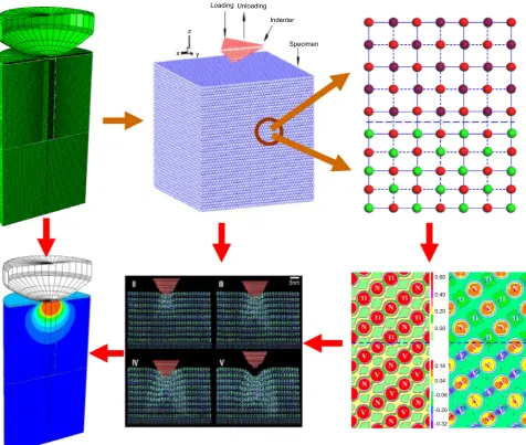
[image:2.595.124.463.75.224.2]Evidently, one of the notable characteristics of multilayered coatings is that the thickness of individual layer is in the nano-scale, that is to say, it is generally from several nanometers to tens of nanometers while the thickness of the whole system may be in micrometers to millimeters, inducing an abundance of numerical simulations at different scales. Based on the scale applied, the existing numerical models can be generally classi-fied into three categories: continuum models, molecular dynam-ics models, and nano-scale models, as illustrated in Figure 2. There are also some coupled models or methods combining two of them, such as the quasi-continuum (QC) method, which is a mixed continuum and atomistic approach for simulating the mechanical response of polycrystalline materials. Importantly, there are two basic requirements for building a theoretical
model. One is that the model has to be ‘‘big’’ enough to repre-sent the behaviours/properties of the multilayered coating sys-tem studied, and another is that the size of model is limited by the computational power. Consequently, a theoretical model may only be able to consider a thin layer containing the coat-ings-substrate system, composed of single, duplex or a limited number of phases.
2. Continuum models
[image:3.595.60.537.73.476.2]Intuitively, the structure of super-hard multilayered coatings at the nanometer scale is still a continuum [58]. Thus, a natural attempt to model multilayered coatings is based on conven-tional fracture mechanics and continuum mechanics scaled down to the dimension of nano-layered. A representative volume element (RVE) for a constitutive model is shown in
[image:3.595.311.540.513.717.2]Figure 3. It is worth noting that for RVE, the layers of two phases are parallel to each other, and arranged alternatively with perfect bonds, and with a constant interlayer spacing. Thex1x2
Figure 3. Schematic illustration of an RVE of a multilayered coating.
x y
z
Loading Unloading
Indenter
Specimen
0.60
0.40
0.20
0.00
0.16
0.04
-0.08
-0.20
-0.32
plane of the coordinate frame is parallel to the layers, and thex3
axis is perpendicular to the layers. If the thickness of each layer is assumed to be sufficiently small, compared to its in-plane size, the variation of both stress and strain within a phase can be neglected. The thicknesshis the modulation period of mul-tilayered coatings. Consequently, the numerical methods applied in these models include mostly, Finite-Element Method (FEM) [59], Finite Difference Method (FDM) and the Boundary-Element Method (BEM) [60,61]. Typical examples of a multi-layered coating, simulated mostly with FEM, are presented in this section, containing various elastic and elastic-plastic mate-rial properties, normal and tangential loading conditions, a hard coating/functionally graded substrate system, etc. Finally, a FEM model with cohesive zone modeling, used for the predic-tion of the formapredic-tion and propagapredic-tion of micro-cracks under indentation, is taken as an example of a general procedure for the FE simulation of multilayered coatings.
FEM can be used to simulate the behavior of multilayered coatings under either (nano-) indentation or subjected to a scratch test, mainly concerning:
1. Stress distribution. For instance, Djabella and Arnell [62] used a FEM to investigate the contact stresses during the process of elastic compression on coating/substrate sys-tems consisting of a high modulus surface coating on a relatively low modulus substrate wherein two pressure distributions were imposed to consider those arising dur-ing the Herzian indentation of a homogeneous elastic half-space by spherical and cylindrical indenters. They found that the stresses of both the outer surface of the coating and the coating-substrate interface are compli-cated functions of (a) the ratio of the Young moduli of the coating and substrate and (b) the ratio of the coating thickness to the contact halfwidth; and that the stresses which could be responsible for coating failure cannot simultaneously be minimized by appropriate choice of variable. Further, Stephens et al. [63] analyzed initial yielding behavior due to the indentation and friction pro-cess between an elastic cylindrical surface and a hard coating/functionally graded substrate system where a thin hard DLC film deposited on a soft Ti-6Al-4V alloy sub-strate is considered as a model system with consideration of two functional gradient substrate conditions: (a) a gra-dient in yield strength and (b) a gragra-dient in elastic mod-ulus. They found that in both cases, appropriate gradients result in significant benefit to the reliability of the coated system, compared to the case of an ungraded substrate. Furthermore, Bouzakis et al. [64] introduced a continuous FEM simulation of the nano-indentation hardness test in order to describe the coating’s elastic and plastic deformation and herewith, and thereby to extract, precisely and independently of the indentation load, the coating stress-strain curve. Similarly, Tan and Shen [65] employed FEM to examine the relationship between indentation hardness and overall yield strength of multilayered materials, and found that the indentation-derived strength consistently underestimates the composite yield strength within the scope of the
continuum-based approach. Additionally, Zhao et al. [66] simulated nano-indentation-induced deformation in TiSiN-based multilayered coatings by means of FEM, and quantified stress distributions under moderate inden-tation loading in the structure with particular emphasis on the relationship between stress concentrations and crack initiation. The results showed that structural layering can be used to modify the stress distribution and to lower the overall stress level within the coating. In the case of radial tensile stresses at the coating/substrate interface, a reduction of ~50% was achieved through layering. 2. Hardness measurement. FEM has been widely used to
simulate elastic and plastic deformations beneath a pointed indenter, hardness measurement with a sharp pyramidal indenter, such as Berkovich or Vickers, is one of the most complex mechanical problems, due to the 3D dimensional phenomenon associated with elastic and plastic deformations with large strain fields. As is well known, FEM is used to extract the true hardness of thin coatings, from the composite hardness measure-ments, based on the assumption that the film and sub-strate behavior can be modeled with a bilinear law. However, Pelletier et al. [67] showed that the bilinear model does not define correctly the strain hardening, resulting in an overestimation of the yield stress or one need to adjust the target modulus at each indentation depth.
TiAlN-nano-coating and AlCrN coated tools in finish-cutting conditions, and showed that the temperature at the tool-chip can be stable and as high as 800 °C when using TiAlN-based coated tool. Additionally, the pres-ence of the coating layer creates an additional thermal resistance between workpiece and the tool, slightly low-ering temperature at the substrate. Holmberg et al. [75] carried out a micro-scale finite-element method modelling and stress simulation of a 2 lm TiN-coated steel surface and showed a reduction of the generated tensile buckling stresses in front of the sliding tip, when compressive residual stress of 1 GPa was considered in the model. 4. Residual Stress. FEM can also be used to study the
resid-ual stress caused by the different thermal expansion coef-ficients between two phases of multilayered coatings during thermal cyclic loading or a manufacturing process. For instance, Ng and Gan [76] presented finite-element coupled heat transfer and elastic-plastic thermal stress analysis using a general purpose of commercial FEM to simulate the in-situ residual stress generation during plasma spraying of duplex thermal barrier coatings. They also proposed a simple method by post-deposition treat-ment to effectively reduce the residual stress level. Sarikaya and Celik [77] studied the thermal evolution of MgO-ZrO2/NiCrAlY coatings on Ni metal and AlSi
alloy substrates, using the finite-element method, and showed that stress concentration was at higher levels in the coatings with AlSi substrate than that when with Ni, and that the larger residual stress was obtained with an increase of the coating thickness. Similarly, Teixeira [52,78] presented a FEM model of the residual stress dis-tribution with a layered metal-ceramic composite coating, based on the difference between the coefficients of ther-mal expansion of the neighboring layers, obtaining an analytical expression of the residual stress. They also dis-cussed the failure modes of a thin coating under residual stress as: (a) delamination (coating under tensile stress and ‘‘weak’’ interface, i.e. low adherence); (b) perpendic-ular micro-cracking (coating under tensile stress and a ‘‘strong’’ interface); and (c) buckling and spalling (coat-ing under compressive stress). Moreover, Hsueh and Lee [79] also calculated the elastic thermal residual stress in thermal-barrier coating, which consisted of a substrate, a graded bond coat, and a top coat, with the origin of dif-ferent coefficients of thermal expansion [80]. Liu et al. [81] investigated the effect of a system composed of Al2O3and SiC on 316L stainless on the residual stress
developed in the composite coatings, and showed that the presence of the graded properties and the composi-tions within the coating did lead to the reduction of the stress discontinuity at the interfaces between the coating and the substrate whereas the magnitudes of the residual stresses on the coating surface and at the coating/substrate interface were dependent on the Al2O3and SiC coating
thickness. Using FEM, Sayman et al. [82] carried out a transient thermal analysis in WC-Co/Cr-Ni multilayered coatings deposited on a 316L steel substrate during the cooling process from 1 273 K to room temperature.
Similarly, Toparli et al. [83] determined the thermal resid-ual stresses in WC-Co/Ni-Al coating layers deposited on 316L stainless steel substrates, developed during and after thermal cycling, showing that the calculated tensile stresses were higher than the compressive stresses. Recently, Far et al.[84] developed a FEM model to eval-uate the stress induced by the thermal cycle in a typical plasma-sprayed thermal-barrier coating system, taking into account the effect of thermal and mechanical proper-ties, morphology of the top-coat/bond-coat interface, and oxidation on the local stresses that are responsible for the micro-crack nucleation during cooling, especially near to the metal/ceramic interface.
5. Other applications. Apart from the applications described above, FEM has also been used for the following partic-ular applications. For examples, Pan et al. [85] compared the sliding contacts of gradient layer, sandwich layer and ordinary multilayered coatings, subjected to a similar surface load and under elastic-plastic deformations, and found that the positive gradient layer coating can improve the stress and strain fields near the layer-substrate inter-face, and in the substrate, meanwhile, the sandwich layer coating can greatly reduce the maximum shear stress on the interface of the layer-substrate and the stress at the crack tip. Conversely, the stress and strain distributions of the ordinary layer have not evidently been improved, compared to those of the single layer. Their work pro-vided a useful reference for the selection and design of coatings. Furthermore, Bemporad et al. [86] designed the thickness and Ti distribution in multilayered Ti/TiN coatings with FEM-based optimization leading to a sig-nificant increase (45%) in adhesion between the layers and the WC-Co interlayer (Ti-6Al-4V substrate) and load bearing capacity of the coated system, compared to monolayered TiN, without reduction in superficial hard-ness and in the load bearing capacity. Lakkaraju et al. [87] modeled multilayer Cr/CrN thin films and optimized them to have effective ‘‘load support’’ by the films on stiff A2 steel and compliant 2024-Al substrates. The effi-ciency of several optimization algorithms such as genetic algorithms and gradient based routines was discussed and the preliminary results were compared to the results of pin-on-disk wear test results of empirically designed coatings. Similarly, Gorishnyy et al. [88] built two-dimensional models, utilizing FEM, for single layer CrN and Cr2N films and for a number of multilayer
combinations of Cr, CrN and Cr2N layer, aiming at
devel-oping an approach for the design of multilayer coatings with enhanced toughness to fracture and improved adhe-sion for wear-resistant applications.
allows for the parameters to be changed easily during a series-analysis. Combined with the capability of the prediction of cracking of the coatings, the developed method/model provides an efficient way for investigating the effects of these parameters on the behavior of multi-layered systems. It was demonstrated with analysis of the coated tool-steel (H11) for: (a) a substrate without being pre-heat-treated and (b) two substrates with a shallow and a deep hardened-case respectively (both are treated by plasma-nitriding). The results showed that the case-hardening of a substrate has a significant influence on the performance of the surface system with coating, especially on its load-bearing capacity and on its the resistance to the devel-opment of cracks in the coating.
It is worthy of noting that in reference [89], a bilinear cohe-sive-zone model was employed to simulate the development of cracks in the coating of a tool subjected to indentation, the general procedure being as follows:
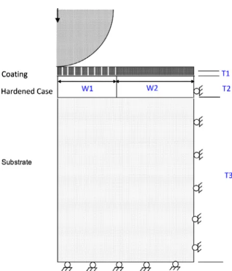
(a) Definition of the geometry model and meshing scheme. In this step, model dimensions and meshing scheme are established. Figure 4 shows the structure of a multi-layered system indented by a spherical indenter and the corresponding geometry. Based on the assumption of an axi-symmetric problem, only one half of this model is shown. The axi-symmetric model is made up of five blocks including: a central and an outer coating layer; a central and an outer hardened case; and the substrate, where: W1 and W2 indicate the width of the central and the outer parts respectively; and T1, T2 and T3 indi-cate the thickness of the coating, the hardened case and the substrate, respectively.
(b) Materials definition. Any number of materials can be defined for the simulation. Each material is assigned a name. A region in the model can be associated with a particular material through the assignment of its section properties that refer to the material’s name.
(c) Definition of the contact and boundary conditions. In this step, the surfaces and interactions between surfaces are created. Boundary conditions, which can be recognized as the interactions between the system and environment, also need to be defined.
(d) Definition of cohesive elements. The cohesive elements, combined with the FE, using a traction-separation rela-tion in order to describe the interface as a continuum of coatings and the host, are defined in order to simulate the formation and propagation of cracks under indenta-tion. Several traction laws have, to-date, been applied for this kind of analysis, either in a form of exponen-tial relationship [90, 91] or in a bilinear relationship [92–94] between the stress and the displacement. (e) Validation of the FE model. The FE model is validated
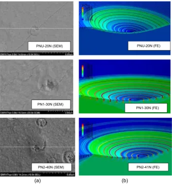
through a series of indentation tests. A comparison of the experimental results with finite-element results is shown inFigure 5. It should be mentioned that the adhe-sion energy values used in Cohesive-zone modelling is critical and that these can be obtained either from calcu-lations based on experimental data or by means of com-putations based on Molecular Dynamics or First principles calculation based on high-precision density functional theory (DFT) [95].
(f) FE analysis. After validation of the model has been done, the model can be used to analyse cases of interest. The analysis can be re-activated for a different set of input-variables, simply by re-setting values of these vari-ables in an input file, without need to modify the model through using a CAD/CAE software.
[image:6.595.50.278.67.333.2]The project ‘‘Multi-scale modelling for the design and analysis of multi-layered engineering surface systems (M3-2S)’’ was undertaken jointly by 11 international partners, funded through the 7th European Framework Programme, wherein the overall objective of the project was to establish integrated, generic, robust multi-scale modelling techniques, based on atomic FE(nano), crystal plasticity FE (micro) and continuum mechanics FE (macro) modelling. For examples, Leopold et al. [96] developed an advanced adaptive FEM software (AAFEM) for the coating-substrate simulation of superlattice TiN/CrN-coatings; Zhuang et al. [97] developed an user-subroutine to implement a multi-axial, continuum damage mechanics (CDM)-based constitutive model into a commercial FE code, and carried out a series of investigations into the TiN/Cu system; Perucca et al. [98] demonstrated per-formance of the TiN and TiN/CrN nanoscale multilayered coatings on WC cutting inserts for machining GJL250 cast iron. It was shown that the nano-structured TiN coatings, fol-lowed by multilayered coatings, have much better perfor-mance, and the FE simulation showed a good agreement between the measured cutting-force and the simulated one; and Karimpour et al. [99] presented an inverse method for
identifying properties of the material constituents in their mul-tilayered coatings, combining FE simulations and indentation data, which is extensible to the analysis of multilayered coat-ings containing any number of constituents.
3. Molecular dynamics
It is well known that the mechanical behavior of a material with a very small volume differs from that which is typically observed for that with a large volume. Analysis of such a phe-nomenon at the micro-scale has been largely with Molecular Dynamics (MD) Simulation. It is worth noting that there are two basic assumptions made in standard MD simulations [100–102]: (1) Molecules of atoms are described as a system of interacting material points whose motion is decided dynamically by the potential, and (2) No mass changes in the system, i.e., the number of atoms in the system remain the same during the pro-cess. Similarly, in continuum models, MD has also been used for the analysis of indentation. For instance, Saraev and Miller [103] used MD simulations to elucidate details of plastic deforma-tion and the underlying deformadeforma-tion mechanisms during the nano-indentation of thin copper films with epitaxial nickel
coatings, and observed several deformation mechanisms, such as dislocation pile-up at the interface, dislocation cross-slip and movement of misfit dislocations. Similarly, Cao et al. [104] per-formed MD simulations of indentation, following a nano-scratching process, to investigate the mechanical and tribological properties of Ni/Al multilayer with a semi-coherent interface. The results showed that the indentation hardness of Ni/Al multi-layers is larger than that of a pure Ni thin film, and the remarkable strength of Ni/Al multilayered coatings is due to the semi-coherent interface which acts as a barrier to glide of dislocations during nanoindentation process. Furthermore, Fang and Wu [105] carried out a MD simulation to study effects of indention defor-mation, contact and adhesion on Al, Ni, and Al/Ni multilayered films. The results showed that when the indention depth of the sample increased, the maximum load, plastic energy, and adhe-sion increased. Shan et al. [106] studied the effect of a single twin boundary parallel to the indented surface on nanoindentation of Ag(1 1 1) films, and showed that the twin boundary has little influence on the elastic modulus of films. The load for the initial yield is observably reduced when the twin boundary is very near the indented surface due to the nucleation of the glissile disloca-tions on the slip plane parallel to the surface, rather than the for-mation of the tetrahedral sessile lock when nano-indentation on PN1-30N (SEM)
PN1-30N (FE)
PN2-41N (FE) PN2-40N (SEM)
PNU-20N (FE) PNU-20N (SEM)
[image:7.595.128.468.72.439.2](a) (b)
the perfect film. Moreover, they also showed other two com-monly-use functions of MD simulation in multilayered coatings:
(a) The tension of multilayered coatings [107]. For instance, mechanical behavior, dislocation nucleation and develop-ment, and evolution of an interface in Cu/Ag bilayer films during equal biaxial tension were studied using MD simula-tions. The results showed that dislocations are prone to nucleate at the interface of Cu/Ag bilayer film, and then propagate towards the free surface. The deformational defects consist of partial dislocations and intrinsic stacking faults, accompanying some extrinsic stacking faults and stacking fault tetrahedral which just occur at the interface and propagate in the Cu layer.
(b) Interface-structure formation [108]. Assisted with MD simulations with EAM potential, the formation of the interface of a Cu/Ag bilayer during sputtering was stud-ied. The method provides a notable way to elucidate the mechanism of interfacial formation, which plays a dom-inant role in controlling the mechanical properties of multilayered coatings.
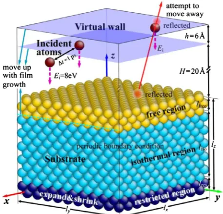
A MD model of atomic deposition is shown inFigure 6. Four growth cases, including Ag/Cu(1 1 1), Cu/Ag(1 1 1), Ag/Cu(0 0 1) and Cu/Ag(0 0 1), were simulated under the deposition ofEi= 8 eV (the kinetic energy for incident atoms) andT= 300 K. The results showed that the first- deposited Ag layer grows on the Cu substrate by the layer mode, while the firs deposited Cu layer grows on the Ag substrate by the island mode, determined by the surface energies of the film and substrate.
4. Nano-scale modelling
At the atomistic scale, the first-principles calculation based on the high-precision density functional theory (DFT) [92],
is a sophisticated way to provide insight into the bonding configuration, interfacial structure, and electronic properties, which are difficult to obtain by experiments alone at such a scale, as well as the behavior during the ideal tensile/shear process.
Four steps are usually used for building a reasonable inter-facial model for multilayered coatings at the atomic scale [109]:
(a) Firstly, the preferred textures of each individual layer for the composited system are made sure, e.g. from experi-mental observations [110];
(b) Secondly, perform convergence calculations on the sur-face energy with respect to slab thickness are performed to ensure that individual layers of the multilayered coat-ings model are thick enough to exhibitbulk-likeinteriors. Taking the TiN/VN interface for examples, the surface energy, (r0
s) under the condition that the chemical poten-tial of respective element equals its bulk total energy can be expressed as follows [111]:
r0
s ¼ 1 2A E
total
slab MNEbulkXN E
bulk
X ðMXMNÞ
; ð1Þ
whereEtotalslab,E bulk
XN andE
bulk
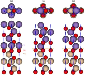
X represent the total energies of a formula unit of a slab (TiN or VN), XN bulk, and X bulk (X= Ti or V), respectively, andMXandMNdenote the number ofXandNatoms andAis the surface area. As illustrated in Figures 7b–7g, there are, in principle, six possible terminations for either TiN or VN.
(c) Thirdly, considering the interfacial stacking sequences and various terminations of individual surface, a series of possible candidate models could be constructed. As shown in Figure 8, there are three stacking sequences for TiN/VN multilayered coatings.
(d) Finally, theadhesion energy(Wad), a key quantity in
pre-dicting the adhesive properties of an interface can be cal-culated to determine the most energetically stale surface, from [112,113]:
Wad
ETINþEVNEIF
ð Þ
A ; ð2Þ
whereETIN,EVN, andEIFare the total energy of isolated
TiN, VN slab, and their interface, respectively, andAis the interface area. Two steps were taken to estimate the Wadvalues. Total energies were first calculated for a
ser-ies of separations as the two rigid slabs were approach-ing increasapproach-ingly closer from a large initial separation. Consequently, the calculated energies behaved like a parabola, passing through a minimum at the equilibrium separation. Theunrelaxed Wadwas obtained by
comput-ing the energy difference between the interface at the equilibrium state and the unrelaxed isolated slabs. Then, each isolated slab as well as the interfacial slab was allowed to optimize fully, yielding an estimation of the relaxedvalue ofWad.
[image:8.595.50.279.74.293.2]More importantly, first-principles calculations can be employed to investigate original mechanisms from atomic
stacking sequences, bonding properties/interactions between neighboring atoms, etc., at the atomistic scale, due to the fact that the atom is the minimum element for the composited systems. For instance, the two mostly addressed topics for multilay-ered coatings are Template effect and Superhard mechanism.
For ‘‘Template effect’’, the metastable phase can form in multilayered coatings due to the template effect, which means that the crystal structure of the newly deposited layer is under a strong influent of the underlying multilayer system. In this way, the newly deposited layer may crystalline in ametastable structure by forming
(c) (b)
(a)
Ti
N1
[image:9.595.58.535.73.267.2]V1
Figure 8. Schematic plots of (a) OT, (b) SL, and (c) TL stacking sequences. Upper part shows top view and lower part side view. The interfaces between N1-terminated VN and Ti-terminated TiN are given only. For top views, only the Ti layer nearest to the interface is shown for clarity. The view direction for bottom panels is along [11 0] and the location of interface is marked with horizontal dotted lines. The top and bottom portions of the interface have been omitted.
(b)
N1
(c)
V1
(d)
(111)
N2
(e)
V2
(f)
N3
(g)
V3 V2
N1
N3
V1
V3
N2
[image:9.595.126.467.323.624.2](a)
a coherent interface with the rest of the multilayer structure. Such a mechanism often leads to strengthening the coatings and thus is desirable. Taking the representative multilayered coatings TiN/ AlN for example, Chawla et al. [114] combined ab initio methods and the finite element (ABAQUS) to study and predict the equilibrium critical thickness up to which the metastable cubic (c) AlN phase is energetically favoured to the stable wurzite(w) variant in TiN/AlN and CrN/AlN bi-layer system. And Zhang and Veprek [115] selected deliberately a couple of representative transition metal (AlN included) as interfacial layers in TiN-based heterostruc-tures, and investigated the thermal stability using first-principles molecular dynamics. The results showed that one-monolayer-thick pseudomorphically stabilized interfacial layer of B1-type AlN is stable within the units within the whole temperature range considered. Moreover, Zhang, Veprek, and Sheng [115–117] have studiedmetastablephasesandspinodaldecompositioninTi1-xAlxN system by ab initio and thermodynamic modelling compared with the TiN-Si3N4system and found that metastable fcc-Ti1-xAlxN coatings can easily undergo spinodal decomposition into coherent fcc-TiN andfcc-AlN, but there is a relatively large barrier for the for-mation of the stablehcp-AlN.
Furthermore, a comparison with the TiN-Si3N4 system
showed that, due to the much higher de-mixing energy of this system as compared to the TiN-AlN one, spinodal decomposi-tion may occur in that system also for semicoherent TiN and Si3N4phases. Holec et al. [118] selected deliberately a couple
of representative transition metal aluminium nitride (TM-Al-N) thin films (Ti-Al-N included) and addressed the structure and phase stability. Especially for Ti1-xAlxN, the predicted stability regions of the rock salt cubic structures arex0.7. Similarly, Stampfl and Freeman [119] also investigated the formation, atomic and electronic structure, and stability of metal-nitride interface systems, (1 0 0) AlN/TiN, as well as AlN/VN and VN/TiN in the rocksalt structure, and found that the layer-dependent interaction energy between the adlayer surface and the interface, while typically not taken into account, plays an important role in terms of the formation energy for the initial stages of film growth.
The aforementioned references for elucidating the mechanism of the ‘‘Template Effect’’ are also applied for the ‘‘Superhard mechanism’’ due to the formation of coherent interface, which remarkably decreases the defects, such as initial cracks, voids, etc., as described by Zhang et al. [120]. These authors have studied the intrinsic mechanical properties of two AlN polymorphs (fcc-andhcp-) and found that, in spite of its higher elastic modulus, thefcc-AlN possesses slightly lower shear strength as compared to the stablehcp-AlN. Moreover, the calculated electronic density of states indicates a similar covalent bond property for both poly-morphs. Consequently, the higher hardness-enhancement of fcc-TiN/fcc-AlN heterostructures as compared to fcc-TiN/hcp-AlN nanolaminates is not related to the difference of the intrinsic strength and bonding nature betweenfcc-andhcp-AlN, but most likely to the formation of semi-coherent interface.
5. Multiscale models
As the result of the confluence of parallel computing power, experimental capabilities to characterize structure-property
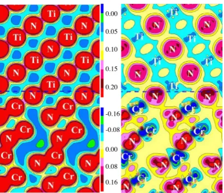
relations down to the atomic level, and theories that admit mul-tiple length scales, there has been rapid growth of activities in multiscale modelling. In order to make the computations tracta-ble, multiscale models generally make use of a coarse-fine decomposition. An atomistic simulation method, such as MD, is used in a small subregion of the domain in which it is crucial to capture the individual atomistic dynamics accurately. A con-tinuum simulation is used in all other regions of the domain in which the deformation is considered to be homogeneous and smooth. Since the continuum region is usually chosen to be much larger than the atomistic region, the overall domain of interest can be considerably large. The aforementioned QC methods, based on a combined MD-FE technique, can be applied to a multiscale modelling simulation, where MD is only used in localized regions in which the atomic-scale dynamics are important, and a continuum simulation (FE) used every-where else. For instance, Sun et al. [121, 122] have applied QC methods to simulate the nanometric cutting of crystal cop-per. Their study demonstrated that multi-scale simulation is fea-sible, not withstanding that there is still more work needed to be done to make multi-scale simulation more practical. The QC method is a directly coupled model between two scales (MD and FE). The unique characteristics of such a directly coupled method is that there is a hand shaking (HS) region to connect various scales wherein the message exchange, such as the velocity of particles (atoms or molecules), temperature, etc., is always a big challenge. At the same time, there is another way to utilize the advantages of various single scales, that is to say, the usage of one single scale could provide parameters/evidence for further investigation in another single scale. For instance, both FEM and MD simulation for nano-indentation showed that the calculated mechanical properties intrinsically depend on the interface contact conditions of the film/substrate [123]. Especially, investigations into the ‘‘template effect’’ from first-principles calculations have ascribed the super-hardness of multilayered coatings as the formation of coherent interfaces between the neighboring individual layers. Aiming at evaluat-ing the residual stress caused by lattice mismatch between neighboring layers, a approach based on the representative volume element (RVE), as shown in Figure 3, incorporating with first-principles calculations, is proposed from continuum mechanics principles [124]. At the atomic scale, the evidence for the good bonding between the multilayered coatings has been presented by first-principles calculation, as shown in
In the following, the constitutive relationship of each phase can be expressed as:
rm¼Lm: em ðfor them-phase TiNð ÞÞ; ð3Þ
ra¼La: ea¼La: ð emþeÞ ¼La: emþLa: e ðfor thea-phaseðCrNÞÞ; ð4Þ
whereDe*
is mismatch strain induced by the lattice mismatch between neighbouring layers. Based on the assumption that the in-plane strain and the out-of-plane stress components in both TiN and CrN phases should be identical to the corre-sponding values in the RVE to meet the compatibility and equilibrium conditions [125], the analytical solution of resid-ual stress can be obtained and the relationship between vari-ous parameters can also be described. The whole process presents another way to take advantage of modelling at vari-ous length-scales either in a top-down approach or in a bottom-up one.
6. Discussion
Multi-scale modelling can synthesizes atomistic and contin-uum methods to provide a more natural and coherent descrip-tion of material phenomenon than that obtained from the fragmented perspective for a limited individual scale. It has experienced some success with metals, but the usage for transi-tion nitride multilayered coatings has been lacking. Especially, there is essentially a request for research related to multiscale modelling to deal with defect/boundary/cracks. The challenges on the future development of numerical modelling for multilay-ered coatings may be from the following aspects:
1. Continuum models. Over the past few decades, contin-uum models have dominated materials modelling research. This approach of predicting material deforma-tions and failures by implicitly averaging atom-scale dynamics and defect evolutions over time and space, however, is valid only for large enough systems that include a substantial number of defects. As a result, numerous experimental observations of multilayered coatings cannot be readily explained within the contin-uum mechanics framework: dislocation patterns in fati-gue and creep, surface roughening and crack nucleation in fatigue, inherent inhomogeneity of plastic deformation, the statistical nature of brittle failure, plastic flow locali-zation in shear bands, and the effects of size, geometry and stress state on yield properties [126], etc. Moreover, the accuracy of the models needs to be validated for each case dealt with.
2. Molecular dynamics models. A MD model could only explore the phenomenon occurring at nanometric scale. Its applications to the analysis of multilayered coatings are limited by two factors: (a) Availability of the values of potentials for the atomic interactions to be examined. As well known, a key factor that determines the accuracy of a MD simulation significantly is the potential used to describe the interaction between atoms. A great effort has been made to develop various interatomic potentials fitted to different first principles, empirical and semi-empirical models, but only a few potentials for relatively simple material systems have been developed until now. Typically, multilayered coatings consist of at least two elements, and fewer potentials are available due to the increased complexity of interatomic action. On the other hand, simulations will often give acceptable results only if the potential was fitted for the problem under consider-ation, or one that is very similar. In other words, inter-faces of multilayers play an important role in their properties. Therefore, more attention should be paid to choice and development of potentials with proper descriptions of interfacial properties before these multi-layered systems could be simulated with MD accurately. (b) A typical MD simulation is still restricted to a very small system consisting of several million atoms or less and timescales in the order of picoseconds. A general acceleration methodology would have revolutionary implications that would relax current limitations on the use of MD.
3. First principles calculations.Many of the first principles calculations are confined to zero temperature, wherein the basic quantity is a Hamiltonian for the system expressed, in terms of the appropriate degrees of freedom. In princi-ple, Hamiltonian methods can be extended to equilibrium at finite temperatures by using the free energy. Inherently non-equilibrium situations are, however, fundamentally different and a general approach is not yet within grasp. At the same time, the limitation to the computational scale, i.e. the maximum number of atoms which can be included in a numerical model for first principles, is lim-ited. Generally, the maximum number of atoms used in a model does not exceed 100.
-0.08
0.16 0.00
0.08 -0.16 0.00
0.05
0.10
0.15
[image:11.595.52.280.71.267.2]0.20
The concept of multi-scale modelling embodies a compre-hensive description of a material, which requires understanding over both multiple time and length scales. Although the modelling for crystalline materials has coupled the nano- and intermediate-scale in a highly effective manner, the challenges remaining are the for longer time and length scales, largely due to the high requirement on computational effort associated with high-resolution calculations over such scales. In addition, multi-scale models also require that descriptions at all levels be consistent with each other. The requirement for consistency often demands the models for different process or pieces of a system to be coupled and solved concurrently. Consequently, multiscale modelling, on one hand, would still need more effec-tive coupling methods as an enabler. On the other hand, it does not satisfactorily address issues such as disparate time scales in the two regions, and it provides only a rather simplified treat-ment of the interfaces between the atomistic and continuum regimes.
For the aforementioned unique properties of multilayered coatings: the thickness of the individual layers of a coating would be at the nano-scale while the entire thickness of the coating is at the macro- or meso-scale. Single-scale methods such as first-principles calculations, Molecular Dynamics and the Finite Element Method will have difficulty in analyzing such multilayered coatings alone, due to the limitations to the time and length scales that each method is confined to. With further development of accurate inter-atomic potentials for the material-components in multilayered coatings and fur-ther development of time-integration algorithms used in the simulation, the MD and Multiscale modelling (MD coupled) will become a prominent tool for elucidating complex physical phenomenon. Although multi-scale modelling is important for the design and analysis of multilayered coatings, effort for the development of the modelling at individual length-scales could not be neglected, that is to say, efficiency and effectiveness of multiscale modelling not only concern how the models for indi-vidual length-scales are coupled/linked but also depend on how individual modelling methods and techniques for a particular length-scale could advance.
7. Conclusions and remarks
Multilayered coatings are currently a subject of intensive research because of their potential for a wide range of techno-logical applications and also due to their scientific importance. In this paper, development of the following numerical methods and models have been reviewed: (i) Continuum models; (ii) Molecular Dynamics simulations; and (iii) Nano-scale (first-principles calculations) modelling, for which examples of typical applications have been given.
In continuum models, FEM has been applied mainly for investigating the stress distribution, formation and propagation of crack under the (nano-) indentation or scratch test, formation of residual stresses, etc. Similarly, Molecular Dynamics (MD) simulations have also been applied mainly to the analysis of nano-indentations. Applications of first principles calculations are mainly presented on two kinds of mechanisms: ‘‘template
effect’’ and ‘‘super-hardness’’. Multiscale modelling, such as that with QC methods, has also been discussed.
In summary, multi-scale modelling is unambiguously a par-ticularly vibrant field of research related to engineering and sci-ences. Much of the excitement is being fuelled by increasingly sophisticated experiments that are capable of probing mater at the level of individual atoms or molecules. Interpretation of their experimental results require molecular and multiscale models to be connected with experimental observations. It is felt that more effort on the numerical modelling of multilayered coatings is needed. For example, when 400 nano-layers coated onto a substrate material needs to be modelled, there has to be a more effective method and more efficient way to achieve it. Developing accurate descriptions of inter-atomic potentials for multi-material elements, improving time-integration algorithms used in numerical simulations and developing more effective and efficient coupling methods for multiscale modelling are urgent tasks to be undertaken in order to develop a powerful numerical tool for high-efficiency performance prediction and process design for multi-layered coatings on engineering com-ponents, machining and forming tools.
Acknowledgements. The authors would like to acknowledge the European Commission for financial support to the research reported through the EU FP7 M3-2S project and acknowledge the permission for using the CASTEP code at the University of Strathclyde as a regi-stered academic license of CASTEP under the STFC/York/Accelrys agreement (UK). The authors would also like to thank all partners of the EU FP7 M3-2S project for their collaboration and encouragement for conducting this review work.
References
1. P. Hovsepian, D. Lewis, W. Mu¨nz, Surf. Coat. Technol. 133–134 (2000) 166.
2. Z. Zhou, W. Rainforth, Q. Luo, P. Hovsepian, J. Ojeda, M. Romero-Gonzalez, Acta Materialia 58 (2010) 2912. 3. C. Ma, J. Huang, H. Chen, Thin Solid Films 446 (2004) 184. 4. V. Flores, M. Rolda´n, C. Real, A. Pa´ez, G. Castro, J. Appl.
Phys. 104 (2008) 023519.
5. P. Yashar, W. Sproul, Vacuum 55 (1999) 179.
6. C. Mendibide, J. Fontaine, P. Steyer, C. Esnouf, Tribology Lett. 17 (2004) 779.
7. K. Holmberg, A. Mattewst, H. Ronkainen, Tribol. Int. 31 (1998) 107.
8. J. Chen, R. Ji, R. Khan, X. Li, B. Beake, H. Dong, Surf. Coat. Technol. 206 (2011) 522.
9. S. Yang, X. Li, K. Cooke, D. Teer, Appl. Surf. Sci. 258 (2012) 2062.
10. C. Ma, J. Huang, H. Chen, Surf. Coat. Technol. 133–134 (2000) 289.
11. Q. Sun, Z. Fu, Electrochim. Acta 54 (2008) 403.
12. U. Helmersson, S. Todorova, S. Barnett, J. Sundgren, L. Markert, J. Greene, J. Appl. Phys. 62 (1987) 481.
13. X. Chu, M. Wong, W. Sproul, S. Rohde, S. Barnett, J. Vac. Sci. Technol. A 10 (1992) 1604.
16. Z. Zhou, W. Rainforth, D. Lewis, S. Creasy, J. Forsyth, F. Clegg, A. Ehiasarian, P. Hovespian, W. Mu¨nz, Surf. Coat. Technol. 177–178 (2004) 198.
17. Q. Luo, Z. Zhou, W. Rainforth, P. Hovsepian, Tribology Lett. 24 (2006) 171.
18. Z. Zhou, C. Calvert, W. Rainforth, Q. Luo, L. Chen, P. Hovsepian, J. Phys.: Conf. Ser. 26 (2006) 95.
19. P. Hovsepian, Q. Luo, G. Robinson, M. Pittman, M. Howarth, D. Doerwald, R. Tietema, W. Sim, A. Deeming, T. Zeus, Surf. Coat. Technol. 201 (2006) 265.
20. Y. Chang, S. Yang, D. Wang, Thin Solid Films 515 (2007) 4722. 21. D. Lee, M. Kim, Y. Lee, S. Kwon, Surf. Coat. Technol. 141
(2001) 232.
22. D. Lee, M. Kim, S. Kwon, Met. Mater. Int. 7 (2001) 375. 23. Y. Otani, S. Hofmann, Thin Solid Films 287 (1996) 188. 24. S. Aouadi, K. Wong, K. Mitchell, F. Namavar, E. Tobin,
D. Mihut, S. Rohde, Appl. Surf. Sci. 229 (2004) 387. 25. V.M. Vishnyakov, V. Bachurin, K. Minnebaev, R. Valizadeh,
D. Teer, J. Colligon, V.V. Vishnyakov, V. Yurasova, Thin Solid Films 497 (2006) 189.
26. S. PalDey, S. Deevi, Mater. Sci. Eng. A 342 (2003) 58. 27. D. Lee, Surf. Coat. Technol. 173 (2003) 81.
28. C. Mendibide, P. Steyer, C. Esnouf, P. Goudeau, D. Thiaudie`re, M. Gailhanou, J. Fontaine, Surf. Coat. Technol. 200 (2005) 165. 29. C. Mendibide, P. Steyer, J. Fontaine, P. Goudeau, Surf. Coat.
Technol. 201 (2006) 4119.
30. C. Mendibide, P. Steyer, J. Millet, Surf. Coat. Technol. 200 (2005) 109.
31. M. Ramzan, A. Rana, M. Hafeez, E. Ahmed, A. Bhatti, M. Wasiq, M. Nadeem, Acta Chim. Slov. 61 (2014) 80. 32. X. Wang, H. Masumoto, Y. Someno, T. Hirai, Appl. Phys. Lett.
72 (1998) 3264.
33. D. Hinczewski, M. Hinczewski, F. Tepehan, G. Tepehan, Solar Energy Mater. Solar Cells 87 (2005) 181.
34. J. Selj, T. Mongstad, R. Søndena˚, E. Marstein, Solar Energy Mater. Solar Cells 95 (2011) 2576.
35. S. Chhajed, D. Poxson, X. Yan, J. Cho, E. Schubert, R. Welser, A. Sood, J. Kim, Appl. Phys. Expr. 4 (2011) 052503. 36. J. Zhang, Y. Xie, X. Cheng, H. Jiao, Z. Wang, Appl. Opt. 52
(2013) 5788.
37. J. Hiller, J. Mendelsohn, M. Rubner, Nat. Mater. 1 (2002) 59. 38. V. Medvedev, A. Boogaard, R. Meer, A. Yakshin, E. Louis,
V. Krivtsun, F. Bijkerk, Optics Express 21 (2013) 16964. 39. H. Raut, V. Ganesh, A. Nair, S. Ramakrishna, Energy Environ.
Sci. 4 (2011) 3779.
40. E. Louis, A. Yakshin, T. Tsarfati, F. Bijkerk, Prog. Surf. Sci. 86 (2011) 255.
41. G. Salazar-Alvarez, H. Lidbaum, A. Lo´pez-Ortega, M. Estrader, K. Leifer, J. Sort, S. Surin˜ach, M. Baro´, J. Nogue´s, J. Am. Chem. Soc. 133 (2011) 16738.
42. M. Yallapu, S. Othman, E. Curtis, B. Gupta, M. Jaggi, S. Chauhan, Biomaterials 32 (2011) 1890.
43. J. Li, H. Gao, Z. Chen, X. Wei, C. Yang, Anal. Chim. Acta 665 (2010) 98.
44. P. Pilla, V. Malachovska´, A. Borriello, A. Buosciolo, M. Giordano, L. Ambrosio, A. Cutolo, A. Cusno, Optics Express 19 (2011) 515.
45. S. Nair, G. Pookat, V. Saravanan, M. Anantharaman, J. Appl. Phys. 114 (2013) 064309.
46. J. Chen, G. Bell, B. Beake, H. Dong, Tribology Lett. 43 (2011) 351.
47. L. Fan, F. Zhou, C. Wang, H. Gao, S. Zhang, H. Zhang, X. Wang, IEEE Transactions on Ultrasonics, Ferroelectrincs, and Frequency Control 58 (2011) 451.
48. S. Zhang, D. Sun, Y. Fu, H. Du, Surf. Coat. Technol. 198 (2005) 74.
49. M. Nordin, M. Herranen, S. Hogmark, Thin Solid Films 348 (1999) 202.
50. M. Nodin, M. Larsson, S. Hogmark, Wear 232 (1999) 221. 51. M. Nodin, M. Larsson, S. Hogmark, Surf. Coat. Technol. 106
(1998) 234.
52. V. Teixeira, Thin Solid Films 392 (2001) 276.
53. P. Steyer, A. Mege, D. Pech, C. Mendibide, J. Fontaine, J. Pierson, C. Esnouf, P. Goudeau, Surf. Coat. Technol. 202 (2008) 2268.
54. M. Stueber, H. Holleck, H. Leiste, K. Seemann, S. Ulrich, C. Ziebert, J. Alloys Compd. 483 (2009) 321.
55. C. Lu, Y. Mai, Y. Shen, J. Mater. Sci. 41 (2006) 937. 56. S. Zhang, D. Sun, Y. Fu, H. Du, Surf. Coat. Technol. 198
(2005) 2.
57. K. Holmberg, H. Ronkainen, A. Laukkanen, K. Wallin, Surf. Coat. Technol. 202 (2007) 1034.
58. Z. Liu, C. Zhang, Y. Shen, Y. Mai, J. Appl. Phys. 95 (2004) 758. 59. J. Mackerle, Model. Simul. Mater. Sci. Eng. 13 (2005) 935. 60. B. Bhushan, W. Peng, Appl. Mech. Rev. 55 (2002) 435. 61. J. Luo, Y. Liu, E. Berger, Computational Mechanics 24
(2000) 448.
62. H. Djabella, R. Arnell, Thin Solid Films 213 (1992) 205. 63. L. Stephens, Y. Liu, E. Meletis, J. Tribol. 122 (2000) 381. 64. K. Bouzakis, N. Michailidis, G. Erkens, Surf. Coat. Technol.
142–144 (2001) 102.
65. X. Tan, Y. Shen, Compos. Sci. Technol. 65 (2005) 1639. 66. X. Zhao, Z. Xie, P. Munroe, Mater. Sci. Eng. A 528
(2011) 1111.
67. H. Pelletier, J. Krier, A. Cornet, P. Mille, Thin Solid Films 379 (2000) 147.
68. T. Aoki, H. Hatta, T. Hitomi, H. Fukuda, I. Shiota, Carbon 9 (2001) 1477.
69. J. Chen, S. Bull, Thin Solid Films 517 (2009) 3704.
70. K. Holmberg, A. Laukkanen, H. Ronkainen, K. Wallin, Tribol. Int. 38 (2005) 1035.
71. T. O¨ zel, T. Thepsonthi, D. Ulutan, B. Kaftanoglu, CIRP Ann. – Manuf. Technol. 60 (2011) 85.
72. T. O¨ zel, M. Sima, A.K. Srivastava, B. Kaftanoglu, CIRP Ann. – Manuf. Technol. 59 (2010) 77.
73. W. Grzesik, M. Bartoszuk, P. Nieslony, J. Mater. Process. Technol. 164–165 (2005) 1204.
74. R. Coelho, E. Ng, M. Elbestawi, Int. J. Mach. Tools Manuf. 47 (2007) 263.
75. K. Holmberg, H. Ronkainen, A. Laukkanen, K. Wallin, S. Hogmark, S. Jacobson, U. Wiklund, R. Souza, P. Sta˚hle, Wear 267 (2009) 2142.
76. H. Ng, Z. Gan, Finite Elem. Anal. Des. 41 (2005) 1235. 77. O. Sarikaya, E. Celik, Mater. Design 23 (2002) 645. 78. V. Teixeria, Vacuum 64 (2002) 393.
81. H. Liu, J. Tao, Y. Gautreau, P.Z. Zhang, J. Xu, Mater. Design 30 (2009) 2785.
82. O. Sayman, F. Sen, E. Celik, Y. Arman, Mater. Design 30 (2009) 770.
83. M. Toparli, F. Sen, O. Culha, E. Celik, J. Mater. Process. Technol. 190 (2007) 26.
84. M. Far, J. Absi, G. Mariaux, F. Dubois, Mater. Design 31 (2010) 772.
85. X. Pan, L. Yan, J. Xu, Thin Solid Films 354 (1999) 154. 86. E. Bemporad, M. Sebastiani, F. Casadei, F. Carassiti, Surf. Coat.
Technol. 201 (2007) 7652.
87. R. Lakkaraju, F. Bobaru, S. Rohde, J. Vac. Sci. Technol. A 24 (2006) 146.
88. T. Gorishnyy, L. Olson, M. Oden, S. Aouadi, S. Rohde, J. Vac. Sci. Technol. A 21 (2003) 332.
89. J. Feng, Y. Qin, Q. Zeng, E. Almandoz, G. Fuente, H. Dong, R. Koodakal, J. Michler, J. Multiscale Modelling 03 (2011) 1. 90. X. Xu, A. Needleman, Model. Simul. Mater. Sci. Eng. 1
(1993) 111.
91. X. Xu, A. Needleman, J. Mech. Phys. Solids 42 (1994) 1397. 92. P. Geubelle, J. Baylor, Composites: Part B 29B (1998) 589. 93. N. Chandra, H. Li, C. Shet, H. Ghonem, Int. J. Solids Struct. 39
(2002) 2827.
94. S. Nekkanty, M. Walter, R. Shivpuri, J. Mechanics Mater. Struct. 2 (2007) 1231.
95. M. Payne, M. Teter, D. Allan, T. Arias, J. Joannopoulos, Rev. Mod. Phys. 64 (1992) 1045.
96. J. Leopold, K. Heller, A. Meyer, R. Wohlgemuth, J. Multiscale Modelling 3 (2011) 91.
97. Y. Chen, W. Zhuang, S. Wang, J. Lin, D. Balint, D. Shan, Chinese J. Mech. Eng. 25 (2012) 860.
98. M. Perucca, S. Durante, U. Semmler, C. Ru¨ger, G. Fuentes, E. Almandoz, IOP Conf. Series, Mater. Sci. Eng. 40 (2012) 012004.
99. M. Karimpour, D. Balint, K. Rzepiejewska-Malyska, A. Szerling, J. Michler, J. Lin, Comput. Mater. Sci. 68 (2013) 384.
100. J. Haile, Molecular dynamics simulation elementary methods, 1st edn., John Wiley & Sons, Inc., New York, NY, USA, 1992. 101. M. Allen, D. Tildesley, Computer simulation of liquids,
1st edn., Oxford University Press, New York, 1987
102. D. Rapaport. The art of Molecular Dynamics Simulation, in: Dennis Rapaport (Ed.), 2nd edn., Cambridge University Press, New York, 2004
103. D. Saraev, R. Miller, Acta Mater. 54 (2006) 33.
104. Y. Cao, J. Zhang, Y. Liang, F. Yu, T. Sun, Appl. Surf. Sci. 257 (2010) 847.
105. T. Fang, J. Wu, Comput. Mater. Sci. 43 (2008) 785.
106. L. Yuan, Z. Xu, D. Shan, B. Guo, Appl. Surf. Sci. 258 (2012) 6111.
107. L. Yuan, Z. Xu, D. Shan, B. Guo, Appl. Surf. Sci. 282 (2013) 450.
108. Z. Xu, L. Yuan, D. Shan, B. Guo, H. Dong, X. Li, J. Multiscale Modelling 3 (2011) 23.
109. D. Yin, X. Peng, Y. Qin, Z. Wang, J. Appl. Phys. 108 (2010) 033714.
110. X. Li, W. Wu, H. Dong, Surf. Coat. Technol. 205 (2011) 3251.
111. Z. Wang, S. Tsukimoto, M. Saito, Y. Ikuhara, Phys. Rev. B 79 (2009) 045318.
112. M. Finnis, J. Phys.: Condens. Matter 8 (1996) 5811. 113. L. Liu, S. Wang, H. Ye, Surf. Inter. Anal. 35 (2003) 835. 114. V. Chawla, D. Holec, P. Mayrhofer, J. Phys. D: Appl. Phys. 46
(2013) 045305.
115. R. Zhang, S. Veprek, Mater. Sci. Eng. A 448 (2007) 111. 116. R. Zhang, S. Veprek, Acta Mater. 55 (2007) 4615. 117. S. Sheng, R. Zhang, S. Veprek, Acta Mater. 56 (2008) 968. 118. D. Holec, R. Rachbauer, L. Chen, L. Wang, D. Luef,
P. Mayrhofer, Surf. Coat. Technol. 206 (2011) 1698. 119. C. Stampfl, A. Freeman, Appl. Surf. Sci. 258 (2012) 5638. 120. R. Zhang, S. Sheng, S. Veprek, Appl. Phys. Lett. 91
(2007) 031906.
121. X. Sun, S. Chen, K. Cheng, D. Huo, W. Chu, J. Eng. Manuf. 220 (2006) 1217.
122. X. Sun, K. Cheng, Int. J. Adv. Manuf. Technol. 47 (2010) 891. 123. X. Huanag, A. Pelegri, Compos. Sci. Technol. 67 (2007) 1311. 124. D. Yin, X. Peng, Y. Qin, Z. Wang, J. Multiscale Modelling 3
(2001) 65.
125. X. Peng, J. Fan, J. Zeng, Int. J. Solids Struct. 39 (2002) 435. 126. W. Liu, E. Karpov, S. Zhang, H. Park, Comput. Methods Appl.
Mech. Eng. 193 (2004) 1529.
![Figure 1. Transmission electron microscopy (TEM) image of (a) TiN/CrN [28–30]; and (b) TiAlN/VN [2] multilayered coatings.](https://thumb-us.123doks.com/thumbv2/123dok_us/1653878.118932/2.595.124.463.75.224/figure-transmission-electron-microscopy-image-tialn-multilayered-coatings.webp)