Virtual Integration Platform for Computational Fluid Dynamics
W Wang, A Duffy, I Whitfield and K Mohamed,University of Strathclyde, UK S Gatchell,The Hamburg Ship Model Basin (HSVA), GermanyH Prins,Maritime Research Institute Netherlands (MARIN), Netherlands
SUMMARY
Computational Fluid Dynamics (CFD) tools used in shipbuilding industry involve multiple disciplines, such as resistance, manoeuvring, and cavitation. Traditionally, the analysis was performed separately and sequentially in each discipline, which often resulted in conflict and inconsistency of hydrodynamic prediction. In an effort to solve such problems for future CFD computations, a Virtual Integration Platform (VIP) has been developed in the University of Strathclyde within two EU FP6 projects – VIRTUE and SAFEDOR1. The VIP provides a holistic collaborative environment for designers with features such as Project/Process Management, Distributed Tools Integration, Global Optimisation, Version Management, and Knowledge Management. These features enhance collaboration among customers, ship design companies, shipyards, and consultancies not least because they bring together the best expertise and resources around the world. The platform has been tested in seven European ship design companies including consultancies. Its main functionalities along with advances are presented in this paper with two industrial applications.
1. INTRODUCTION
A variety of tools are used throughout a ship’s lifecycle to facilitate different aspects of ship design for example; Computer Aided Design (CAD), Computational Fluid Dynamics (CFD), optimisation, and visualisation. CFD tools are used in both civil and military shipbuilding industry during various stages of ship design involve multiple disciplines, such as resistance, propulsion, manoeuvring, sea keeping, and cavitation. Traditionally, the CFD analysis was performed separately and sequentially in each discipline [1]. Specifically, it starts with a ship surface description extracted from a CAD system. Based on the surface, a computational grid is generated for resistance calculations. Meanwhile, several variants are defined by hand for minimising resistance, each based upon the previous variants. The best option is then selected for a viscous flow optimisation of the aft body. The optimisation is generally based on the knowledge of naval architect. Subsequent studies include the propeller, hull-pressure fluctuations, cavitation, and performance in calm water. The wake field of the hull is static input to this optimisation. Additional sea-keeping calculations may lead to a further adjustment of the hull or appendages. Finally, manoeuvring characteristics are determined and if deemed sufficient, the design analysis is finished. Results are presented to the customer on paper or through off-line animations.
It can be seen from such practice that the tools used for different aspects of CFD analysis and even different levels of detail within each aspect were often poorly integrated and mutual influences and interactions between these aspects were not fully considered. This, in turn, often resulted in conflict and inconsistency of hydrodynamic prediction [1]. With more and more global collaborations between companies, such problems become more severe. In an effort to solve such problems
for future CFD computations, a Virtual Integration Platform (VIP) has been developed in the University of Strathclyde within two EU funded projects – VIRTUE and SAFEDOR1, under the FP6 framework [2, 3].
The platform is a holistic collaborative design environment and provides a number of features that enable users to define and enact collaborative processes, integrate distributed tools within a process, manage versions of design history, carry out global optimisation, and reuse design knowledge. This enhances collaboration among customers, ship design companies, shipyards, and consultancies not least because they bring the best expertise and resources around the world together. The platform has been tested in seven European ship design companies throughout its development [4]. The case studies undertaken to date have revealed significant potential for its future application in shipbuilding industry. For instance, it has enabled MARIN (Maritime Research Institute Netherlands) in Netherlands to reduce the working time for one process by 67%. In the case of HSVA (The Hamburg Ship Model Basin) in Germany, the platform has enabled some processes that were initially could only be performed by a specific expertise to be enacted by non-specialist users through knowledge management.
The technology aspect for development of the VIP has been presented in a previous paper [2]. This paper focuses on its functionalities, advances and its applications. The platform architecture is illustrated in Section 2. Its main functionalities and advances are
1
presented in Section 3. Two industrial applications are shown in Section 4. The limitations and advantages of the platform as well as its future applications are discussed in Section 5, and Section 6 gives the concluding remarks to the paper.
2. VIP ARCHITECTURE
A number of systems supporting collaborative design have been developed, driven by the development of web technologies and theories or technologies of artificial intelligence (e.g. agent theory), such as those in [5, 6]. Web technologies, such as Java, search engines, XML (eXtensible Markup Language), and RMI (Remote Method Invocation), enable distributed designers to access catalogue, design on components and sub-assemblies, design tools, and services, and to communicate with other members. Such technologies enable the VIP to provide a collaborative environment for designers through the provision of data and task level management, and co-ordination, to enable CFD and design tools to be brought together and operate in a unified and holistic manner.
The VIP has been developed based on the Scrum methodology [7]. Specifically, user requirements of the platform were collected, numbered, and prioritised by the VIP end users. Those with higher priority were addressed within the work plan. Meanwhile, the priority, progress, and evolution of existing requirements were discussed and new requirements were introduced. Upon introducing new requirements, all those that have not been addressed were re-prioritised, which results in rolling work plan throughout the development of the platform. This methodology enhanced interaction between the developer and end users, and ensured the VIP met the end users’ requirements. It has been proved successful in the VIRTUE project [8].
The developed VIP can be deployed by distributed designers/users to work collaboratively over a network. A native XML database (Common model) is employed as a centralised database storing parameter data and meta-data relating to the URLs of all file data, which is subsequently stored on distributed FTP servers deployed flexibly [3].
3. VIP FUNCTIONALITIES
The VIP is a holistic collaborative platform, providing designers with functionalities that enable them to define and enact collaborative design processes, integrate distributed tools within a process, manage versions of design history, carry out global optimisation, visualise multiple 4D design results, and reuse design knowledge.
The VIP was developed using Java. As such, it is compatible with a variety of Operation Systems (OS), such as Microsoft Windows, Linux, Mac, and UNIX. In addition, the VIP delivers flexible protocol and communication mechanisms that enable it to communicate across software developed with different programming languages.
To support collaborative design, the VIP provides multiple user type management, which include project manager and specialist user. While the former is permitted to create projects, allocate users and tools, and monitor project progress, the latter is entitled to carry out activities such as configure and enact tasks, and monitor project progress. In addition, the VIP features the following functionalities, which reveal its advances over other integration platforms.
3.1 COLLABORATIVE ENVIRONMENT
Globalisation requires distributed designers to work within the same project process to collaborate or co-operate towards a common goal. The VIP promotes collaborative support to design teams regardless of geographical location, both within and between organisations.
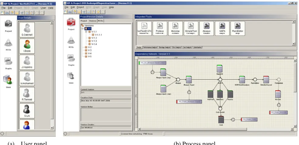
The network architecture of the VIP facilitates users with better collaboration through its built-in communication mechanism. It consolidates expertise across organisations to share design tasks, tools, data, and knowledge. Specifically, designers can read project related news once they log into the VIP. They will access consistent common data, and visualise common design processes located in the central database. As such, they automatically receive updates for the project they are working on. Moreover, users can view other VIP users, and be informed whether they are working the same project, and are online or offline as seen in Figure 1 (a). In addition, the collaboration is also facilitated by the following functionalities.
3.2 PROJECT/PROCESS MANAGEMENT
[image:3.612.64.557.75.315.2]
(a) User panel (b) Process panel
Figure 1: VIP user interface
3.3 DISTRIBUTED TOOLS INTEGRATION
Distributed disparate tools can be easily integrated into the VIP. The tools can be interactive or automated commercial or in-house codes, they can also be scripts and macros. The generic wrappers form the basis for integrating tools within the VIP, which supports the definition of data manipulation actions (e.g. uploading, downloading, deletion, adding, and updating, etc) and data conversion, and the launch of these tools through the platform (i.e. through running the executables). The wrapping is “loosely coupled”, that removes any limitations regarding the range of tools that are integrated, and also provides extended functionality to the process, such as visualisation and optimisation. By integrating distributed tools, the VIP promotes collaboration by bringing together both distributed activities and expertise within a virtual platform. Through the user interface, each user can visualise all the tools that they have integrated, and recognise the tools for the current working project - Figure 1 (b).
3.4 PROCESS VISUALISATION
The VIP user interface provides real-time visualisation of projects and processes - Figure 1 (b). It displays different types of nodes that represent all the tools, file and parameter items, transformations, and dependencies within a process. Moreover, it illustrates the status of the process through different colours of the nodes. The status of the process is automatically updated for all users of the VIP who are working with the same process, resulting with a common visualisation of process state.
3.5 CONSISTENCY MANAGEMENT
Keeping a consistent data set and visualising the consistency status to users is crucial since the use of the tools and data within the VIP could be undertaken on an ad-hoc basis by designers working on the same project, but within different departments, organisations, or locations. The consistency management in the VIP blocks two users from editing the same data item in the database simultaneously. In doing so, it locks all the data items that have dependency links with an activity (either executing a tool or initiating a transform). The VIP will unlock the items upon completing the activity. As the consistency status of all the data is maintained in one centralised database, all distributed users subsequently have the same consistent information following any change of the process, and also up-to-date visual representation of such status. All the consistent items are shown to users in green, and the inconsistent items are in red - Figure 1 (b). Such status also shows users the activities that have been undertaken, as well as those are left to be completed.
3.6 VERSION MANAGEMENT
traceability through backtracking related versions of data and results.
Moreover, parameters from multiple design versions can be compared through the creation of various graphs. These versions represent themselves as points or lines on different types of graphs such as Category, Spider, X-Y, or Dependency. Figure 2 illustrates an X-Y graph with different versions represented by different coloured lines. This gives designers an intuitive comparison between different versions.
[image:4.612.63.296.197.371.2]
Figure 2: X-Y graph of design versions
3.7 ENABLE MULTIPLE RESULTS
VISUALISATION
Visualisation is important for any kind of CFD analysis. In ship development - depending on the particular application - different data entities are encountered, requiring various visualisation techniques. For resistance prediction or sea-keeping computations mainly 2D surface meshes are deployed. In addition to such meshes, quantities like pressure values or boundary streamlines are usually displayed by means of colour coding or contouring. Scalar data, like pressure or vorticity, can be visualised in 3D using iso-surfaces or direct volume rendering. Flow structure is commonly analysed using streamlines or via particle tracing. By integrating visualisation tools, such as AMIRA, the VIP enables designers to visualise different types of data, and compare multiple design results from 2D to 4D simultaneously.
3.8 GLOBAL OPTIMISATION
Ship design typically involves a number of disciplines, for example resistance, propulsion, manoeuvring, sea keeping, and cavitation, each contributing in various stages to its detailed definition. Traditionally, the analysis in each discipline is performed separately with a sequential approach. The single disciplines can however interact, and very often trade-offs exists between multiple disciplines, Improvements in one discipline may result with deterioration in others. Therefore, the optimal
[image:4.612.342.558.268.372.2]solution must be searched in the framework of the Multidisciplinary Design Optimisation (MDO) [9], or global optimisation, where different aspects of a design problem are considered concurrently as shown in Figure 3. The VIP provides multiple objectives and criteria global optimisation, which can be performed for a process including multiple work flows of different aspects of ship design. The optimisation can be performed either through the optimisation function built in the VIP, such as GA (Generic Algorithm), or an external optimiser, such as modeFrontier, that provides a comprehensive set of advanced solutions to the general problem of design exploration and optimisation. By optimising the process, designers can consolidate conflicts between disciplines while reaching an optimal solution, with multiple objectives and criteria.
Figure 3: Global optimisation
3.9 DECENTRALISED DATA MANAGEMENT The VIP uses a decentralised data approach. With such an approach, the physical data are stored decentralised in local machines while the indices of the data are stored in a central database. Such an approach provides several advantages for users:
• Data consistency: As all the meta data are stored in one single Database Server, which includes all data relating to user accounts, projects, version management, dependency network consistency status, graphs, and indexes of all the file items, users access a consistent set of data no matter where they access the platform. Any type of change that a designer makes within a project is automatically updated within the database. Other designers automatically receive updates for the project they are working on via updates with the database
• Reduced database size: For all the file items related to projects, the database only stores the indexing (meta data), rather than the data itself, which resulted a minimized database size.
• Reduced network traffic volume: As the file data are stored decentralised in local computers, transferring over network is based on requirements, which resulted a minimised network traffic volume. 3.10 KNOWLEDGE MANAGEMENT
Sea keeping
Manoeuvring
Resistance
Effective combination of different tools in a complex design process depends upon different kinds of procedural knowledge [10]: how to prepare and format input data; how to configure and run tools; how to properly interpret the output; how to combine and transform output from one or more tools to input for another; how to organise and plan the workflow; how to record and document the task execution and results. These are knowledge acquired with experience. But having to apply these different kinds of knowledge in the same design situation can and does distract designers from the main concerns of the design task. Moreover, unless a company has a proper knowledge management approach, such knowledge can be easily lost if the designers leave the company. The VIP can manage such procedural knowledge through capturing them in design process templates as configuration knowledge, which can be reused in other processes by same or different designers.
In addition to the management of procedural knowledge, the version management mentioned in Section 3.6 also provides knowledge management mechanism of multiple design solutions, which is declarative knowledge [10].
4. VIP INDUSTRIAL APPLICATIONS
Throughout its development, the VIP has been tested in seven companies through ten design applications within VIRTUE [4], including one was developed for a commercial project. The case studies showed a number of advances of the platform, such as time efficiency, cost reduction, knowledge capturing, and facilitating testing code development. Due to length limitation, this section only presents two VIP applications in HSVA and MARIN. The first one is presented with detailed description, while the second one is presented only with its main results.
4.1 PROPELLOR DESIGN 4.1 (a) Background
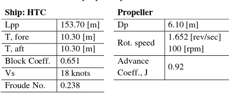
[image:5.612.331.564.81.177.2]The propeller design carried out in HSVA is a propulsion prediction exercise to compute and adapt the propeller thrust and torque for a given operational condition. The container ship, Hamburg Test Case (HTC) [11], was selected for numerical analysis, which has been widely published and was selected as one of the standard test subjects for VIRTUE. The propeller blade sections were based on a generic NACA 66 profile (meanline A=0.8). The propeller data were fixed except for the mean value of the blade pitch. The main parameters of the vessel and propeller are given in Table 1:
Table 1: Vessel and propeller parameters
Ship: HTC Propeller
Lpp 153.70 [m] Dp 6.10 [m] T, fore 10.30 [m]
T, aft 10.30 [m] Rot. speed
1.652 [rev/sec] 100 [rpm] Block Coeff. 0.651
Vs 18 knots
Advance
Coeff., J 0.92 Froude No. 0.238
[image:5.612.333.564.524.665.2]Propulsion prediction evaluations are necessary to ensure that the propeller performance matches the predicted engine power or the required thrust at the right RPM. The non-uniform flow of the wake distribution affects the propeller performance. One way to address this is to adjust the propeller geometry, taking this non-uniform flow into account. This case study applied parametric principles to propeller design. The potential of this approach was investigated in the VIP.
Figure 4 illustrates the general workflow of a propeller design exercise. The initial flow condition, “flow condition 1”, contains the relevant data for the operating conditions, given by “RANSE wake” and “RESISTANCE prediction”. The “RESISTANCE prediction” (including thrust deduction) is the target thrust value that the propeller should produce (within reasonable margin). In this example, only one set of flow conditions is considered; the changes are made to the geometry. A baseline geometry, “geometry 1”, is established, and its performance, “performance point 1”, is produced from “computation”. This performance point is then compared with the target thrust value. Any modifications to the geometry are defined in the subsequent “geometry 2”, and the associated “performance point 2” to be compared to the target value. Many parameters can be considered when modifying a propeller design: pitch, camber, thickness, rake, skew, etc. This process repeats until all performance criteria have been fulfilled.
geometry 1
computation
flow condition 1 geometry 2
performance point 1 performance
point 2 RANSE
wake
RESISTANCE prediction
geometry 1
computation
flow condition 1 geometry 2
performance point 1 performance
point 2 RANSE
wake RANSE
wake
RESISTANCE prediction RESISTANCE
prediction
4.1 (b) Process in VIP
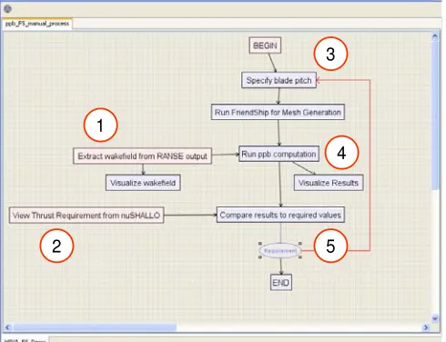
Figure 5 shows the propeller design process within the VIP2. Each box in the process represents a task to be performed by a user and has been allocated with one or more tools. The user has the option which tool to use, depending on availability and preference. The process for this case study consists of five main tasks:
1
3
4
2 5
1
3
4
2 5
Figure 5: Propeller design process within the VIP
̇ Task 1 Extract wake distribution from RANSE output
A double-body RANSE computation was performed to produce the wake distribution as input to the ppb computation. This computation was performed outside the VIP since the tool had not been integrated. However, a data translation module was executed from within the VIP and extracted the wake distribution information from the RANSE output, which was saved to the set of “derived data” in the common data model and used by the ppb code. Though the additional sub-task, “visualize wakefield” is not essential, it provides a useful graphical representation of the wake distribution.
̇ Task 2 Compute thrust requirements in nuShallo The panel code nuShallo is an in-house, commercially available code developed by HSVA, which was fully integrated and executed within the VIP. A panel mesh and a text control file wer used as input. In this study, a single value for the total resistance was parsed from the nuShallo output text file. This value was stored in the platform common data model and could be recalled at any time.
2
The VIP user interface has been involved to a more intuitive one, though providing similar functionalities. The propeller design was conducted in the VIP with the original user interface.
̇ Task 3 Create geometry and mesh in Framework
An open and flexible set of parameters was specified using FRIENDSHIP-Framework. To simplify the case study, the design changes were limited to one parameter: pitch distribution. A baseline propeller was modelled so that the pitch distribution curve could be shifted by a single control value. The FRIENDSHIP-Framework generated a panel mesh, which was then evaluated using HSVA’s propeller panel-based (ppb) code. It was configured to run in batch mode in the VIP, where the VIP passed the mean pitch value to the FRIENDSHIP-Framework on execution. The FRIENDSHIP-FRIENDSHIP-Framework then used this value to generate a new propeller geometry and the corresponding panel mesh, fully automated. This batch mode execution is necessary for later implementation of formal optimisation methods. The user still has the option of running the Framework in interactive, GUI mode, and would have full control over the entire geometry model.
̇ Task 4 Compute performance in ppb
HSVA’s in-house propeller panel code, ppb, was used as the third main component. A panel mesh file, wake distribution file, and some text configuration files were used as input to the computation. As output, ppb created a text file listing the numerical results, along with several PostScript files and a Tecplot file for visualisation. The pressure distribution over the blade is shown in the Amira visualisation below:
[image:6.612.332.568.422.620.2]
Figure 6: Pressure on blade pressure side
For the case study, only the thrust value was needed, which was extracted from the text results, and uploaded to the common data model as “derived data”. The data management system in the VIP tracks each iteration of the design process, for evaluation in Task 5.
By automating the data management and the workflow, the execution time for the entire workflow was reduced significantly. Based on the experience with the above case study, it iss estimated that with the introduction of formal optimisation methods, the time savings for this type of process could be even greater. Allowing the process to run, autonomously, overnight could evaluate hundreds of design variations over a multiple parameter search field. Additionally, less time was required from the “expert user”, especially for the in-between steps, where little decision-making was required. For the simple one-parameter optimisation demonstrated in this case study, the expert was only needed at the beginning for set-up, and at the end to verify that the requirements had been met.
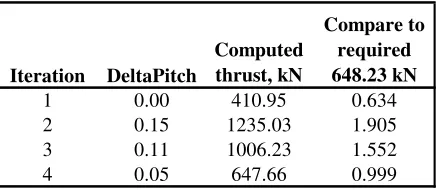
[image:7.612.65.283.197.292.2]The generic wrapper in the VIP was configured to create a text file automatically, with the input and output values and the requirements, where necessary. The thrust value from ppb in task 4 was then compared to the nuShallo thrust prediction, from task 2. The design was considered successful when these two values were within 10% (sea margin). If not, another iteration, tasks 3-5, was necessary. The table below shows the results of four (4) iterations to satisfy the convergence criterion:
Table 2: Propeller design evaluation
Iteration DeltaPitch
Computed thrust, kN
Compare to required 648.23 kN
1 0.00 410.95 0.634
2 0.15 1235.03 1.905
3 0.11 1006.23 1.552
4 0.05 647.66 0.999
Although this is a simplistic example, the usefulness of this task should not be underestimated. Complex scripts, macros, or formatting tags may be included in the tool configuration, a step towards automatic report generation (realised in the next case study). All the improvements and advances brought by the VIP are cost effective for company, which is important in current competitive ship design industry.
4.1 (c) Lessons learned
Through the case study, several areas of improvement were identified in individual tools, as well as the overall workflow.
Tool improvements 4.2 MULTI-OBJECTIVE OPTIMISATION
The VIP has facilitated the in-house codes improvement as a direct result of integrating the tool into the platform, which shows that the VIP can also be used for testing CFD/design tools being developed. In this case study, the tools were expanded to include more options for input and output formats, in some cases for more adherence to a common data format. Command-line arguments were included in the executable, thereby eliminating the need for the user to manually input certain values.
4.2 (a) Background
The multi-objective optimisation case study carried out in MARIN involved three disciplines of ship hull design: resistance, manoeuvring, and sea keeping. This is a typical project scope in MARIN, building a basis for optimisation scenario. In addition, in the context of VIRTUE, the case study combines research results from three other work packages, hence represents a comprehensive case study.
Simplified process
The objectives of the hull form optimisation are three folds: to minimise resistance of a ship in sea; to optimise turning circle diameter in waves to improve ship manoeuvrability; meanwhile, to restrict pitch motion to optimise ship behaviour in sea keeping.
The workflow for this exercise was also simplified (from the designer’s point of view) in that all of the configuration files for a ppb computation were included in the tool wrapper. These files could be left unchanged, and the user was not overwhelmed by the many details they included. Consequently, this reduced the amount of direct, manual interaction with the configuration files, resulted in time saving.
As each criterion is normally analysed by a different designer at MARIN, who are located in different floors in the company, the analysis was carried out over three computers connected by a LAN, each performing one aspect of ship design. In this study, the main solvers used are RAPID for resistance, PRECAL for sea keeping, and SURSIM for manoeuvring calculation. To carry out the optimisation, the activities within the case study include: Knowledge capturing
By saving and reusing configuration files, the “know how” knowledge of expertise was captured and can be learned, reused by non-specialist users. In this example, the VIP enables error free enactment for non-specialist users to enact a process that previously could only be done by specialists.
• Configure the VIP for optimisation • Set up the optimisation in VIP • Set up the optimisation in optimiser
• Run a Design of Experiments
Time Savings •
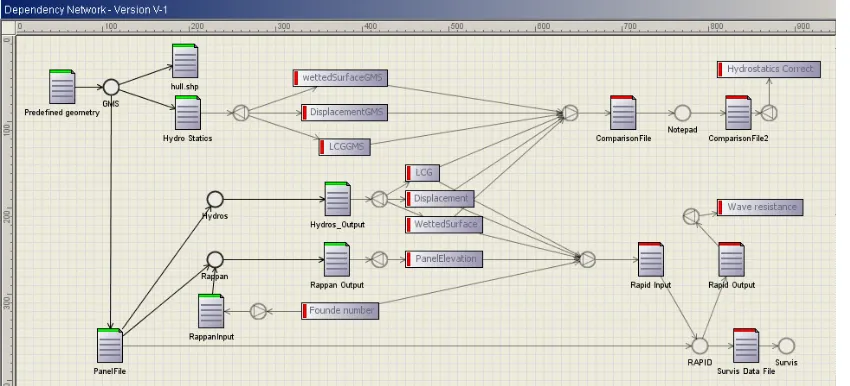
Figure 7: Multi-objective optimisation process (Resistance workflow)
[image:8.612.167.521.299.480.2](a) Bulb width variation (b) Bulb length variation Figure 8: Multi-objective optimisation results
4.2 (b) Process in VIP
The multi-objective optimisation process includes three parallel workflows, which consolidate the tools, input and output files, parameters, as well as the transforms between parameters and files. In the process, RAPID was integrated in the resistance workflow, SURIM was integrated in the manoeuvring workflow, and PRECAL was integrated in the sea keeping workflow. Due to space limitation, only the resistance workflow is shown in Figure 7. Of each tool, the input data such as geometry and speed were downloaded to the local computer before its execution, and calculation results were uploaded to the server following the tool execution. For file items, only indexing of the files were downloaded and uploaded. All the activities in the process were configured to run automatically. The process ended with a result storing node, which can store automatically the
results of both calculation and graphics, as well as produce report for the analysis.
To set up optimisation in the VIP, through the optimisation wizard, the designers select the parameters to be optimised, the optimisation criteria (in this case is the minimised resistance, turning circle diameter, and pitch motion), and the optimiser.
analysed through visualisation and comparison of the results (with integration of visualisation tool in the proess). Figure 8 shows the optimisation results with Bulb width variation, in (a), and Bulb length variation in (b).
4.2 (c) Lessons learned
Through running the multi-objective optimisation project within the VIP, it was revealed that it brought the following advances to the designers:
Time efficiency in this case study is obvious. Automation of the workflow and data flow resulted in the run time of the process been deduced from six to two days, which is 67% time reduction.
The VIP guaranteed data consistency across resistance, manoeuvring, and sea keeping calculation of the hull. Moreover, by storing the correct configuration of the tools used in this project in the platform, errors caused by human carelessness were eliminated.
The VIP users found it especially useful to automatically produce analysis report following each analysis. It saved time for the designers by avoiding composing such report, hence enabling them to focus more design related tasks.
The VIP used in this case study is intuitive for designers to build up projects and processes, integrate tools, and configure inputs and outputs for the tool. For this case study, it took only three hours for a first-time user to be familiar with the platform, build up the process and finish configuration. Overall, designers in MARIN were positive about the applicability of the VIP in the future CFD computations.
5. DISCUSSIONS
The VIP has been developed within two European research projects. Though it’s not a commercial platform yet, a number of advances have been revealed, which made it a unique platform for CFD computations and most other design activity. The test cases showed that it had the ability to enhance collaboration among customers, ship design companies, shipyards and consultancies. This was realised through the functionalities and advances presented in the previous two sections. However, through the case studies, additional functionalities were identified to enhance the platform. Among them, the following two were recognised as prominent for it to become a competitive platform.
Currently the processes are still constructed in one level. It could benefit users to have hierarchical structure of process, so that sub-process could be modulised in a parent process. This would not only help the designer have a clearer view of a complex process, but also
facilitate knowledge reuse, as the modulised process can be reused across different projects and organisations. Though versions of design history can be saved and navigated in the VIP, data mining has not been provided by the VIP. However, it would enhance design efficiency for the VIP to have the data mining function, so that results related with particular versions of parameters can be searched and explored across organisation(s).
6. CONCLUSION
Computational Fluid Dynamics (CFD) tools used in shipbuilding industry involve multiple disciplines. Traditionally, the analysis was performed separately and sequentially in each discipline with low integration, which often resulted in conflict and inconsistency of hydrodynamic prediction. This paper presented a Virtual Integration Platform (VIP) developed in the University of Strathclyde within two EU funded projects – VIRTUE and SAFEDOR, under the FP6 framework. The VIP provides a holistic collaborative environment for designers with features such as Project/Process Management, Distributed Tools Integration, Process visualisation, Consistency Management, Version Management, Enable Multiple results Visualisation, Global Optimisation, Decentralised Data Management, and Knowledge Management. These features enhance collaboration among customers, ship design companies, shipyards and consultancies. Moreover, its advances in time efficiency, facilitate testing developing CFD tools, error free enactment, and cost efficiency have been revealed through ten case studies across seven ship design companies and consultancies. Though there are still plans for the further development of the VIP, it has been demonstrated as a unique platform for future CFD computations.
7. ACKNOWLEDGEMENTS
This research is funded by the SAFEDOR and VIRTUE projects, which were partially funded by the European Commission (contract numbers 516278 and FP6-516201 respectively), within the Sixth Framework Programme. The opinions expressed are those of the authors and should not be construed to represent the views of either the SAFEDOR or VIRTUE partnerships.
8. REFERENCES
1. VIRTUE Consortium, VIRTUE: The VIRtual Tank Utility In Europe, Annex I. EU 6th Framework Program in Sustainable Development, Global Change and Ecosystems. 2005.
Conference on Engineering Design, ICED07, Paris, France.August 28-31 2007.
3. Whitfield RI, Duffy AHB. 'Collaborative support for distributed design'. Realising Network Enabled
Capability (RNEC'08), Leeds, UK.13-14 October
2008 2008.
4. Jouëtte Cd, Malibat C, Petz C, Salvatore F, Prins H, Leer-Andreson M, Gatchell S. VIRTUE: D5.8.2 - Description of test cases. 2009.
5. Rodgers PA, Huxor AP, Caldwell NHM. 'Design Support Using Distributed Web-Based AI Tools'.
Research in Engineering Design 11(1):31-44. 1999. 6. Hao Q, Shen W, Zhang Z, Park S-W, Lee J-K.
'Agent-based collaborative product design engineering: An industrial case study'. Computers in Industry 57(1):26-38. 2006.
7. Schwaber K, Beedle M. Agile Software Development with Scrum: Prentice Hall, 2001.
8. Gatchell S. VIRTUE: D5.8.3 Partners' requirements list. 2009.
9. Alexandrov N. 'Optimization of Engineering Systems Governed by Differential Equations'. SIAG/OPT Newsletter. August 2000
10. Wang W, Duffy A. 'The design research pyramid: A three layer framework'. 16th International
Conference on Engineering Design (ICED `07),
Paris2007.
11. Gao Q, Vassalos D. 'Computational Hydrodynamic Derivatives by Numerical PMM'. RINA CFD2008.
9. AUTHORS BIOGRAPHY
Dr Wenjuan Wang is a research fellow in the Department of Design, Manufacture and Engineering Management (DMEM), University of Strathclyde. Her research interests include design knowledge, research philosophy, and knowledge coupling. She received MEng in Aeronautical and Astronautical Manufacturing Engineering in 2003 from the Northwestern Polytechnical University, China, and Ph.D in Computer Aided Design from the University of Strathclyde, Scotland, in 2008. Her research topic was “The nature of evolutionary artefact and design process knowledge coupling”. She has mainly involved in research in two FP6 integrated projects, VIRTUE and SAFEDOR.
Prof. Alex Duffy is Vice Dean of Research in Engineering Faculty at University of Strathclyde. He is a Chartered Engineer, Chartered IT Professional, Fellow of the British Computer Society, Fellow of the Institute of Engineering Designers, and is currently the Vice President, and prior to this the President, of the Design Society, an international body encompassing all aspects
and disciplines of design. He has published over 200 articles, is the editor of the Journal of Engineering Design and is on the editorial boards of the journals of Research in Engineering Design, Design Computing, and Artificial Intelligence in Engineering Design Analysis and Manufacture.
Dr Ian Whitfield is a lecturer in the Department of DMEM at the University of Strathclyde. He has been involved in the management and conducting of research within a number of large FP5 and FP6 integrated projects within the shipbuilding industry, and has garnered significant knowledge in how to achieve collaboration between a large number of partners for successful project completion. These projects have each focussed upon the development of collaborative tools and techniques for the integration of distributed design expertise across Europe. His research background subsequently covers issues relating to: co-ordination, collaboration, integration, resource management, process modelling and optimisation and modular design.
Dr Khaled Mohamed is a research fellow in the Department of DMEM at the University of Strathclyde. He has undertaken research within a number of European Union FP6 research projects, include VIRTUE and SAFEDOR.
Scott Gatchell holds the current position of Senior Researcher at the Hamburg Ship Model Basin, Hamburg, Germany.