REMOTE-CONTROLLED ELECTRO-PNEUMATIC ACTUATOR FOR REMOTE RESPONSE UNIT
JAAVITH NAZEEM BIN JAMAL HUSSEIN
REMOTE-CONTROLLED ELECTRO-PNEUMATIC ACTUATOR FOR REMOTE RESPONSE UNIT
JAAVITH NAZEEM BIN JAMAL HUSSEIN
This report is submitted
in fulfillment of the requirement for the degree of Bachelor of Mechanical Engineering (Thermal Fluid)
Faculty of Mechanical Engineering
UNIVERSITI TEKNIKAL MALAYSIA MELAKA
ii
DECLARATION
I declare that this project report entitled “Remote-Controlled Electro-Pneumatic Actuator for Remote Response Unit” is the result of my own work except as cited in
the references
iii APPROVAL
I hereby declare that I have read this project report and in my opinion this report is sufficient in terms of scope and quality for the award of the degree of Bachelor of Mechanical Engineering (Thermal Fluid).
iv
DEDICATION
v
ABSTRACT
vi ABSTRAK
vii
ACKNOWLEDGEMENT
I would like to express my deepest appreciation to my supervisor Dr. Ahmad Anas Bin Yusuf for giving me this opportunity to do final year project with him. He never hesitated to give me advice and guidance whenever I confronted problems. I am thankful for his patience and advice while leading me in this project.
viii
TABLE OF CONTENTS
CONTENT PAGE
DECLARATION ii
APPROVAL iii
DEDICATION iv
ABSTRACT v
ACKNOWLEDGEMENT vii
TABLE OF CONTENTS viii
LIST OF FIGURES xi
LIST OF TABLES xiii
LIST OF ABBEREVATIONS xiv
1
1.1 Backgrounds 1
1.2 Problem Statement 2
1.3 Objective 3
1.4 Scope of Project 3
1.5 General Methodology 3
7 2.1 Introduction of Teleoperation System Control 7
2.2 Teleoperation Application 8
2.2.1 Undersea Application 8
2.2.2 Space Application 9
2.2.3 Toxic Waste Clean-up Application 10
2.2.4 Other Application 10
2.3 Types of Control Method used for Teleoperation 10
2.3.1 Wave Variable Method 11
2.3.2 Supervisory Control Method 11
ix
2.3.4 Robust Neuro-Fuzzy Control 12
2.3.5 PID method 13
2.4 Arduino Software 13
2.4.1 Wireless Mobile Robotic 13
2.4.2 Vehicle based on Intel Galileo Platform 15
2.5 Teleoperation for Excavator 16
17
3.1 Introduction 17
3.2 General Methodology of this Project 17
3.3 Study about the Basic Knowledge of the Arduino Software 18 3.3.1 Examples at the Toolbar of the Software 19 3.4 Study about the Remote Response Unit Hardware 21
3.4.1 Arduino Uno Board 22
3.4.2 PS2 Controller 23
3.4.3 SKSPW Wireless Transmitter 23
3.4.4 Relay Board 24
3.4.5 Wire and USB cable 25
3.4.6 The Working Process of the Arduino Control System 25 3.5 Implementation of the Failure Mode and Effect Analysis (FMEA) 26 3.5.1 Understand Each Function of the Equipment 26
3.5.2 Understand the Circuit flow 27
3.5.3 Documentation of the Failure Modes of Components. 27 28 4.1 Modification on the Previous Remote Response Unit 28 4.1.1 Make a New Wiring for Circuit 28
4.1.2 Check the Arduino Board 29
4.1.3 Troubleshoot the Problem on the Main Coding 29 4.2 Development of the New Remote Response Unit 30
4.2.1 Upload the Coding in the New Remote Response Unit 33 4.2.2 Simulation of Control Panel System. 39 4.2.3 Assembly of the Arduino Remote Response Unit to the
Pneumatic Actuator 41
x
5.1 The Failure Mode and Effect Analysis 46 5.2 The Functionality of the Arduino Remote Response Unit 47 49
6.1 Conclusion 49
6.2 Recommendation 49
REFERENCES 50
xi
LIST OF FIGURES
FIGURES PAGE
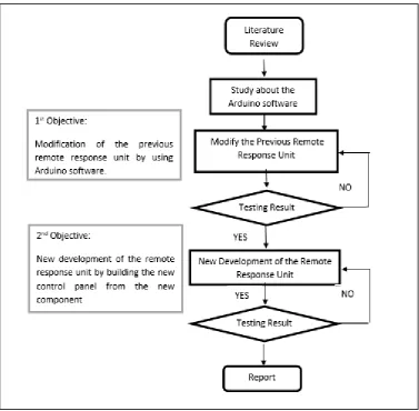
Figure 1.1: Flow chart of the methodology 5
Figure 2.1: The Schematic Diagram of the Command Flow in the Tele-Operation
System (Cui et al. 2003) 7
Figure 2.2: The Remote-Controlled Arm Robot (Computing 2013) 8 Figure 2.3: The Undersea Vehicle Jason (Cui et al. 2003) 9 Figure 2.4: The Basic Wave Transformation (Cui et al. 2003) 11 Figure 2.5: The Supervisory Control used in Teleoperation Systems (Cui et al. 2003)
12 Figure 2.6: The Overall Nonlinear Adaptive Control System (Cui et al. 2003) 12 Figure 2.7: The Neuro-Controller Model (Cui et al. 2003) 13 Figure 2.8: The Overall System of the Robot Arm (Cui et al. 2003) 14 Figure 2.9: The Sample Arduino Tool ‘Sketch’ 15 Figure 2.10: The Process Flow for Vehicle Based on Intel Galileo Platform (Sumalan
et al. 2016) 16
Figure 3.1: Flow chart of the Current Progress of the Project 18 Figure 3.2: The interface of the Arduino Integrated Arduino Development (IDE) 19 Figure 3.3: The List of the Examples in the Arduino Software (IDE) 20 Figure 3.4: The Example Sketch of the Blink 21 Figure 3.5: The Existing Remote Response Unit that have Problem 22
Figure 3.6: The Arduino Uno Board 22
Figure 3.7: The PS2 Controller (New and Used PlayStation 2 Controllers, Cables,
Memory Cards, and Accessories,2016) 23
Figure 3.8: The SKPSW-TX Transmitter 24
Figure 3.9: The 8-Channel 5V Relay Module 24
Figure 3.10: Male and Female Wire 25
xii
Figure 4.1: The Wire Connector 28
Figure 4.2: The Process of Wiring 29
Figure 4.3: The Fixed Remote Response Unit 30
Figure 4.4: The Fixed Main Coding in the Arduino (IDE) Software 30 Figure 4.5: The Plastic Board with The Equipment 31 Figure 4.6: The Completed Circuit of Arduino Project 32 Figure 4.7: The Completed Wiring in the Board 33
Figure 4.8: The Analog Value 39
Figure 4.9: The Complete Set of the Control Panel System 40 Figure 4.10: The Simulation Result of the Control Panel System 41 Figure 4.11: The Two Latest Modified Case of the Remote Response Unit 41 Figure 4.12: The Wire Connection to the Solenoid 42
Figure 4.13: The Complete Mini Robot 42
Figure 4.14: The Indicator Sign when the PS 2 Controller is Pressed 43 Figure 4.15: The Assigned Movement of the Mini Robot in the PS2 Controller 43 Figure 4.16: The PS2 Controller with the Transmitter and Its Case 44 Figure 4.17: The Flowchart of Overall Operation of the Arduino Remote Response
xiii
LIST OF TABLES
TABLES PAGE
xiv
LIST OF ABBREVIATION
LED Light-Emitting Diode PS2 Play Station 2
IDE Integrated Development Arduino
V Voltage
VCC Positive Supply Voltage GND Ground
1
INTRODUCTION
1.1 Backgrounds
Remote controls system is now widely used in many industry and it became essential for every human being. Nowadays, the remote-control capability built in many devices such as toys cars, video game consoles and ceiling fans. Remote controls allowed us to perform many tasks that would be difficult and dangerous. Remote control works by sending signal over a frequency through transmitter to the model that being controlled. The transmitter is the component used the send signal of the command from the board to the model.
For the last few years, human tend to use remote control system for other commercial use. Remote control system in many technical machine helps people to perform security tasks, building maintenance and construction. There is some development of the robotics technology which use remote control system to operate. This technology has emerged drastically now in order to decrease the need of human power. It also helps us to perform a difficult and dangerous task. For example, the remote-controlled excavator that operate in inclined and dangerous area can be controlled by the human from long range. This will make the human to deal with any situation they may encounter autonomously. (Nathan Chandler,2011)
2
instance, the robot could be built for construction work such as lifting the heavy objects or build the building wall. This will make the human less work and safe from performing dangerous task. In chemical industry, the robot can be used to lift and move the chemical objects which hazardous for human. (” How do remote controlled toys work?”,2016)
The tele-operation excavator using a human arm also was developed to perform the task like digging, material handling, demolition, general grading and mining. This resulting in positive effect for those don’t have experience to operate and manipulate a mechanical excavator. They do not need a long learning process to gain skills and knowledge required in operating the overall excavator motion. Apart from that, they also do not need to operate the excavator at the dangerous place such as the inclined hill which can lead to instability of the excavator. This tele-operation excavator used the Bluetooth wireless communication as the connection between operator and excavator. In long range, the operator can simply give the command to the excavator. So, there is no potential risk of accident involved for the operator. (Kim et al. 2009)
1.2 Problem Statement
There is problem in developing the program that can control the electro- pneumatic actuator as the program provide many alternative ways to established code. The program need to be established by creating the command system for remote response unit. There is also problem in creating the command system as there is lot of coding that need to be learned to get a fully complete function of the remote response unit.
3 1.3 Objective
The objectives of this project are as follows:
1. To modify electro-pneumatic actuator controller programming for the previous remote response unit.
2. To develop a new complete control system platform for the remote response unit.
1.4 Scope of Project
The scopes of this project are:
1. To program electro-pneumatic actuator controller for mini robot by using Arduino software. (objective 1)
2. To build a control panel for control system platform. (objective 2) 3. To survey and buy components to build the control panel. (objective 2) 4. To implement the failure mode and effect analysis on the project.
1.5 General Methodology
The actions that need to be carried out to achieve the objectives in this project are listed below.
1. Literature review
Journals, articles, or any materials regarding the project will be reviewed.
2. Software study
The Arduino software need to be practice commonly by studying the tutorials in YouTube.
4
The coding for the remote-controlled electro-pneumatic actuator need to be established in the Arduino software in order to get the exact output.
4. Testing
Testing will be made based on the coding input from the Arduino software to the board by testing it.
5. New panel development
New panel of the remote response unit will be built
6. Report writing
A report on this study will be written at the end of the project.
5
Figure 1.1: Flow chart of the methodology
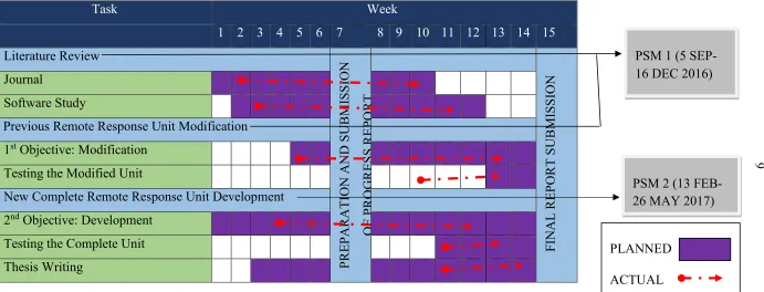
6 Table 1.1: The Gantt Chart for PSM 1 and PSM 2
No Task Week
1 2 3 4 5 6 7 8 9 10 11 12 13 14 15 1.0 Literature Review
PR EP ARATI ON AN D SUB MISS IO N OF P R OG R ES S R EP OR T F IN AL R EP ORT S UB MISS IO N
1.1 Journal
1.2 Software Study
2.0 Previous Remote Response Unit Modification
2.2 1st Objective: Modification
2.3 Testing the Modified Unit 3.0 New Complete Remote Response Unit Development
3.1 2nd Objective: Development
3.2 Testing the Complete Unit
3.3 Thesis Writing
PSM 1 (5 SEP-16 DEC 20SEP-16)
PSM 2 (13 FEB-26 MAY 2017)
PLANNED
7
LITERATURE REVIEW
2.1 Introduction of Teleoperation System Control
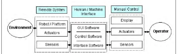
[image:22.595.145.495.487.594.2]Machine that enables a human operator to move about, sense and mechanically manipulate objects at a distance is called tele-operator. Most generally any machine which can perform a person’s mechanical action beyond her reach is called tele-operator. One of the subclass of the tele-operator is tele-robot. It is a robot which can receive a command from a human operator at specific distance. The transmission of command input through the installed sensors or other control mechanisms can make the robot to perform live actions at a distant environment. The transmission process take place in between sensors and effectors with the support of the human operator to communicate with both. Whereas, teleoperation is a mechanism in which operation of robot take place using human intelligence. This operation need a suitable adequate human-machine interface that can be easy to handle. Figure 2.1 below shows the schematic diagram of the command flow in the tele-operation system (Cui et al. 2003).
Figure 2.1: The Schematic Diagram of the Command Flow in the Tele-Operation System (Cui et al. 2003)
8
[image:23.595.143.496.235.433.2]service. Based on the International Federation of Robotics (IFR), service robot is defined as a robot which operates on semi or fully automatic to perform services useful to the well-being of humans and equipment (Yusoff et al. 2012).Hence, the main function of the teleoperation system is to help human to perform and accomplish complex or difficult tasks in hazardous and less structured environments, such as space, nuclear plants, battlefield, surveillance, and underwater operations. Figure 2.2 below shows the remote-controlled arm robot (Computing 2013).
Figure 2.2: The Remote-Controlled Arm Robot (Computing 2013)
2.2 Teleoperation Application
The application of teleoperation increasing rapidly because of the easy access to the Internet and other related technologies. Nowadays, almost all sector provides dangerous task to the human. This force human to use other equipment especially the tele-operated machine to perform this kind of task. Teleoperation system is a kind of task which need a continuous interaction between the human operators, tele-operator system and the environment in order to make the system run properly.
2.2.1 Undersea Application
9
[image:24.595.143.496.213.445.2]the human to accomplish the task completely without the help advanced technology like tele-operated machine. Teleoperation used in the undersea application mainly for inspection to know the real situation happening beneath the sea. Figure 2.3 below shows the undersea vehicle Jason which is used to locate the Titanic ship that sink under the sea. This vehicle developed by the Argo-Jason, so the vehicle is named after him (Cui et al. 2003).
Figure 2.3: The Undersea Vehicle Jason (Cui et al. 2003)