Intelligent medical device integration with real time operating system : a thesis submitted to the School of Engineering in partial fulfilment of the requirements for the degree of Master of Engineering, Department of Electronics and Computer Syetem [i e
83
0
0
Full text
(2) Intelligent Medical Device Integration with Real Time Operating System. by © Zaid Jan. A thesis submitted to the School of Engineering in partial fulfilment of the requirements for the degree of Master of Engineering. Department of Electronics and Computer Syetem Engineering at Massey University, [Albany], New Zealand. April 2009.
(3)
(4) Abstract Many commercial devices now being produced have the ability to be remotely monitored and controlled. This thesis aims to develop a generic platform that can easily be extended to interface with many different kinds of devices for remote monitoring and control via a TCP/IP connection. The deployment will be concentrated on Medical devices but can be extended to all serial device interfaces. The hardware to be used in the development of this platform is an ARM Cortex M3 based Micro-Controller board which has to be designed to meet the requirement set by the Precept Health the founder of this platform. The design was conducted at Massey University in collaboration with senior engineer from the company. The main task in achieving the aim was the development of the necessary software layers to implement remote monitoring and control. The eCosCentric real-time embedded operating system was used to form a generic base for developing applications to monitor and control specific devices. The majority of the work involved in this project was the deployment of the operating system to the Micro-Controller. During the development process, several hardware issues were discovered with the Ethernet interface and were corrected. Using the generic platform, an application was developed to allow the reading of Bi-Directional pass through a communication protocol from 4 isolated serial input channels, to an Ethernet channel using TCP protocol.. iii.
(5) Acknowledgments The success of this project would not have been possible without the guidance, assistance and dedication of a number of people. I would like to give many thanks to my supervisor, Dr Tom Moir for his advice, feedback and guidance and also for giving me the opportunity to conduct this thesis.. I would like to thank Tony Blomfield for offering the opportunity and funding to develop this platform, and for his on-going support throughout the project. His knowledge and experience has helped me to avoid many pitfalls along the way. Furthermore I would like to thank Nestor and Philip from eWatch for all their help and guidance through-out the project. Special thanks to Philip for explaining some off the most complex parts of the real time operating system and avoid some of the pitfalls which I have encountered during the development cycle. Finally, I would like to thank my family for their ongoing support, and I am certain they are happier than me that it’s all over!. iv.
(6) Contents Abstract. iii. Acknowledgments. iv. List of Tables. x. List of Figures. xi. 1 Introduction. 1. 1.1. Thesis Overview . . . . . . . . . . . . . . . . . . . . . . . . . . . . . . . . .. 1. 1.2. Design Specification . . . . . . . . . . . . . . . . . . . . . . . . . . . . . . .. 3. 1.2.1. Requirements . . . . . . . . . . . . . . . . . . . . . . . . . . . . . . .. 3. 1.2.1.1. Understanding of eCosCentric . . . . . . . . . . . . . . . .. 3. 1.2.1.2. Development Setup . . . . . . . . . . . . . . . . . . . . . .. 4. Constraints . . . . . . . . . . . . . . . . . . . . . . . . . . . . . . . .. 5. 1.3. Major Contributions . . . . . . . . . . . . . . . . . . . . . . . . . . . . . . .. 6. 1.4. Thesis Outline . . . . . . . . . . . . . . . . . . . . . . . . . . . . . . . . . .. 7. 1.2.2. 2 Background and Literature Review. 8. 2.1. Embedded System Overview . . . . . . . . . . . . . . . . . . . . . . . . . . .. 8. 2.2. Embedded Computing Design . . . . . . . . . . . . . . . . . . . . . . . . . .. 9. 2.2.1. Different operating system solution . . . . . . . . . . . . . . . . . . .. 9. 2.2.2. Managing embedded devices. . . . . . . . . . . . . . . . . . . . . . .. 11. 2.3. Hardware . . . . . . . . . . . . . . . . . . . . . . . . . . . . . . . . . . . . .. 13. 2.4. Programming embedded devices. . . . . . . . . . . . . . . . . . . . . . . . .. 13. 2.5. Medical Device Safety Requirements . . . . . . . . . . . . . . . . . . . . . .. 15. 2.5.1. Software Safety . . . . . . . . . . . . . . . . . . . . . . . . . . . . . .. 15. 2.5.2. Hardware Safety . . . . . . . . . . . . . . . . . . . . . . . . . . . . .. 16. v.
(7) 3 Hardware design 3.1. Hardware Architecture and Schematic Design . . . . . . . . . . . . . . . . .. 17. 3.1.1. Central Processing Unit CPU . . . . . . . . . . . . . . . . . . . . . . .. 18. 3.1.1.1. STM32F103 ARM Cortex M3 Thumb2 Processor . . . . .. 19. 3.1.1.2. Interrupt Controller . . . . . . . . . . . . . . . . . . . . . .. 19. 3.1.1.3. Timer/Counter . . . . . . . . . . . . . . . . . . . . . . . . .. 19. 3.1.1.4. USART’s . . . . . . . . . . . . . . . . . . . . . . . . . . . .. 20. 3.1.1.5. On-Chip SRAM . . . . . . . . . . . . . . . . . . . . . . . .. 20. 3.1.1.6. Bus Matrix Interface. . . . . . . . . . . . . . . . . . . . . .. 20. 3.1.1.7. Programmable Input Output PIO . . . . . . . . . . . . . .. 20. 3.1.1.8. Watchdog Timer . . . . . . . . . . . . . . . . . . . . . . . .. 21. 3.1.2. Power Supply(Switch Mode) . . . . . . . . . . . . . . . . . . . . . .. 21. 3.1.3. Serial port with optical isolation . . . . . . . . . . . . . . . . . . . .. 22. 3.1.4. Ethernet Controller (Wiznet W5100) . . . . . . . . . . . . . . . . . .. 23. 3.1.5. Micro SD Card Storage . . . . . . . . . . . . . . . . . . . . . . . . .. 24. 3.1.6. JTAG . . . . . . . . . . . . . . . . . . . . . . . . . . . . . . . . . . .. 25. 3.1.6.1. JTAG Adapter . . . . . . . . . . . . . . . . . . . . . . . . .. 26. Final Implementation of the Prototype Boards . . . . . . . . . . . .. 27. Printed Circuit Board Design (pcb) . . . . . . . . . . . . . . . . . . . . . . .. 30. 3.2.1. Overview procedure . . . . . . . . . . . . . . . . . . . . . . . . . . .. 31. 3.2.2. PCB Design Considerations . . . . . . . . . . . . . . . . . . . . . . .. 32. 3.2.2.1. Trace width and trace clearance Requirements . . . . . . .. 33. 3.2.2.2. Type of vias on the PCB . . . . . . . . . . . . . . . . . . .. 33. 3.2.2.3. Floorplanning . . . . . . . . . . . . . . . . . . . . . . . . .. 33. 3.2.2.4. PCB Mask layer design consideration . . . . . . . . . . . .. 34. 3.1.7 3.2. 17. 3.2.3. PCB Implementation. . . . . . . . . . . . . . . . . . . . . . . . . . .. 4 Software Design 4.1. 34 37. Real-time Operating System eCosCentic . . . . . . . . . . . . . . . . . . .. 37. 4.1.1. eCosCentric Source Tree Roadmap . . . . . . . . . . . . . . . . . . . .. 38. 4.1.2. The eCosCentric Architecture . . . . . . . . . . . . . . . . . . . . . .. 39. 4.1.3. Hardware Abstraction Layer. . . . . . . . . . . . . . . . . . . . . . .. 39. HAL Start-up . . . . . . . . . . . . . . . . . . . . . . . . .. 41. The Redboot ROM Monitor . . . . . . . . . . . . . . . . . . . . . . .. 42. 4.1.3.1 4.1.4. vi.
(8) 4.1.4.1. Redboot feature . . . . . . . . . . . . . . . . . . . . . . . .. 43. 4.1.4.2. Virtual vector calling interface . . . . . . . . . . . . . . . .. 44. Kernel . . . . . . . . . . . . . . . . . . . . . . . . . . . . . . . . . . .. 44. 4.1.5.1. Kernel Boot Procedure . . . . . . . . . . . . . . . . . . . .. 45. 4.1.5.2. Startup Modes . . . . . . . . . . . . . . . . . . . . . . . . .. 45. 4.1.5.3. Schedulers . . . . . . . . . . . . . . . . . . . . . . . . . . .. 47. 4.1.5.4. Interrupt Handling Mechanism . . . . . . . . . . . . . . . .. 47. 4.1.5.5. Exception Handling . . . . . . . . . . . . . . . . . . . . . .. 48. Thread Synchronisation . . . . . . . . . . . . . . . . . . . . . . . . .. 49. 4.1.6.1. Mutex . . . . . . . . . . . . . . . . . . . . . . . . . . . . . .. 50. 4.1.6.2. Semaphores . . . . . . . . . . . . . . . . . . . . . . . . . . .. 50. 4.1.6.3. Flags . . . . . . . . . . . . . . . . . . . . . . . . . . . . . .. 51. 4.1.6.4. Spinlocks . . . . . . . . . . . . . . . . . . . . . . . . . . . .. 51. 4.1.6.5. Condition Variables . . . . . . . . . . . . . . . . . . . . . .. 51. 4.1.6.6. Message Boxes . . . . . . . . . . . . . . . . . . . . . . . . .. 51. i/O Control System . . . . . . . . . . . . . . . . . . . . . . . . . . .. 51. 4.1.7.1. I/O Subsystem . . . . . . . . . . . . . . . . . . . . . . . . .. 52. 4.1.7.2. Device Drivers . . . . . . . . . . . . . . . . . . . . . . . . .. 53. Network Support . . . . . . . . . . . . . . . . . . . . . . . . . . . . .. 53. 4.1.8.1. TCP/IP Stack . . . . . . . . . . . . . . . . . . . . . . . . .. 53. 4.1.8.2. Supported Protocol . . . . . . . . . . . . . . . . . . . . . .. 54. Configuration Tool . . . . . . . . . . . . . . . . . . . . . . . . . . . .. 55. 4.1.10 eCosCentric building process . . . . . . . . . . . . . . . . . . . . . .. 56. 4.1.11 eCosCentric Support . . . . . . . . . . . . . . . . . . . . . . . . . . .. 58. Implemtation of Micro-Controller Bootstrap . . . . . . . . . . . . . . . . . .. 58. 4.2.1. Boot Table . . . . . . . . . . . . . . . . . . . . . . . . . . . . . . . .. 59. 4.2.2. Micro Controller Peripheral Initalisation . . . . . . . . . . . . . . . .. 59. 4.2.2.1. PIO . . . . . . . . . . . . . . . . . . . . . . . . . . . . . . .. 59. 4.2.2.2. Watchdog . . . . . . . . . . . . . . . . . . . . . . . . . . . .. 59. 4.2.2.3. USART’s . . . . . . . . . . . . . . . . . . . . . . . . . . . .. 59. 4.2.3. Copy Program Image to SRAM . . . . . . . . . . . . . . . . . . . . .. 60. 4.2.4. Set Register to Define Values . . . . . . . . . . . . . . . . . . . . . .. 60. Implementation of eCosCentric . . . . . . . . . . . . . . . . . . . . . . . . .. 60. 4.3.1. 60. 4.1.5. 4.1.6. 4.1.7. 4.1.8. 4.1.9. 4.2. 4.3. Redboot . . . . . . . . . . . . . . . . . . . . . . . . . . . . . . . . . . vii.
(9) 4.3.2. 4.3.3. 4.4. HAL Port . . . . . . . . . . . . . . . . . . . . . . . . . . . . . . . . .. 61. 4.3.2.1. Structure of the Port . . . . . . . . . . . . . . . . . . . . .. 61. 4.3.2.2. Platform Initialisation . . . . . . . . . . . . . . . . . . . . .. 61. 4.3.2.3. Memory Layout . . . . . . . . . . . . . . . . . . . . . . . .. 62. 4.3.2.4. CDL-File . . . . . . . . . . . . . . . . . . . . . . . . . . . .. 63. 4.3.2.5. Modification of the eCosCentric database . . . . . . . . .. 64. Implementation of specific drivers. . . . . . . . . . . . . . . . . . . .. 64. 4.3.3.1. Ethernet Controller Wiznet W5100 . . . . . . . . . . . . . .. 65. 4.3.3.2. Serial interface Driver . . . . . . . . . . . . . . . . . . . . .. 65. Development of Configuration Utility . . . . . . . . . . . . . . . . . . . . . .. 65. 4.4.1. 66. Board Configuration utility . . . . . . . . . . . . . . . . . . . . . . .. 5 Development Setup 5.1. 5.2. 68. Software Environment Setup . . . . . . . . . . . . . . . . . . . . . . . . . .. 68. 5.1.1. getting eCosCentric Source . . . . . . . . . . . . . . . . . . . . . . .. 68. 5.1.2. Getting eCosCentric Configuration Tool Ver2 . . . . . . . . . . . . .. 69. 5.1.3. Eclipse IDE . . . . . . . . . . . . . . . . . . . . . . . . . . . . . . . .. 70. 5.1.4. OpenOCD . . . . . . . . . . . . . . . . . . . . . . . . . . . . . . . . .. 70. Supported Medical Device . . . . . . . . . . . . . . . . . . . . . . . . . . . .. 71. 6 Demonstration and Testing. 72. 6.1. Procedure Steps. . . . . . . . . . . . . . . . . . . . . . . . . . . . . . . . . .. 73. 6.2. Evaluation . . . . . . . . . . . . . . . . . . . . . . . . . . . . . . . . . . . . .. 76. 7 Conclusions And Future Work. 77. References. 79. Appendix. 84. A Schemtics . . . . . . . . . . . . . . . . . . . . . . . . . . . . . . . . . . . . . . . A.1 Main Board. 84. . . . . . . . . . . . . . . . . . . . . . . . . . . . . . . . . .. 84. B Application Source Code . . . . . . . . . . . . . . . . . . . . . . . . . . . . . .. 85. B.1 Setip Application. . . . . . . . . . . . . . . . . . . . . . . . . . . . . . .. 85. B.2 Virtual serial port . . . . . . . . . . . . . . . . . . . . . . . . . . . . . .. 90. C Embedded Firmeware . . . . . . . . . . . . . . . . . . . . . . . . . . . . . . . .. 98. C.1 Linking and building the application . . . . . . . . . . . . . . . . . . . .. 98. viii.
(10) C.2 RedBoot Configuration File . . . . . . . . . . . . . . . . . . . . . . . . .. 99. C.3 Ethernet driver W5100 . . . . . . . . . . . . . . . . . . . . . . . . . . .. 101. ix.
(11) List of Tables 3.1. Code space required by different Ethernet controller using SPI interface . .. 23. 4.1. I/O API . . . . . . . . . . . . . . . . . . . . . . . . . . . . . . . . . . . . . .. 52. x.
(12) List of Figures 3.1. Cortex arch M3 . . . . . . . . . . . . . . . . . . . . . . . . . . . . . . . . . .. 18. 3.2. Switch mode power supply . . . . . . . . . . . . . . . . . . . . . . . . . . . .. 21. 3.3. Isolated serial port . . . . . . . . . . . . . . . . . . . . . . . . . . . . . . . .. 23. 3.4. Ethernet controller . . . . . . . . . . . . . . . . . . . . . . . . . . . . . . . .. 24. 3.5. Implementation of the Micro-SD card . . . . . . . . . . . . . . . . . . . . .. 25. 3.6. JTAG interface . . . . . . . . . . . . . . . . . . . . . . . . . . . . . . . . . .. 25. 3.7. JTAG adapter interface . . . . . . . . . . . . . . . . . . . . . . . . . . . . .. 26. 3.8. Top layer of the Final Prototype Board . . . . . . . . . . . . . . . . . . . .. 27. 3.9. Bottom layer of the Final Prototype Board . . . . . . . . . . . . . . . . . .. 27. 3.10 Final implementation of the JTAG Adapter . . . . . . . . . . . . . . . . . .. 28. 3.11 Full picture overview of the system . . . . . . . . . . . . . . . . . . . . . . .. 28. 3.12 Initial design of this project - top layer [4 layer board] . . . . . . . . . . . .. 29. 3.13 Initial design of this project - Bottom layer [4 layer board] . . . . . . . . . .. 29. 3.14 Top and bottom layout of the main board . . . . . . . . . . . . . . . . . . .. 30. 3.15 Top and bottom layout of the JTAG adapter . . . . . . . . . . . . . . . . .. 31. 3.16 Top layout of the initial board . . . . . . . . . . . . . . . . . . . . . . . . .. 34. 3.17 Bottom layout of the initial board . . . . . . . . . . . . . . . . . . . . . . .. 35. 3.18 Ground plane of the initial board (inner layer) . . . . . . . . . . . . . . . .. 35. 3.19 Power plane layout of the initial board (inner layer) . . . . . . . . . . . . .. 36. 4.1. eCosCentric File Directory Roadmap . . . . . . . . . . . . . . . . . . . . . .. 38. 4.2. Hardware Abstraction Layer[27] . . . . . . . . . . . . . . . . . . . . . . . . .. 39. 4.3. eCosCentric startup procedure[27] . . . . . . . . . . . . . . . . . . . . . . .. 41. 4.4. Redboot ROM Monitor Architecture . . . . . . . . . . . . . . . . . . . . . .. 43. 4.5. Kernel stratup procedure . . . . . . . . . . . . . . . . . . . . . . . . . . . .. 45. 4.6. eCosCentric exception handling and execution flow[27] . . . . . . . . . . . .. 49. 4.7. The eCosCentric I/O subsystem Architecture[27] . . . . . . . . . . . . . . .. 52. xi.
(13) 4.8. Network Architecture. . . . . . . . . . . . . . . . . . . . . . . . . . . . . . .. 53. 4.9. eCosCentric GUI Configuration Tools . . . . . . . . . . . . . . . . . . . . .. 55. 4.10 eCosCentric Package Database Structure . . . . . . . . . . . . . . . . . . . .. 56. 4.11 eCosCentric Build Process[27] . . . . . . . . . . . . . . . . . . . . . . . . . .. 57. 4.12 Configuration utility . . . . . . . . . . . . . . . . . . . . . . . . . . . . . . .. 66. 5.1. OpenOCD layers and interface . . . . . . . . . . . . . . . . . . . . . . . . .. 71. 6.1. Board Configuration Utility . . . . . . . . . . . . . . . . . . . . . . . . . . .. 73. 6.2. Serial Terminal Program Configuration . . . . . . . . . . . . . . . . . . . . .. 74. 6.3. Network Terminal Program Configuration . . . . . . . . . . . . . . . . . . .. 74. 6.4. Received Data by Network Terminal Program . . . . . . . . . . . . . . . . .. 75. 6.5. Device Terminal Program . . . . . . . . . . . . . . . . . . . . . . . . . . . .. 76. xii.
(14) Chapter 1. Introduction 1.1. Thesis Overview. eCosCentric is an open source real-time operating system developed by Redhat and its user community. It’s like other conventional operating systems, seeks to reduce the burden of application development by providing convenient abstractions of physical devices and highly tuned implementations of common functions [15]. eCosCentric has been designed in such a way that a small resource footprint can be constructed. It is extremely configurable and allows developers to select components that satisfy basic application requirements. eCosCentric uses compile-time control methods, along with selective linking, provided by the GNU linker, to give the developer control of its behaviour, allowing the implementation itself to be built for the specific application for which it is intended. The motivation for this master thesis arose from the need to develop a cheap device with a network interface and software support for the TCP/IP protocol. Since the computing power and memory resources were below the limit to run Embedded Linux, the natural decision is to run the much more economical real-time operating system eCosCentric. This document gives advice for further developments related to the build of the mentioned cheap network device and describes the conducted works related with the porting of eCosCentric to a custom hardware platform. During the conduction of this project several major aims were strived. The following list gives a summarised overview about the aims and objectives. • Custom hardware design • Evaluation of the eCosCentric operating system regarding architecture, capabilities, and footprint.. 1.
(15) • Setup of the software development system • Porting of eCosCentric to the target hardware • Implementation of required drivers • Integration of the HAL port and new drivers into the eCosCentric component framework • Application development The initial step of the project was the reading of relevant literature in the space of embedded system. All required software components for host and target development has been obtained from the eCosCentric distributor’s Internet resources. The host PC, was provided by Dr Tom Moir, the project supervisor. The basic hardware for this project was an Ubuntu Sarge operating PC. The interface between the host and the target board was established using the JTAGKEY-Tiny from Amontec [17]. The required software connection between host and target was established using OpenOCD [33] which is a free JTAG software debugger for the ARM Coretex, ARM7 and ARM9 CPUs. Several guides, all referenced in the bibliography, were considered to port the system to the custom hardware. Furthermore the eCosCentric mailing list gave supporting answers to upcoming questions. The First major task of the thesis was to design the hardware that will meet the requirement set by the sponsor (Precept Health); the 2nd major task was the porting of the eCosCentric HAL (Hardware Abstraction Layer) to the custom hardware. This goal has been accomplished successfully. The three aimed interface drivers the serial [RS232], Ethernet and Micro SD card driver have been implemented and tested successfully. While the port of the Ethernet driver for the eCosCentric operating system was being implemented several hardware issues were discovered with the Ethernet controller and were corrected. Ethernet driver need some further work to be entirely integrated into the eCosCentric system. Thereby the developed routines of the Ethernet driver have to be debugged and tested to provide the demanded functionality. Nevertheless all drivers can be selected and configured using the eCosCentric Configuration Tool. The conducted HAL port and the drivers have been entirely adapted to the eCosCentric component framework. The implemented applications RedBoot example illustrates the functionality of the eCosCentric HAL, the serial driver and the usage of the GPIO ports of the STM3 MCU.. 2.
(16) 1.2. Design Specification. The design of this system aims to integrate medical devices such as ECG, ventilator, drugs pumps, etc..., with real-time reconfigurable operating system capabilities. To fulfil future requirements of a medical devices integration platform, commonly used features from existing providers such as Philips, EMG, should also be incorporated for real-time data analysis. The performance throughout the entire system should to be maximized in order to satisfy the needs of future developments.. 1.2.1. Requirements. The design of a new platform that will support multi serial interface that will integrate medical devices should ideally consist of the following: • Design new hardware platform that support medical device integration with medical standards [certification] • Evaluation of the eCosCentric operating system, regarding architecture, capabilities, and footprint • Setup of the hardware and software development system • Porting of eCosCentric to the target hardware • Implementation of required drivers (Ethernet, Micro SD card, 4 Serial ports) • Integration of the HAL port and new drivers in the eCosCentric component framework • Application development • Within the scope of this master thesis only free, open-source software packages have been used in this project except for the electronics design package (Altium). 1.2.1.1. Understanding of eCosCentric. A detailed comprehension of the eCosCentric operating system is a fundamental requirement for the process of the whole implementation. The architecture of eCosCentric has to be analysed and the crucial components for the single steps of the eCosCentric implementation have to be mentioned. One of the core components of the eCosCentric operating system is the Hardware Abstraction Layer (HAL). This layer builds together with the driver components the only hardware dependent part of eCosCentric. Upper layers can use the 3.
(17) standardised interface of the HAL to access hardware functionality. Hence the attributes of this module have to be described properly. Interrupt and exception handling are important matters concerning the analysis of an operating system. These functionalities have to be investigated and reflected. Since the final aim of a port is the implementation of own applications the insight process of own tasks has to be described. Applications running on eCosCentric are built in threads, the handling of this software component has to be analysed The core component of each operating system is the Kernel. This module deals with timing matters and offers scheduling mechanisms for thread administration. The attributes and configuration options of the eCosCentric scheduler have to listed and explained. Furthermore all necessary attributes of eCosCentric concerning the port and the implementation have to be given. 1.2.1.2. Development Setup. The bases of each development setup are the software packages, the host and target hardware components, and the interface components between host and target. Primarily all used components have to be mentioned and in addition nontrivial installation and configuration steps have to be explained.. Hardware. The target hardware needs to provide a sufficient amount of memory. It has to be investigated which footprints are typical for eCosCentric. Since an ARM Cortex M3 [STM32F103RE] Micro-controller will be used in future developments this type of processor has to be kept in mind. It is essential that the platform offers the general interfaces as SPI, CAN, Serial, and I2C. For debugging purposes a JTAG interface has to be provided. Debugging has to be conducted using a hardware debugger. A suggestion is the Amontec JTAGkey-Tiny which is a programmable JTAG interface able to emulate specific USB to JTAG interfaces. For the ongoing work the target platform design and layout has to be analysed and determining attributes for the implementation progress and the driver development have to be discussed.. 4.
(18) Software. As already mentioned eCosCentric is a free, open source operating system. The open source thought has to be kept from the beginning of the master thesis till the final report. This means that all software and tools which are used have to be free. The host computer for development has to be a PC running Ubuntu Linux. Concrete installation steps and configuration settings of the host operating system have not been described since the host hardware is likely to be individual for each future developer. However the used software packages have to be listed together with their current versions. The setup of the development and debug environment for the eCosCentric port, the driver development and the design of applications has to described in detail but within the scope of thesis. If the installation of certain software excesses the scope of the thesis further documentation has to be offered.. Implementation of eCosCentric. The first major requirement is the porting of the eCosCentric HAL to the target hardware. Therefore the porting progress has to be analysed and a decision about the variant of the port has to be made. The HAL must initialize the target hardware containing CPU, memory, serial interface and GPIO setup. Furthermore the implementation has to be fitted into the eCosCentric component framework. This makes the new board selectable and configurable using the eCosCentric Configuration Tool. Drivers for the Ethernet and serial communication, the external storage access have to be implemented. In particular the RS232 driver has to allow access to a bus sending and receiving messages. Full handshaking abilities, i.e. hardware filtering of messages, are not required. As a first ROM application Redboot has to be built and run on the target hardware. The GPIO abilities have to be demonstrated using a RAM application using threads.. 1.2.2. Constraints. Time and budgetary constraints limit the range of devices that can be incorporated into the hardware platform. Thus the primary goal is to obtain the best possible performance within the given constraints and at minimal cost. These constraints are:. 5.
(19) Power Supply: As the device will be safety critical so proper switch mode power supply have to be designed according to the medical standard [it must provide total isolation to all devices], power consumption should be minimized which mean devices that are not in use dose not consume power.. PCB size: As the target device is intended for a stand still platform such as a bedside device, the size of the board must be kept to a minimum to reduce the cost of PCB board manufacturing. The current dimensions of the board is 100mm x 70mm. A much larger board would become too costly to produce.. PCB Layers: Many PCB manufacturers will manufacture PCB’s with up to six layers. Locating a company willing to do small run of prototype is quite difficult and costly in particularly in New Zealand, PCBCART prototype which is located in China are the perfect solution, due to their price and quality of work. The design consists of two layer.. Medical certification: The RoHS (Restriction on Hazardous Substances) directive was enforced in the EU (European Union) on July 1st 2006 [34], with other countries around the world expected to follow suit in the following years. Amongst other things, this directive prohibits the production or import of electronics goods containing lead within the EU. This has caused a variety of production issues in the global electronics industry as all manufacturers require retooling to accommodate lead-free processes.. 1.3. Major Contributions. The major contribution of this project are: • The architectural and schematic design of the Medical Device Adapter; • Sourcing RoHS-compliant parts for the design; • The eCosCentric driver support; 1. ARM Cortex M3 thumb 2 STM32 configuration 2. STM32 Memory-Mape I/O access 3. Wiznet Ethernet Driver 4. RS232 device driver 6.
(20) 5. Micro SD card driver [external storage] • performance and optimization of data transfer from the Ethernet to CPU. 1.4. Thesis Outline. Chapter 1 Offers a brief outline of the project, its motivations and its specification.. Chapter 2 Presents background information in the area of embedded systems and also covers the hardware, software requirement of medical device development.. Chapter 3 Documents the approach taken to the hardware design of the Medical Device Adapter.. Chapter 4 Describes the software drivers and interfaces written for the board.. Chapter 5 Describe the approach taken to setting up the software environment.. Chapter 6 Summarizes the project and discusses future work on the system that will follow.. 7.
(21) Chapter 2. Background and Literature Review 2.1. Embedded System Overview. Today embedded systems control lots of different tasks implementing more powerful and complex device. They are integrated and plugged in many kinds of machines, but also taking an stand alone application as they have been implemented in devices like PDAs, mobile phones and MP3 players. One major sector of embedded devices from the beginning has been the devices in industry. With an external controller an industry machine with a proper interface can easily be connected to local area network or to internet without making any modifications to the system. The embedded controller acts as a modem like device to the end system. The collected information can then be displayed via a PC in the main controller room and the necessary settings to the end machine can be done from there. More advanced embedded devices can also include analogue or digital inputs and outputs for controlling and process the collected information before it is forwarded on. The embedded systems today can roughly be divided into high-end embedded systems and deeply embedded systems. • The high-end embedded system classification is used when a general purpose OS is stripped down and left with specific modules for specific purpose. As the different parts of embedded solutions are becoming less expensive, more and more devices classified to this category. Examples of these devices are router, personal digital assistant; PDA and todays mobile phones. • Deeply embedded systems are designed for particular application. They need to be very compact, integrated with only few basic functions. These device are designed with a minimal operating systems and hardware layout designed for the specific purpose. 8.
(22) Examples of these devices are small controllers and devices in our everyday life like microwave, where they are embedded in [5].. 2.2. Embedded Computing Design. As components like processor and memory has become less expensive are embedded device integrated in several different kinds of device. This also means that we are able to use more processing power and memory on these devices, so they are becoming much more complex, providing more functionality. The different resources running on the device requires to be controlled by more intelligent operating system. In many simple 8-bit controllers, the tasks can be handled in a simple server loop, just by polling the different interfaces on the device. More intelligent device requires more intelligent operating system to manage all the functions that they provide. The operating systems for these devices are many times derivated from a general purpose operating system, so the barrier between embedded and general purpose operating system can be inconstant. The concept of operating system is not that clear. Usually the operating is supposed to fulfil the tasks of providing an extension to the hardware. This means that it provides layering by providing the lower level drivers for the physical chips and an API for the programmer. Operating system also provides a resource management for different applications running on that device by handling interrupts and allocating memory for applications. Operating system also gives an advantage to the programmer, as it provides some kind pf protection against programming failures for low level devices and gives a foundation where programs can run on [50].. 2.2.1. Different operating system solution. The main difference with general purpose operating system and embedded operating system is that the footprint of the embedded version should be only a part of the size that the general purpose OS takes. The difference can be seen when exploring the systems mission. The limitation of memory, processor and interfaces limit the tasks that a real embedded computer can attempt. As the system operates on a narrow, pre-designed area it provides tasks that are useful for that purpose. All tough embedded devices are designed to be beneficial solutions for specific task the barrier between these two systems is nowadays becoming more and more invisible, as the amount of memory and process power is increasing. Several companies and communities have started to develop operating system specially 9.
(23) designed for these embedded devices demands. Most of these solutions have chosen UNIX like approach to develop the system, as it holds clear solution for small simple device often without almost any external interfaces. As the market of embedded devices are growing a substantial efforts from major companies have been made to enter these markets, also with non Open Source distributions. Still regardless of the embedded OS all embedded systems are an entirety of several different layers of software providing drivers for the hardware and an interface to the end user. The eCosCentric is the most popular UNIX-like clone used today. The advantages that eCos RTOS provides are that it is royalty free solution with easy configuration and strong networking support. It has also been ported to run on embedded devices and there exists many companies providing commercial and non-commercial embedded Linux solutions. When obtaining an embedded Linux distribution it usually includes a tool chain, some ported applications, ported libraries and of course the actual kernel. The tool chain enables you to build applications or to create the image for an embedded device. Most of these are based on a standard GNU tool chain, but there also exists some packages that require proprietary tools. The applications included to the package are a set of ported applications designed especially for that solution that can be compiled to image [30]. The biggest problem with eCos in commercial usage is that the GPL rules forces companies to keep the source code available to everyone, including the competitors. The license still allows applications and device drivers to be private if they remain separate from the kernel and do not contain any other parts from programs developed under the GPL. Some companies providing Linux distributions have even provided specially designed tools to check which parts of the software have GPL violations. One example of these companies is Lineo’s GPL Compliance Tool. More problematic license in embedded devices is LGPL. In embedded device the whole application set is build in a single compact executable. To save space, the package is in many cases linked statically against the libraries. This means that the source code has to be available to all parts [49]. By dropping unnecessary modules and drivers from the general purpose kernel, it can be compiled in the size of 800Kb. Most embedded solutions are using this approach, but when adding some real-time support or supporting MMU-fewer solutions, more patching is required. The open source efforts against embedded Linux systems can be inspected from different angles depending how they are developed. One approach is to start to eliminate the unnecessary functionalities that are not required from the embedded device. One example of this stripped, small footprint operating system is uClinux. As the Linux itself can be 10.
(24) compiled to rather small package as it is, the standard Linux kernel itself can be patched against of the demands of the embedded device. Advantage if this system is that the Linux applications can be ported rather easily to this platform. Examples of these kind of solution are FreeRTOS, eCospro, AXIS and BlueCat Linux [5]. Embedded Linux is also distributed by some bigger commercial companies like Lineo, MontaVista and Red Hat. The main key behind these companies is that they provide support and professional services, a thorough documentation of their software development kits, maybe some specialized tools and systemization services. Some of these vendors, like Monta Vista provides also a real-time extension to the kernel which enables to device to have real-time performance. Two embedded solutions uClinux and eCosCentric are also focused on MMU-less processors. From these the eCosCentric provides an advantage by offering an active developer community and providing free support. It has also been ported to several different processor’s and development boards. The eCosCentric kernel and tools are also totally free so for embedded solution it does not create any extra costs.. 2.2.2. Managing embedded devices. Most common physical interfaces in embedded devices are serial and Ethernet interface. These are also in many times the only interfaces which allow physical management to be done to the device without any user interfaces like display or keyboard. From these the serial is basically used to create the end connection to the controlled machine, but at the development stage with a proper serial communication program it can also be used to connect to the embedded device. Here the host machine works as a terminal emulator for the embedded device. Serial is also often used to move the systems image to the device or to set the entire basic configuration to the board. The USB has nowadays also taken a place of acting as of connectivity interface to end device, but in embedded devices it is still quite rare. The physical Ethernet with the connectivity application enables the device to be connected to the network. The TCP/IP’s OSI model layer 4 has two protocols UDP and TCP providing the boundary between the user applications and host-layer protocols. Embedded controllers might provide several of different applications that can be used to connect and control the devices. Chapter four introduces the networking protocol provided by the eCosCentric platform. Client-server programs in embedded devices are usually run as servers or daemons, to enable the connection to be made to the device. Two most known and used program in 11.
(25) this category are Terminal Emulation, Telnet and Secure Shell, SSH. Telnet provides the ability to remotely access to an embedded device. The telnet daemon runs on an embedded device allowing transmitting the keystrokes from the remote host to the target embedded device and displays the resulting screen to back to the remote host. SSH is a more secure version for remote connectivity. The idea is the same as in telnet, but provides secure encrypted communications between the devices. For each new connection a new daemon is created which handles the exchange, encryption, authentication, command execution, and data exchange. The File transfer protocol, FTP is designed for file up- and downloading. In embedded devices it can often be used in both directions by running both a daemon and a client in an embedded device. This way we can easily place files in an embedded system and also send for example log information back to the host machine. The Simple Mail Transfer Protocol, SMTP is usually in embedded device implemented as client software. It allows mail to be sent to the remote host when an event triggers it. Usually it is used for sending scheduled information to a known host. The HTTP can be used as a web configuration, which makes it a powerful tool. The GUI of the HTTP page can be used as a virtual interface to control the device itself and the end system that it is connected to. Usually this enables only the basic set configuration to be done, but still this is extremely handy in embedded Linux as it regularly provides only a console based connection used with the predefined set of commands. The Simple network message protocol, SNMP is based on asynchronous request / response commands. It is a widely accepted protocol, providing the management of different types of networks with a simple design that causes only a small burden to the network. As it is well known, it also has an extensive range of tool support. The agent of a SNMP protocol is running as a server in each of the monitored or managed device. It provides an interface to each of these nodes by providing a data structure called a management information base, MIB. SNMP provides also an ability to easily manage all the devices distributed to the field by running special management software running on the management station. The agent on the embedded device responds to the control stations query or setting and acts on it. The protocol also enables the card to act as a proxy toward the end system by holding a specially designed for that task. The agent end is also able to send asynchronous traps to the end station when a predefined event occurs [50].. 12.
(26) 2.3. Hardware. The basic architecture in embedded device is usually the same when it is designed to provide network connectivity to the end system. They usually hold and serial interface to connect the embedded device to the end system, an Ethernet plug for network connectivity and of course a Micro-Controller Unit and some kind of system memory. The different hardware solutions usually concern the processor type, size and type of the memory and the interfaces that the device provides. When designing the hardware solution, the design goals can meet the customer markets by competing with better solution than the existing one or by getting the product to market faster than the competitor. The best substitute for devices without a hard drive is flash memory which can be designed to emulate a drive. Flash also gives an advantage of being less power consuming, faster and space efficient than standard storages in table PC’s [50]. The processors in embedded devices have two major alignments. Ones holding the Memory Management Unit, MMU and others that are designed without it. The advantages gained from the MMU are that it provides memory protection against the applications, but with precautions it is possible to run MMU-fewer versions on a smaller device for compact embedded applications. Of course it also gives a cheaper solution for designing the controller. The features that are required from the embedded devices are a possibility for long term autonomy, cost efficiency, low power consumption and general reliability. The device is to achieve reliability from the software and hardware. They are used to sense the outside world and control the device in industrial surrounding so a failure in embedded device might mean that the controlled machine is damaged. This requires a thorough testing from the hardware and the software side. The cost efficiency is also a key feature, as the devices are usually distributed to a field, a small change in the price affects significantly to the end purchasing price.. 2.4. Programming embedded devices. In spite of the usage of embedded device, the design goal is to try to put more computing power using cheaper CPU’s. The amount of memory is often limited to few kilobytes so the decision of what are the different applications integrated with the embedded OS are carefully to be taught through. The embedded device, at least on industrial usage, can stand alone for a long period of time so the software and hardware on the device should. 13.
(27) never fail. This undresses the device from mechanical parts that are more sensitive for failures and require more complex drivers and well tested software to be added with the OS. Unlike software designed to general purpose PC, the embedded software cannot be used in other embedded devices unless it is modified. This is because embedded devices hardware layout of the boards may differ significantly from each other. Different solutions of operating systems often consists a specific tools for compiling applications especially for that processor or board. Still addresses in memory locations and other offsets of the physical interfaces may vary and needs to be modified. Compilers many times have also options for building the code to several specific processor types. The code generated for the embedded device is compiled in the host machine, where the development tools exist. This process is called cross-compilation. It means that the host machine, regularly a normal table PC, holds the resulting tool chain that will eventually the create binaries for the target embedded machine. The main idea is that the compilation can be done in a machine with more capacity than the target platform. After the compilation the whole package including the operating system kernel and the applications are concatenated to a single package which can be loaded to the embedded machine. When developing software to embedded devices, thorough testing is required. In worst cases the stand alone device can freeze up totally by badly designed and tested software. This is why generated executable should always be first tested in a host machine, to minimize the existence of errors. Usually some modification might be needed after wards, before it can runs on a target machine. The generated code size is limited by the physical memory of the device. Also processor might do some restrictions by not having enough processing power to run several complex programs at the same time. Programming languages used in embedded devices is usually done with assembly as a low level language and with a C as an application level language. Both of these languages allow programmers to access directly to hardware and not have any really complex data structures. Usually the tool chain provides also some debugging tools, to easy up developers job. The commercial packages might also include some development studious with GUI included debuggers with multiple options. Example of this is CodeWarriors development studio. Many Linux distributions still relay on GNU tool, and its GNU debugger.. 14.
(28) 2.5. Medical Device Safety Requirements. There are two types of safety requirements in IEC 61508: safety function requirements and safety integrity requirements. The safety function requirements state that the input/output sequences that perform the safety-critical operation. For example, an ECG could have a blood pressure sensor (input) that can reach a maximum value (algorithm) before the alarm is initiated (output) to buzzer. The safety integrity requirements of a system are composed of diagnostics and other fail-safe mechanisms used to ensure that failures of the system are detected and that the system goes to a safe state if it’s unable to perform a safety function. The IEC 61508 standard says no; it recognizes that not every element of a system has the same effect on safe operation and therefore allows some modules to be justified as independent. For this reason, the developer, must deploy a modular design method and define clear interfaces and protection mechanisms between those modules, so that you can definitively classify subsystems into critical and noncritical categories [36]. You can do this by using hardware memory protection through a memory-management unit or by using a language that enforces such encapsulation (Ada, C++, Java, Modula, and so forth). Note that IEC 61508 allows the entire safety system to be implemented in this fashion, including peripheral hardware, communication paths, computing hardware, and software. Each element can be implemented and assigned an SIL (Safety Integrity Levels) that together determines the SIL of the entire system [36].. 2.5.1. Software Safety. The Software requirement for medical devices is defined within the IEC 60601-1-4, FDA requirements, which state that medical devices software must meet the corresponding designinput document’s requirement which is design by the organisation. For the most part, software verification testing is a manual process. Software developers maintain spreadsheets that link verification test results to the associated requirements and the internal quality policy. These results become part of the devices design history file [35]. Software development and debugging tools are used to improve the quality of the software. Among other things, these tools identify memory leaks and inefficient processes and perform array boundary checks.. 15.
(29) 2.5.2. Hardware Safety. The design for medical devices and hardware development must comply with numerous standards. Safety is the main areas of focus during medical device hardware verification. The requirements for the electrical safety of medical devices are much more stringent than those for other electrical devices. The reasons for increased precautions include: 1. Patient may be connected to several medical devices simultaneously (e.g. in intensive care) 2. Patient may be connected conductively to electronic circuitry (e.g. ECG monitoring) The standard has electrical requirements intended to reduce the electrical hazards both under normal and single fault conditions. Unlike other standards, electrical safety is not considered to be dependent on voltage, but on leakage currents. This is because even a very low voltage, when applied to internal tissue, can cause leakage currents through the body which may be fatal. Clause 19 of IEC 60601-1 gives the requirements for leakage currents [1]. Circuit separation is used as one of the means to implement electrical safety in medical electrical equipment. Certain types of circuits must be physically separated from each other, and must be electrically separated from each other by means of dielectric strength tests, which are specified in the standard.. 16.
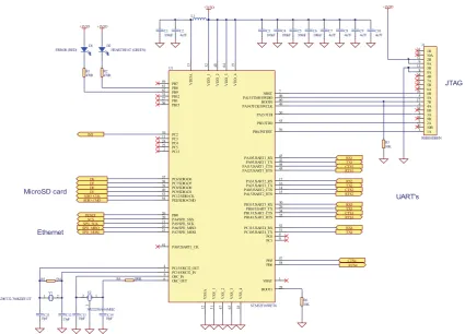
(30) Chapter 3. Hardware design 3.1. Hardware Architecture and Schematic Design. The goal of this chapter is to propose a functional design as stated in Chapter 1. The functional design consists of three parts. First, the Infrastructure has to be developed. The Infrastructure consists of the basic parts, which are power, clock and reset circuits. Second, the logic presentation of each feature has to be determined which meets requirements stated by the sponsor specification. Third, the Medical device connectivity. Serial to Ethernet terminal server is specially designed for the medical environment. The terminal server allows connection of all RS-232 bedside medical devices to the network, sending data to the hospital information system. The features are all parts of the specification stated in Section 1.2. All the electrical connections between peripheral have to be determined. After designing each part of the Infrastructure, the Protel design tool is used for schematic design entry. The following steps are performed with the Altium 6.7 software in order to create a schematic design: 1. Creation of logic symbols for each components. 2. Annotation of all components as a preparation step for the PCB design. 3. Creation of electrical connections between all the components according to component pcbcart manufacturer guidelines. 4. Verification of the schematic design using the Protel Electrical Rule Checker (ERC). The ERC examines the schematic design for both electrical inconsistencies, such as short circuits, e.g., output pins connected to each other, and drafting inconsistencies, such as unconnected net labels or duplicate designators. 17.
(31) Several months of work were dedicated solely to the design of the hardware platform. The process of selecting parts and ensuring the correctness of the final schematics proved to be quite time consuming. The design and schematics went through several iteration before being transformed to a PCB layout.. 3.1.1. Central Processing Unit CPU. The Micro-Controller which has been considered for the design is ARM cortex M3 from STMicroelectronics. This Micro-Controller incorporates the STM32F103RE ARM Thumb 2 processor core, 512KB of flash memory and 64KB of on-chip SRAM, a nested vector interrupt controller, 51 IO lines, 6 times, 4 USART (Universal Synchronous/Asynchronous Receiver/Transmitter) and a 2 watchdog timer. The connection between the peripheral and CPU is shown in Figure 3.1. Figure 3.1: Cortex arch M3. 18.
(32) 3.1.1.1. STM32F103 ARM Cortex M3 Thumb2 Processor. The STM32F103RE processor core is an implementation of the ARM7 architecture. This architecture includes both the 32-bit ARM instruction set and the 16-bit Thumb Instruction set. The 16-bit Thumb instructions duplicate the most commonly used ARM instructions and are used to gain better performance when interfacing with 16 bit wide memory. A three-stage instruction pipeline (fetch, decode, execute) is implemented in the processor core to increase the speed of execution. The STM32F103RE processor core is capable of accessing memory as single bytes (8bits), half words (16-bits) or words (32-bits). An embedded in-circuit emulator is also included for debugging purposes. This can be accessed through a JTAG port. 3.1.1.2. Interrupt Controller. The Interrupt Controller (IC) controls the interrupts generated from the internal peripherals, as well as peripherals connected to the external interrupt lines. One of the external interrupt lines is the Fast Interrupt Line (FIQ). Interrupts occurring on this line have higher priority than all other interrupts. An 8-level priority encoder allows the user to specify the priority of regular interrupts. Internal interrupts can be configured to be level- or edge-triggered, while external interrupts can be configured to be high/low level- or positive/negative edge-triggered interrupts. 3.1.1.3. Timer/Counter. The STM32F32RE includes 6 identical 16-bit timers/counters. These may be used independently, or chained together to create 32- or 48-bit counters. Each counter is capable of generating interrupts via an internal connection to the interrupt controller. The counters may be driven by one of internal clock signals, or one of external clock signals. Each counter also has 2 general-purpose I/O lines that can be used to measure or generate various kinds of waves. Only internal timer functions may be used on the Micro-Controller board, as all external timer I/O pins are used by other devices for I/O. Thus, these pins are programmed in the PIO for external device use.. 19.
(33) 3.1.1.4. USART’s. The STM32F103RE contains 4 Universal Synchronous/Asynchronous Receiver/Transmitters (USARTs) for serial communication. Each USART operates independently, and may be programmed for different speeds, parity, data and stop bits. The baud rate clock of the USART can be generated either from internal clock signals, or an external clock signal. The baud rate clock may only be set from the internal clock signals on the Micro-Controller board, as the external clock pins are used for other I/O devices. Each USART is also capable of generating interrupts via an internal connection to the interrupt controller. 3.1.1.5. On-Chip SRAM. The STM32F103RE incorporates 64KB of on-chip SRAM. This SRAM is internally connected directly to the 32-bit data bus, and allows 32-bit wide single cycle data accesses. 3.1.1.6. Bus Matrix Interface. External memory and peripherals are attached to the CPU via the Bus Matrix. The Bus Matrix has 12 chip selects and a 24-bit address bus with the upper 4 bits of the address bus multiplexed with a chip select. The Micro-Controller board uses a 22-bit address bus. The address bus is controlled by the programmable input output and is used as a chip select. For each chip select, the Bus Matrix allows the user to specify: 1. the data bus width (8 or 16 bits); 2. the number of wait states to be used in accesses; 3. the device page size; 4. the byte access type (byte write or byte select); 5. whether the chip select is active high or active low; and 6. the base address of the device 3.1.1.7. Programmable Input Output PIO. The Programmable Input/output controller (PIO) controls the 51 programmable I/O lines. The 51 I/O lines are multiplexed with signals from the on-chip peripherals. 20.
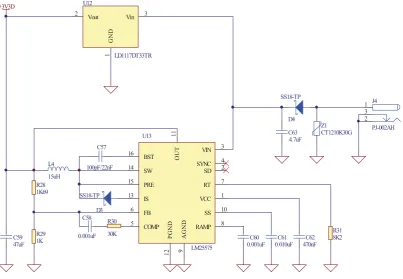
(34) The PIO allows each of the 51 multiplexed lines to be controlled by either the on-chip peripheral or the PIO. All I/O pins are bi-directional, and may be designated as inputs or outputs by the PIO. The PIO also allows each I/O line to generate an interrupt whenever its level changes 3.1.1.8. Watchdog Timer. The watchdog timer is used to reset the system in the event of a software deadlock. The timer is a 16-bit down counter. If the counter reaches 0, the watchdog will generate an internal reset to restart the system.. 3.1.2. Power Supply(Switch Mode). The STM32 requires a single power supply which must be in the range 2.0V to 3.6V. An internal regulator is used to generate a 1.8V supply for the Cortex core. U12. +3V3D. Vout. Vin. 3. 1. GND. 2. LD1117DT33TR. SS18-TP 1 3 2. D4. 15 13. SS18-TP. 6. D3 C58 R29 1K. 0.001uF. 30K. 5. SW. SYNC SD. PRE. RT. IS. VCC. FB COMP. SS. 12. C59 47uF. R30. VIN. AGND. 15uH R28 1K69. 14. 100pF/22nF. PGND. L4. BST. 9. 16. OUT. C57. Z1 CT1210K30G. C63 4.7uF. 11. U13. RAMP LM25575. J4. PJ-002AH. 3 4 2 7 1 10 8 C60 0.001uF. C61 0.010uF. C62 470nF. R31 8K2. Figure 3.2: Switch mode power supply. Power to the main board is supplied by LM25575 a 3.3V regulated switching power supply capable of passing 1.5A of current. A 47uF filtering capacitor is placed on the 3.3V rail, providing filtering and a current reservoir. The PCB uses a 2-layer design with a 21.
(35) ground plane on the solder side in order to reduce noise. The STM32 are powered by the 3.3V rail. The full design of the switch mode power supply is shown in Figure 3.2. 3.1.3. Serial port with optical isolation. The device has a 4 USART controller integrated in the Micro-Controller. The USART can be utilized to send/receive data characters from a peripheral device or modem and converts the data signals between serial and parallel and vice versa. In order to use the UART the following is required: • A component that is able to convert the 3.3V signals originating from the MCU device to RS-232 [20] (+/ - 12V) line voltages and vice versa. This device is also called a line-driver. • The USART interface should include a RJ45 to RS-232 connector cable, which implies to specific connections to the 4 port RJ45 connectors on the board. • The line-driver should support speeds up to 238.400 bit per second which is the maximum rate achievable by the MCU device [40]. In order to support a full RS-232 port on the receiver side (RXD and CTS) and the transmit side (TXD and RTS) signals originating from the Micro-Controller device are connected to a MAX3238CPWR line-driver from Texas Instruments Products [20] Figure 3.3 . The line-driver device supports up to 1Mbit per second which is sufficient for the maximum rate required by the devices. Furthermore a decoupling capacitor is used between the power supply and ground connection for filtering purposes. The opto-isolator is intended to provide electrical isolation between an interface and the equipment connected to its serial port. This required when the system is dealing with completely different voltage levels. Figure 3.3 shows how the electrical isolation is achieved. Connector J2A is linked to the serial port of the device. IC U2 is used to isolate the I/O lines The other side of the isolator carries TTL levels. This side is powered by the target system power supply. IC U2 is used to buffer the signals for the opto-isolator and also drives the data. The interface has been tested at the baud rate of 38.4k baud.. 22.
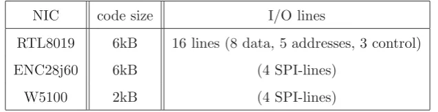
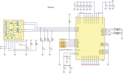
(36) Figure 3.3: Isolated serial port. 3.1.4. Ethernet Controller (Wiznet W5100). There are several Ethernet controllers available in the market. Three Ethernet controllers have been investigated. The first Ethernet Controller is RTL8019, which is NE2000 compatible and was made for ISA-bus usage. This Network Interface Controller (NIC) needs 16 lines for operation, that means almost quarter of the I/O-Ports of an STM32 were taken. Improvements came with the ENC28J60, which has an SPI-Interface and needs only 4 interface lines. Both solutions require a software TCP-IP-Stack which takes about 6kB of program memory. The next step is the W5100 which needs only 1/3 of the code space and supports the SPI-Interface. The following description in Table 3.1 refers only to the SPI-Interface.. NIC. code size. I/O lines. RTL8019. 6kB. 16 lines (8 data, 5 addresses, 3 control). ENC28j60. 6kB. (4 SPI-lines). W5100. 2kB. (4 SPI-lines). Table 3.1: Code space required by different Ethernet controller using SPI interface. 23.
(37) Figure 3.4: Ethernet controller. The Wiznet W5100 was chosen as it provides a very easy to use interface to the Internet. It provides 4 sockets which can be used for any number of network connections. To control the Wiznet module, several interface options are offered: SPI, indirect bus, and a full data/address bus, and also the w5100 is a 3.3V IC with 5V tolerant pins. The SPI bus was chosen since its the simplest implementation as shown in Figure 3.4, the required bandwidth was relatively small, and many Micro-Controllers have SPI peripherals on-board The boot loader support of the STM32 series provides a mechanism for uploading program code by the MCU itself. While the code space for this mechanism is limited, it was not common to upload program code via Ethernet, using the RTL8019 or the ENC28J60. The W5100 hardwired TCP/IP Stack allows bootloader to use Read-While-Write SelfProgramming to the MCU.. 3.1.5. Micro SD Card Storage. The Micro SD card is one of the core parts of this project. Its main purpose is to store all four isolated RS232 channel data into an external storage hence the memory card. This project has been tested with 256 MB Nokia SD memory card. The memory card is connected to CPU thru SDIO (Secure Digital Input output) bus. The following cards sizes are supported by this project are 128MB, 256MB. Figure 3.5 shows the interface to the Micro-Controller. 24.
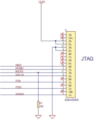
(38) +3V3D. MicroSD card. +3V3D. R26 10K. +3V3D. R27 10K. J11 4 5 6 3 1 2 7 8. SDIO_CLK SDIO_CMD D6 D7 D0 D1. 4 5 6 3 1 2 7 8 DM3AT. Figure 3.5: Implementation of the Micro-SD card. 3.1.6. JTAG. The STM32 MCU has its own on-chip debug system. The Cortex M3, ARM7 and ARM9 CPUs have as a minimum a JTAG port which allows a standard debug tool to connect to the CPU and download code into the internal SRAM or FLASH memory. The JTAG port also have the capability to run basic control (single step and setting breakpoints etc) as well as being able to view the contents of memory locations. The full JTAG implementation is shown in Figure 3.6. Figure 3.6: JTAG interface. For This project, the physical connections for the JTAG interface include 4 wires. 25.
(39) • TCK - Clock. The JTAG clock driven by the MCU • TDI - Data Input driven by the MCU • TMS - JTAG mode input to the MCU • TDO - Data Out. JTAG data output by the MCU 3.1.6.1. JTAG Adapter. JTAG adapter is been designed for the debugging purpose it consists of serial port for the general console debugging and PCI slot for the main board to establishes the connection between the PC and physical hardware. The fallowing Figure 3.7 show the full implementation. Figure 3.7: JTAG adapter interface. of the adapter. 26.
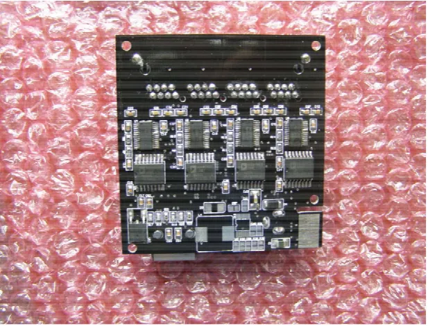
(40) 3.1.7. Final Implementation of the Prototype Boards. Figure 3.8: Top layer of the Final Prototype Board. Figure 3.9: Bottom layer of the Final Prototype Board. 27.
(41) Figure 3.10: Final implementation of the JTAG Adapter. Figure 3.11: Full picture overview of the system. 28.
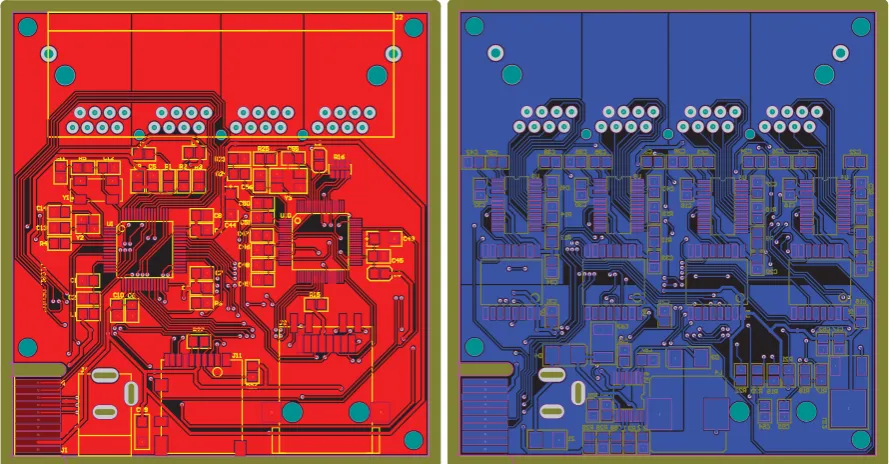
(42) Figure 3.12: Initial design of this project - top layer [4 layer board]. Figure 3.13: Initial design of this project - Bottom layer [4 layer board]. 29.
(43) 3.2. Printed Circuit Board Design (pcb). A Printed Circuit Board (PCB) contains multiple layers stacked on each other with each layer containing a copper pattern. The function of the copper pattern is to provide electrical connections between the components mounted on the PCB. In order to design a PCB a number of steps are needed. First, the PCB Design Rules are extracted from component manufacturer data sheets. PCB Design Rules are indication which the PCB has to comply with in order to guarantee a functional PCB according to specifications. Second, each component requires a footprint, i.e., a mark on the board which consists of lands pads, with correct mechanical dimensions for the component, and solder mask prints. Third, the PCB requires some floorplanning, i.e., the placement of the components on the PCB which apply to the design rules. Finally, trace routing is performed, i.e., the placing of the electrical connections between components in the form of copper traces. During each design-step a Design Rule Verification is performed [29]. The Design Rule Verification compares the PCB layout with the PCB Design Rules in order to detect design errors which need to be corrected. The tool used for the PCB design is the Protel software from Altium [2]. Figure 3.14 shows the PCB layout of the main board and Figure 3.15 shows the JTAG. 37. 35. 38. 33. 36. 34. 2. 2. 31. 27. 32. 1. 1. 23. 21. 26. 24. 1. 1. 1. 1. 1. 2. 2. 2. 2. 2. 1. 2. 25. 28. 2. 2. 17. 22. 18. 15. 16. 13. 11. 14. 7. 12. 1 1. 2. 1. 2. 1. 1. 1. 2. 1 3. 3. 6. 4. 4. 1. 5. 8. 37. 1. 2. 1. 3 2. 1. 1. 2. 2. 2. 2. 27. 32. 2. 1. 28. 3. 1. 1. 2. 1. 25. 26. 23. 21. 24. 17. 22. 2. 1. 18. 2. 1. 1. 15. 13. 16. 2. 1. 2. 2. 1. 3. 1. 2. 3. 2. 1. 14. 11. 7. 12. 5. 8. 3. 6. 1. 4. 2. 2. 1. 2. 1. 2. 1. 1. 2. 1. 2. 2. 1. 2. 1. 2. 1. 2. 1. 1. 2. 2. 1. 2. 2 1. 1. 2. 2. 1 1. 31. 34. 2 1. 1. 33. 36. 2. 1 1. 35. 38. 2. 2. 2. 1. 4. 5. 8. 2. 2. 2. 1. 1. 1. 1. 1. 1. 2 2. 9. 2. 10. 11. 12. 13. 14. 15. 2. 16. 9. 10. 11. 12. 13. 14. 15. 1. 1. 9. 1. 10. 11. 12. 13. 14. 15. 2. 1. 1. 2. 2. 1. 2. 1. 1. 2. 2. 1. 1. 1 1. 2. 2. 16. 2. 2 1. 2. 1. 2. 16. 2 1 2. 1. 2. 2 1. 2. 9. 10. 11. 12. 13. 14. 15. 16. 2. 2. 1. 1. 2. 1. 2. 1 8. 12. 11. 10. 7. 6. 5. 4. 3. 2. 1. 1. 8. 7. 6. 5. 4. 3. 2. 1. 8. 2. 9. 7. 6. 5. 4. 3. 2. 1. 8. 7. 6. 5. 4. 3. 2. 1. 1. 2. 2. 1. 2. 1. 8. 7. 6. 5. 4. 3. 2. 1. 7. 6. 5. 4. 3. 2. 2. 1. 2. 1. 2. 2. 1. 1. 11 12 3. 2. 13. 16. 17 7. 17 18 19. 1. 20. 10 20. 2. 1. 1. 2. 2. 15. 13. 2. 18 8 19 9. 1. 2. 1. 1. 1. 2. 2. 1. 2. 2. 1. 3. 3. 14. 14 4. 16 6. 1. 13. 13 3. 15 5. 2 1. 2. 11 1 12 2. 1. 1. 1 2. 1 8. 1. 2. 2. 1. 2. 2. 1. 2. 2. 2. 2. 2. 1. 1. 1. 1. Figure 3.14: Top and bottom layout of the main board. adapter.. 30. 1. 2. 2. 1. 1. 2.
(44) Figure 3.15: Top and bottom layout of the JTAG adapter. 3.2.1. Overview procedure. A Printed Circuit Board (PCB) is found in almost every electronic device and its purpose is to provide electrical connections between components mounted on it. The electrical connections between the electronic components are implemented with copper traces which carry the signals. Generally there are three types of PCBs: • Single-sided PCB. • Double-sided PCB. • Multi-layer PCB. The single-sided PCB has only through-hole components at one side of the board while traces (and optionally Surface Mount (SMD) components) are routed on the other side of the board. The double-sided board uses both top and bottom side of the board for components and traces. Finally, the multi-layer board is the most complex, it has besides the top and bottom layer, one or more layers embedded between top and bottom side for electrical routing. As PCBs and PCB component sizes decrease continuously, less room is available for copper traces to be placed and thus more layers on a PCB are required [29]. A typical PCB design has to follow the following steps: 31.
(45) 1. Functional design analysis: PCB design rules are extracted from component manufacturer data sheets and PCB guidelines stated in the schematic design. PCB design rules are directives which the PCB has to comply with in order to guarantee a functioning PCB according to specifications. Additional requirements are stated which apply specifically for the PCB, e.g., placing mounting holes. 2. Footprint creation: Each component used must have a PCB footprint, which consists of land pads; solder mask prints, and additionally fiducials. Fiducials are etched features used by the optical system of a pick and place machine as a reference target. The footprint is created according to PCB design rules and component restrictions, e.g., the minimum size of land pads on a footprint. 3. Floorplanning: A floorplanning for the PCB must be performed. Floorplanning is the placement of the components on the PCB which complies with PCB design rules. During floorplanning the layout for power and ground distribution is also considered. Furthermore all additional features must be placed, e.g., placement of PCB mounting holes. 4. Trace routing: After the floorplanning step of the PCB all the connections between the components must be routed. The usual order for routing with high density PCBs is to start with the fan-out routing of all high-density Surface Mount-components, e.g., more than 84 pins in one package. Fan-out routing is routing every land pad out of the footprint. This step is usually done with high- density components in order to be able to connect every component pin. Second is to route all critical traces such as high-frequency and high-voltage signals, because these signals usually have more routing constraints than all remaining signals and thus require maximum flexibility in routing. Finally, the remaining signals are routed. 5. Design rule verification: design rule verification is done during each step of the designflow in order to prevent errors due to PCB design rules. When errors are detected, proper redesign of the PCB is done.. 3.2.2. PCB Design Considerations. In order to specify the PCB requirements the following factors are considered [3]: 1. Trace width and trace clearance requirements: The minimum PCB traces width and clearance on the signal and power and ground plane layers. 32.
(46) 2. Vias: The type of vias on the PCB. 3. Floorplanning: The placement of the components on the PCB. 4. PCB Mask Layer: The use of a protective solder mask and paste mask for assembly. Note that the order different considerations are discussed is from one to four. This is because considerations are dependent on previous decisions, e.g., the type of vias required is among things dependent on the minimal trace width used for dense components. 3.2.2.1. Trace width and trace clearance Requirements. The minimum trace width and trace clearance chosen for the PCB is 5mil in order to provide a maximum possible supply current over the traces. Furthermore most PCB manufacturers require a minimum trace width of 5mil as a manufacturing specification. As a result of this decision the minimum via diameter is 20mil with a hole-size of 10mil. In order to support protection against voltage spikes of up to 1kV a 6mm trace clearance is used for PCB as clearance between low-voltage components and high-voltage traces [29]. 3.2.2.2. Type of vias on the PCB. The PCB board only uses through-hole vias in order to reduce PCB design complexity and cost. In addition all vias and traces can be tested when required. 3.2.2.3. Floorplanning. The routing of all components floorplanning issues must be considered. The following factors are important [29]: • Physical requirements of the PCB • High-voltage signals • Stable power distribution • Heat-dissipating components After analysing the above requirements a floorplan layout is proposed, which is finalized and checked by senior engineer during the implementation stage.. 33.
(47) 3.2.2.4. PCB Mask layer design consideration. The PCB includes an additional 4 mil extra spacing around all the pads in the solder mask layer in case of a slight misalignment. 3.2.3. PCB Implementation. All the footprints for the PCB are created according to PCB design rules and PCB manufacturers recommendations. There are two different types of footprints, standard footprints available from libraries, e.g., 0805 footprint for resistors, and custom footprints which have to be made manually. An example for a custom footprint is the LQFP Ethernet controller footprint. After footprint creation the PCB floorplanning was done. As you can see in Figure 3.16, Figure 3.17, Figure 3.18, and Figure 3.19 this board was the initial design, due to the manufacturing, fabrication and component cost the sponsor has decided to put this design on hold, there for this design has not been fully described in this thesis.. 14 12. 15. 16. 1. 1. 1. 2. 2. 2. 2. 1. 5. 5. 6. 4. 3. 2. 3 3. 1 1. 1. 51. 51. 51. 2. 1. 2. 1. 2. 1. 2. 1. 2. 1. 2. 1. 11. 3. 2. 1. 5. 6. 7. 8. 4. 3. 2. 1. 5. 6. 7. 8. 2. 1. 2 1. 1. 1. 1. 2. 2. 2. 2. 2. 2. 1. 1. 2 2 2. 1. 1. 1. 51. 8. 10. 7. 6. 5. 4. 3. 1. 1. 2. 2. 2. 1. 2. 2. 1. 1. 1. 2. 1. 2. 1. 1 2. 9. 13. 2 1. 1. 2. 2. 2. 1. 1. 1. 8. 1. 2. 3. 4. 1. 2. 7. 6. 1. 2. 1. 2. 3. 5. 6. 7. 8. 2. 5. 1. 2. 1. 2. 1. 2. 2. 2. 1. 1. 1. 4. 2. 1. 1. 2. 2. 2. 1. 2. 1. 1. 8. 2. 7. 3. 6. 4. 5. 1. 2. 2. 2 3 1. 2 1. 2. 2. 2. 1. 1. 1. 2. 1. 1. 2. 3. 2. 1. 15. 14. 16. 13. 15. 6. 19 1. 18. 4. 2. 51. 51. 20. 1. 1. 2. 3. 6. 4. 1. 17. 2. 17. 12. 18. 11. 5. 1. 14. 16. 13. 17. 12. 18. 11. 6. 5 19. 10. 19. 10. 20. 9. 20. 9. 21. 8. 21. 8. 22. 7. 22. 7. 23. 6. 23. 6. 24. 5. 25. 4. 26. 3. 26. 3. 27. 2. 27. 2. 28. 1. 28. 1. 60. 59. 60. 59. 58. 57. 58. 57. 56. 55. 56. 55. 54. 53. 54. 53. 52. 51. 52. 51. 50. 49. 50. 49. 48. 47. 48. 47. 46. 45. 46. 45. 44. 43. 44. 43. 42. 41. 42. 41. 40. 39. 40. 39. 38. 37. 38. 37. 36. 35. 36. 35. 34. 33. 34. 33. 32. 31. 32. 31. 30. 29. 30. 29. 28. 27. 28. 27. 26. 25. 26. 25. 24. 23. 24. 23. 22. 21. 22. 21. 20. 19. 20. 19. 18. 17. 18. 17. 16. 15. 16. 15. 14. 13. 14. 13. 12. 11. 12. 11. 10. 9. 10. 9. 8. 7. 8. 7. 6. 5. 6. 5. 4. 3. 4. 3. 2. 1. 2. 2 1. 16. 2. 3. 4. 15. 14. 13. 12. 11. 10. 9. 8. 7. 3. 3. 1. 2. 4. 2. 2. 1. 1. 1. 5. 15. 14. 15. 3. 16. 13. 17. 12. 18. 11. 19. 10. 20. 9. 21. 8. 21. 8. 22. 7. 22. 7. 23. 6. 23. 6. 24. 5. 24. 5. 25. 4. 25. 4. 6. 3. 5. 16. 13. 17. 12. 1 18. 11. 19. 10. 20. 9. 5. 1. 3. 4. 3. 2. 3. 2 19 1 17. 15. 14. 13. 12. 11. 10. 9. 4. 4. 3. 1. 2. 2. 2. 26. 3. 26. 3. 27. 2. 27. 2. 28. 1. 28. 1. 1. 2. 1. 16. 14. 6. 4. 18. 4. 1. 5. 20. 5. 25. 6. 2. 2. 24. 2. 5 4. 4. 3. 2 1. 2. 6. 4. 1. 1 2. 1. 1 1. 2. 1. 2. 1. 2. 2. 3. 4. 5. 2. 1. 1 1. 1. 1. 2. 6. 7. 5. 1. 2. 1. 1. 2. 2. 2. 1. 2. 1. 2. 2. 2. 2. 2. 1. 1. 1. 1. 3. 1. 2. 1. 1. 1. 1. 2. 2. 2. 2. 1. 1. 1. 1. 1. 2. 2. 1. 2. 1. 2. 2. 1. 1. 2. 1. 2. 2. 1. 2. 2. 2. 2. 2. 4. 6. 2. 2. 2. 2. 1 2. 2. 1. 1. 4. 6. 2. 1. 8. 1. 2. 1. 5. 4. 6. 3. 7. 2. 8. 1. 1. 8. 3 11 2. 12. 13. 14. 15. 23. 1 1. 22 16. 17. 18. 21. 2. 6. 3. 7. 4. 8. 4. 4. 4. 2. 5. 9. 5. 8. 8. 6. 1. 2. 8. 2 8. 20 5. 1. 4. 8. 2. 2. 1. 5. 7 2. 19. 1. 1. 3. 3. 5. 5. 1. 1. 8. 3. 4. 1. Figure 3.16: Top layout of the initial board. 34. 4. 3. 1. 2. 1. 1 2. 1.
Figure
+7

![Figure 3.13: Initial design of this project - Bottom layer [4 layer board]](https://thumb-us.123doks.com/thumbv2/123dok_us/8462001.338462/42.595.155.455.117.343/figure-initial-design-project-layer-layer-board.webp)
Related documents
This conclusion is further supported by the following observations: (i) constitutive expression of stdE and stdF in a Dam + background represses SPI-1 expression (Figure 5); (ii)
19% serve a county. Fourteen per cent of the centers provide service for adjoining states in addition to the states in which they are located; usually these adjoining states have
Хат уу буудай нъ ТгШсит ёигит зүйлд хамаарагддаг нэг настай ихэечлэн зусах хэлбэртэй үет ургамал бөгөөд уураг ихтэй, шилэрхэг үртэй, натур жин их байдгаараа
When the results of the analysis were evaluated according to the Regulation of water pollution of Surface water quality management, the Kızılırmak river was
In earlier days classical inventory model like Harris [1] assumes that the depletion of inventory is due to a constant demand rate. But subsequently, it was noticed that depletion
4b (again, vehicle icons are not drawn to scale). This area was approximately 2. We analyzed scenarios with different vehicle densities per square kilometer, as specified in Table
Also, both diabetic groups there were a positive immunoreactivity of the photoreceptor inner segment, and this was also seen among control ani- mals treated with a
