THE IMPACT OF TRENCHING ON
URBAN ROAD OPERATION AND
MAINTENANCE
LEONG WENG WAH
B ENG
University of Southern Queensland
Faculty of Engineering and Surveying
The Impact of Trenching on Urban Road Operation
and Maintenance
A dissertation submitted by
Leong Weng Wah
in fulfillment of the requirements of
Courses ENG4111 and 4112 Research Project
towards the degree of
Bachelor of Engineering (Civil)
i
ABSTRACT
Trenching works on road pavement is essential with most utility cables being
underground. However, such works often leads to road deterioration due to a number of
reasons. Trenching works on road pavement usually occurs in the road shoulder to
minimize disturbance to traffic.
This project aims to investigate the impact of such trenching works on urban road
operation and maintenance work. Information regarding the impact of trenching, current
standards and Codes of Practice, factors leading to the deterioration of roads after
trenching and current methods used by local councils are researched. A number of sites
around the Klang valley are then investigated and compared with the current standards
available. The advantages and disadvantages of both methods are identified and the best
possible methods are then determined.
From the investigation, it can be concluded that both the standards employed by the
local city council and the usual practice of the contractor have their own advantages.
The standards and guidelines provided by the local city councils are found to be more
effective whereas the usual practice of the sub-contractor is found to be more
economical. Therefore, there should be a closer liaison between the road authority and
utility department’s personnel with the contractor.
ii
University of Southern Queensland
Faculty of Engineering and Surveying
ENG4111 & ENG4112 Research Project
Limitations of Use
The Council of the University of Southern Queensland, its Faculty of Engineering and Surveying, and the staff of the University of Southern Queensland, do not accept any responsibility for the truth, accuracy or completeness of material contained within or associated with this dissertation.
Persons using all or any part of this material do so at their own risk, and not at the risk of the Council of the University of Southern Queensland, its Faculty of Engineering and Surveying or the staff of the University of Southern Queensland.
This dissertation reports an educational exercise and has no purpose or validity beyond this exercise. The sole purpose of the course pair entitled "Research Project" is to contribute to the overall education within the student’s chosen degree program. This document, the associated hardware, software, drawings, and other material set out in the associated appendices should not be used for any other purpose: if they are so used, it is entirely at the risk of the user.
Prof G Baker
Dean
iii
CERTIFICATION OF DISSERTATION
I certify that the ideas, design and experimental work, results, analyses and
conclusions set out in this dissertation are entirely my own effort, except
otherwise indicated and acknowledged.
I further certify that the work is original and has not been previously
submitted for assessment in any other course or institution, except where
specifically stated.
LEONG WENG WAH
0050012473
_______________________________
Signature
_______________________________
iv
ACKNOWLEDGEMENTS
First and foremost I would like to thank my supervisor, Assoc Professor Ron
Ayers, for putting up with me and giving me valuable advices and
recommendations throughout the course of this project. I would not have had
completed this project without his timely adviced.
I would also like to thank my local supervisor, Mr. Ng Kah Chuan who took time
off his hectic schedule to guide and help me in this project.
ZAFAS Pte. Ltd., Inter Region Pte. Ltd., Mentari Murni Pte. Ltd., Persada –
Electrical and Engineering Works Pte. Ltd. and Abadi Ria Pte. Ltd., for providing
the case study for my project and explaining the detail procedures and materials
involved.
Geraldine P. Rozario who helped me made this project a success by introducing
several key people in the government sector.
I am also very grateful to Madeline Chia who actually took time off her holiday to
help me proof read my project.
Last but not least my family and friends for all their continuous support and
encouragement. I am forever indebted to you all.
W.W. Leong
University of Southern Queensland
v
TABLE OF CONTENTS
ABSTRACT
i
DISCLAIMER
ii
CERTIFICATION
iii
ACKNOWLEDGEMENTS
iv
TABLE
OF
CONTENTS
v
LIST
OF
TABLES ix
LIST OF FIGURES
x
CHAPTER
1:
INTRODUCTION 1
1.1 Aims 1
1.2 Objectives 1
1.3 Background of Malaysia 2
1.4 Background of Roads in Malaysia 3
1.4.1 Federal Roads
1.4.2 State Roads
1.5 Roads Administration and Maintenance 6
1.6 Trenching 6
vi
CHAPTER
2:
LITERATURE
REVIEW
9
2.1 Causes of Pavement Deterioration 9
2.2 Types of Maintenance 13
2.2.1 Category 1: Cyclic Maintenance
2.2.2 Category 2: Structural Maintenance
2.2.3 Category 3: Winter Maintenance
2.3 Evaluation of Pavement Performance 18
2.4 Quality control 18
CHAPTER 3:
PROJECT METHODOLOGY
20
3.1 Literature Review 20
3.1.1 Methods Employed 3.1.2 Problem and Difficulties
3.2 Case Studies 22
3.2.1 Methods Employed
3.2.2 Problem and Difficulties
3.3 Comparison of Data and Conclusion 26
CHAPTER 4:
STANDARDS AND CODE OF PRATICE
28
4.1 Guidelines For Relocation of Existing Public Utility 29 Installations and Road Works For Maintenance Repair of
Utility Installations
4.1.1 Work Initiator
4.1.2 Controlling Authority
4.2 Guidelines For Installation of New Utility Service Within 35 Road Reserves
4.2.1 Nature of Work
4.2.2 Work Initiator and Controlling Authority
vii
4.3 Conditions and Specifications of Particular Application 36
4.3.1 General Conditions
4.3.2 Work Specifications
CHAPTER
5:
CASE
STUDIES
42
5.1 Case Study No. 1 – 33 kV Underground Cable (Bangi) 42
5.1.1 General Information
5.1.2 Material Used
5.1.3 Methods Employed
5.2 Case Study No. 2 – Underground Gas Piping (Kajang) 51
5.2.1 General Information
5.2.2 Material Used
5.2.3 Methods Employed
5.3 Case Study No. 3 – 11 kV Underground Cable (Cheras) 62
5.3.1 General Information
5.3.2 Material Used
5.3.3 Methods Employed
5.4 Case Study No. 4 – 33 kV Underground Cable (Serdang) 70
5.4.1 General Information
5.4.2 Material Used
5.4.3 Methods Employed
5.5 Case Study No. 5 – 33 kV Underground Cable (Ampang) 80
5.4.1 General Information
5.4.2 Material Used
5.4.3 Methods Employed
CHAPTER
6:
DISCUSSIONS
92
viii
6.2 Comparisons of Data between Best Possible Methods 101 Employed with the Standards and Code of Practice
CHAPTER
7:
RECOMMENDATIONS 105
CHAPTER
9:
FUTURE
WORKS
107
CHAPTER
9:
CONCLUSIONS
109
LIST
OF
REFERENCES
110
APPENDIX
A
PROJECT
SPECIFICATION 112
APPENDIX B
CASE STUDY QUENTIONNAIRE
115
APPENDIX C
APPLICATION FORM FOR TRENCHING
117
WORK
APPENDIX D
TRAFFIC MANAGEMENT AND SAFETY
128
ROAD
CONSTRUCTION
SITE
APPENDIX
E
PHOTOGRAPHS 163
APPENDIX
F
TECHNICAL
DRAWINGS
168
ix
LIST OF TABLES
Table 1.1: Trenching in Kuala Lumpur for 2003 Table 4.1: Work Categories for Utility Installations Table 4.2: Different Types of Work Initiator
x
LIST OF FIGURES
Figure 1.1: Map of Malaysia Figure 1.2: Road in Malaysia
Figure 1.3: Paved Roads in Malaysia
Figure 1.4: Federal Roads of Every State in Malaysia Figure 1.5: State Roads of Every State in Malaysia
Figure 1.6: Trenching Length (km) in Kuala Lumpur 2003 Figure 2.1: Pavament Deterioration from Trenching Work Figure 2.2: Pothole
Figure 2.3: Reinstated Pavement Without Road Marking Figure 2.4: Laying of |Asphalt After Tack Coat is Applied Figure 5.1: Protective Slab
Figure 5.2: Excavated Material Deposited Beside Open Trench Figure 5.3: Hoes Used Whenever Cables Obstruct
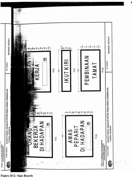
Figure 5.4: Jumping Rammer Compacting the Soil Figure 5.5: Temporary Warning Light and Sign Boards Figure 5.6: Diamond Cutter Cutting the Asphalt Road Figure 5.7: Pipes Clamped Before Welding
Figure 5.8: Joint Pit with Cable Obstruction Figure 5.9: Covered Open Trench
Figure 5.10: Horizontal Directional Drilling (HDD) Figure 5.11: Temporary Sign Boards and Warning Lights Figure 5.12: Orange Protective Plastic Cover
Figure 5.13: Second Layer of Asphalt, First Layer of Asphalt and Existing Road Figure 5.14: Position of Cables Laid
Figure 5.15: Diamond Cutter Cutting in Straight Line Figure 5.16: Quarry Dust Used
xi
Figure 5.18: Water Sprayed to Cool Asphalt Figure 5.19: Installation of Cable
Figure 5.20: Temporary Sign Boards Figure 5.21: Laying of Protective Slabs
Figure 5.22: Obstructing Cable damaged During Excavation Figure 5.23: Joint bay 1
1. INTRODUCTION
1.1Aims
The aims of the project were to investigate the impact of creating trenches in urban roads
for the purpose of cable or drainage system installation. The impacts to be considered
were :-
i) the impact on the operation of the road and surrounding road networks during
the trenching operation;
ii) the impact on the operation of the road following restoration of the trench, and
particularly if failure occurred during the restoration; and
iii) the impact on maintenance operations and budgets caused by defective trench
restorations.
1.2Objectives
The objectives of this project were to :-
i) determine the best practice regarding technique for trenching and pavement
restoration as well as control of trenching operations in roads;
ii) determine techniques and methods used by local city council for trenching and
pavement restoration; and
iii) suggest a better method of trenching and pavement restoration;
1.3 Background of Malaysia
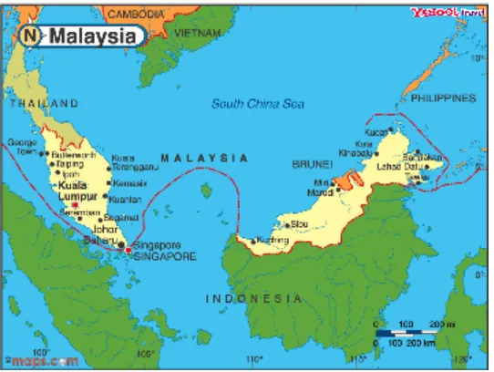
Malaysia is located at South East Asia and is situated to the North West of Australia.
Malaysia comprised of 13 states and a Wilayah Persekutuan (where Kuala Lumpur lies).
Out of the 13 states, only Sabah and Sarawak lies over at the Borneo Island whereas the
[image:15.612.90.361.223.427.2]other 11 states as well as Wilayah Persekutuan lie over at Peninsular Malaysia
Figure 0.1.1: Map of Malaysia
(
http://travel.yahoo.com/p-travelguide-577736-map_of_malaysia-i;_ylt=AiKvfCrEXD7wvIqvP2LoAJNTFWoL)
The state which lies over the west coast of Peninsular Malaysia, mentioned from South to
North, are Johore Darul Takzim, Malacca, Negeri Sembilan Darul Khusus, Selangor
Darul Ehsan, Perak Darul Ridzuan, Penang, Kedah Darul Aman and Perlis Indera
Kayangan. Over at the East Cost of Peninsular Malaysia, mentioned from South to North,
there are Pahang Darul Makmur, Terengganu Darul Iman and Kelantan Darul Naim.
1.4 Background of Roads in Malaysia
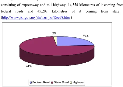
In the year 1993, Malaysia has 60,734 kilometres of roads with 973 kilometres of it
consisting of expressway and toll highway, 14,554 kilometres of it coming from other
federal roads and 45,207 kilometres of it coming from state roads.
(http://www.jkr.gov.my/jln/hari-jkr/Road8.htm )
24%
74%
2%
[image:16.612.87.491.133.419.2]Federal Road State Road Highway
Figure 1.0.2 - Roads in Malaysia
However out of the 60,731 kilometres of roads, 45,273 of the roads are paved. 973
kilometres of the paved roads consist of expressway and toll highway, 13,590 kilometres
of it coming from federal roads and 30,710 kilometres of it coming from state roads.
(http://www.jkr.gov.my/jln/hari-jkr/Road8.htm)
The North-South Expressway, which connects Bukit Kayu Hitam from the North to the
Johor Causeway in the South, is 850 kilometres long. Over at the east coast, there is also
an East-West Expressway. (http://www.abcmalaysia.com/tour_malaysia/trnprt_road.htm)
For safety reasons, the speed limit at these expressways is set to 110 km/hr.
30%
68%
2%
Federal Road State Road Highway
Figure 1.0.3: Paved Roads in Malaysia
Malaysian roads are divided into two main categories :-
i) Federal Roads ii) State Roads
Of the 60,734 kilometres of roads, 24% of it is Federal Roads, and the remaining 74%,
State Roads.
1.4.1 Federal Roads
Federal roads consists of :
i) National Expressways and Highways under the administration of the Malaysian
Highway Authority (MHA)
ii) Highways and roads under the Public Works Department, Malaysia (JKR)
iii) Regional Development Scheme Roads
iv) Federal Land Consolidation Authority (FELCRA) schemes
v) Other Regional Development Authority Scheme and minor roads leading to and
within Federal Government Institutions.
Below is a bar chart showing the federal roads of every state in Malaysia. The federal
road is furthered detailed into pavement federal road, gravel federal road and earth
federal roads.
Figure 1.0.4: Federal Roads of Every State in Malaysia
(http://www.jkr.gov.my/jln/hari-jkr/rdstat.htm)
1.4.2 State Roads
State roads comprise of roads providing intra - state travel between districts, Urban
Collector Roads and other Minor Roads within the villages and the rural inhabited areas.
(http://www.jkr.gov.my/jln/hari-jkr/Road8.htm)
Below is another bar chart showing the state roads of every state in Malaysia. The state
roads is furthered detailed into pavement state road, gravel state road and earth state
roads
Figure 1.0.5: State Roads of Every State in Malaysia
(http://www.jkr.gov.my/jln/hari-jkr/rdstat.htm)
1.5 Roads Administration and Maintenance
Federal roads, apart from those which have been privatised, are funded by the Federal
Government. These funds are allocated by the Public Works Department (JKR) for
administrative and maintenance purposes. The maintenance of State Roads is the
responsibility of the local State Government. However, the Federal Government would
fund the State Government through annual State Road Grants.
1.6 Trenching
Trenches are usually excavated on existing road pavements for cable or drainage
installation. According to dictionary.com, trench is defined as
“A deep furrow or ditch”
while trenching simply means
“To dig a trenches or a trench”
The definition of trench is better defined by Longman Dictionary of Contemporary
English as
“A long narrow hole dug into the surface of the ground”.
Trenching is usually done on the side or shoulder of the road to minimise the disturbance
to traffic flow. However, trenching along the side of the roads is to be avoided if possible.
Trenching is ideal if it can be done on footpaths along the road as this not only minimises
traffic disturbance but also saves cost and time as well.
1.7 Trenching Works in Malaysia
Highways, Federal, State, City and Town Roads have their own designated road
authorities. This will be explained in detailed in Chapter 5 – Standards and Code of
Practice. However, as the site chosen for the case study was situated around the Klang
Valley, this simply meant that the road authorities involved was the Public Works
Department of Malaysia (JKR) who had the authority on State Road and had been given
the authority on Federal Road by the Ministers of Works.
Although all trenching works around the Klang Valley should be submitted to the Kuala
Lumpur JKR, prior notification should be provided to the local City Council of Kuala
Lumpur (Dewan Bandaraya Kuala Lumpur [DBKL]). This enables the local city council
to monitor and answer all enquiries from the public. According to Mr. Khor Keat Hin, a
senior officer at DBKL, there was a total of 102.66 km of cables laid in the year 2003. In
the year 2003, Tenaga National Berhad (TNB), who is also the sole supplier of electricity
in Malaysia, laid a total of 50.785 km of cables, while Telekom, the national
telecommunication company, laid 4.246 km of cables and Perbadanan Urus Air Selangor
(PUAS), the supplier of water in the Klang Valley, laid only 2 km of cables. Other
telecommunication company, such as Maxis, Time Celcom and DIGI laid a total of
45.629 km of cables in that year as well.
Table 1.1 - Trenching in Kuala Lumpur for 2003
Utility Company Length (km)
Tenaga Nasional Berhad (TNB) 50.785
Telekom 4.246
PUAS 2
Others 45.629
0 10 20 30 40 50 60
Others PUAS Telekom TNB
Figure 1.0.6 – Trenching Length (km) in Kuala Lumpur for 2003
2. LITERATURE REVIEW
Normally roads throughout the world deteriorate very slowly and almost imperceptibly in
the first 10-15 years, and then deteriorate much more rapidly unless timely maintenance
is undertaken. It is estimated that $90 billion could be saved, by spending $12 billion on
earlier preventive work. ( Road deterioration and Maintenance Effects, 1987 )
Roads have a design period of 10 – 15 years. Therefore, the deterioration rate of roads
within that time frame is expected to be slow. After 15 years, roads are expected to
deteriorate much more rapidly as the design life of the roads are expected to retire.
Therefore, if maintenance work was undertaken before the roads deteriorates further, the
cost would be much lower compared to the roads which has deteriorated and shows
visible signs of road deficiencies.
2.1 Causes of Pavement Deterioration
There are lots of causes to the deterioration in pavement. Based on “Highway
Engineering” (1987) and “Traffic and Highway Engineering” (1997) a number of causes
to pavement deterioration have been identified. However 10 of the main causes
contributing to pavement deterioration, are :
Figure 2.1: Pavement Deterioration from Trenching Work
i) Weathering/surface water/fuel spillage
These cause embrittlement and failure of the binder, with gradual loss of fine and coarse
aggregate. Frost heave may also occur when water penetrates the sub grade.
ii) Traffic loading
Traffic causes repeated flexing of the pavement leading to fatigue, crazing and structural
failure, especially where the sub grade is weak and distribution of loads are uneven due to
inadequate depth of construction of the carriageway.
iii) Thermal movement
Changes in temperature between night and day and seasonally causes expansion and
contraction of the carriageway, especially where a macadam surface overlies a concrete
foundation. This may progressively cause fatigue and failure at reflective cracks in the
surface.
iv) Moisture movement
Swelling and shrinkage of sub-grades containing clays and silt may occur due to changes
in moisture content. Consequently, reflective cracking and heaving may occur, the extent
of which depends on the type and thickness of construction.
v) Differential movement flexure
This problem occurs at boundaries of different construction which gives rise to adverse
stresses.
vi) Slippage cracking
These are characteristically crescent shaped cracks whose ends are pointing away from
the direction of traffic flow. They form due to friction from braking or turning wheels,
usually in areas of soft, binder-rich surface mix or where a poor bond between the surface
and base course exists.
vii) Reflective joint cracking
This occurs with composite pavement construction. Thermal or moisture induced
movement of a rigid slab foundation causes cracking to develop in the more flexible
surfacing over joints and shrinkage cracks. Spalling, which is fragmentation of the
pavement either side of the crack, may then occur due to fatigue caused by traffic
loading.
viii) Pushing
This term describes the permanent longitudinal displacement of a localised area of the
flexible pavement surface caused by traffic. Normally occurring in soft or binder-rich
surfacing materials, it may also arise where bituminous macadam butts up to a concrete
carriageway and is subjected to differential thermal movement.
ix) Potholes
These are small bowl shaped depressions, usually less than 0.9 meters in diameter, having
sharp edges and vertical sides near the rim. Water collecting inside the hole causes
further deterioration. Potholes usually occur as a result of traffic dislodging small pieces
of surfacing in areas where the binder has become embrittled or subjected to stripping in
the constant presence of water. If not combated effectively early on, the hole may expand
to affect the foundations.
Figure 2.2 : Pothole
x) Rutting
Rutting is the formation of depressions or tracks in the pavement surface caused by wheel
loads and high temperature, depending on the type and design of the carriageway
surfacing.
The loading rate increases with the magnitude of the imposed load, thus at high
temperatures heavy traffic loading is likely to cause rutting. The conditions where the
pavement reaches a temperature above 45 degrees Celsius, or goes above the softening
point of the binder used within the wearing course, causes rutting to accelerate.
Of the 10 causes of pavement deterioration, traffic loading and potholes are the two main
causes of pavement deterioration in trenching works. When a particular road has been
patched up after trenching work has been done, it is expected to settle within 6 months.
During that time, due to constant traffic loading, the roads which had been patched up are
usually settled to a level below the existing road level. Due to rain collecting inside the
hole, stripping occurs and further deteriorates the road
2.2 Types of Maintenance
The frequency and type of maintenance depends upon the severity of the problem.
Therefore there are different categories of road maintenance relating to the type of
problem, each employing different strategies to resolve them.
“Highway Engineering” (1987) and “Traffic and Highway Engineering” (1997) has
categorized road maintenance into three main groups:
i) cyclic maintenance ii) structural maintenance iii) winter maintenance.
The following are brief descriptions of these categories and what they are supposed to
achieve:
2.2.1 Category 1: Cyclic Maintenance
This is general or routine maintenance carried out frequently to aid movement of traffic.
This may involve gully emptying, grass cutting, weed killing, repair to signs and renewal
of markings.
The extent and frequency of these activities depend on the budget allocated by the local
authority based on its own needs.
i) Grass cutting
Rural areas
It is important to keep grass cut where it may inhibit the visibility of drivers i.e. at the
corners of a junction or on the sides of cuttings in a bend in the road. This also stops
encroachment of vegetation on the carriageway and encourages more roots to grow thus
improving the binding of the soil on verges and slopes.
Urban areas
Usually 12 cuts a year is sufficient, which takes place mainly when growth of vegetation
is at its most prolific i.e during the summer season.
ii) Gully maintenance
It is essential to keep the drainage system of carriageways operational. The frequency of
emptying the gullies is dependant on local conditions such as the presence of dirty
industry.
2.2.2 Category 2: Structural Maintenance
Structural maintenance is programmed when required for correcting specific faults
according to an identified need.
i) Patching
This includes repairs to potholes or trench subsidence in carriageways and footways.
ii) Renewal of Traffic Signs
Signs which have been damaged by vandalism or traffic accidents, or are merely too old
should be replaced.
iii) Renewal of Carriageway Markings
Carriageway markings that have been worn away by traffic must be reinstated for the
safety of road users. This activity may be included as part of a Cyclic maintenance
regime.
Figure 2.3: Reinstated Pavement without Road Marking
iv) Surface Dressing
Porous surfaces must be sealed against entry of water, to prevent the onset of further
deterioration or to restore the skidding resistance.
v) Resurfacing of the carriageway
Resurfacing is performed to correct general deterioration of the surface, deformation,
structural failure, surface irregularity, unsatisfactory camber or crossfall.
2.2.3 Category 3: Winter Maintenance
Snow and ice can pose a very serious hazard to vehicles; so it is of great importance to
prevent or remove the effects they can cause the movement of traffic. Due to the
unpredictability of adverse weather, it is necessary to have 24 hour availability of
equipment and crews to clear snow or pre-salt the roads upon receiving weather
warnings.
Three main methods of maintenance are performed:-
i) Salting
Salting should be carried out as a preventative method, but may be done in the early
stages of snowfall. Salting is unviable when the snow becomes hard packed to a depth of
80 mm or more.
ii) Gritting
Gritting is carried out where snow has become hard packed and reduces the slipperiness
of the roads. Single sized 6 to 10 mm material such as crushed stone, sand, grit or cinders
may be used.
iii) Ploughing
Ploughing is employed to remove snow that is hard packed to a depth of 50mm.
Vee-ploughs are suitable for depths of 0.5 to 2.0 meters.
The type of road maintenance which is connected to trenching lies in Category 2:
Structural Maintenance. Trenching for cable installation and drainage along the road
involves the excavation of existing road pavement. Patching, renewal of traffic signs,
renewal of carriageway marking and surface dressing are just some of the maintenance
work involved when trenching is conducted on existing road pavements.
2.3 Evaluation Pavement Performance :-
The evaluation on pavement performance is based on two main criteria, which are :
i) evaluation of pavement surface conditions based on parameters such as
cracking, rutting, surface roughness and skid resistance
ii) evaluation of structural adequacy of pavement
This evaluation is done by testing portions of pavement in isolation or testing an entire
road pavement in non-destructive way. The performance of a typical pavement needs to
be evaluated so that timely measures can be undertaken to ensure and prolong the life
expectancy of a pavement.
2.4 Quality Control
Road performance can be maintained to a satisfactory condition if there is a good quality
control. Quality control of a specific road can be controlled by :-
i) cleaning of existing surface
ii) application of tack coat
iii) laying and rolling temperature
iv) compacting and rolling
(Roadwork Standard:- Tech Report, 1990)
Prior to the application of tack coat, the existing surface needs to be cleaned. This would
mean a smooth even surface. Tack coat is then applied evenly to the surface. The laying
and rolling of asphalt should be of appropriate temperature. Asphalt is then compacted to
ensure that they are settled and smoothly connected to other roads.
Figure 2.4: Laying of Asphalt After Tack Coat is Applied
3. PROJECT METHODOLOGY
After determining the project objectives and aims, the project methodology was
determined. Three main areas which were of significant importance to the project were:- :
1. Literature Review
2. Case studies
3. Comparison of Data and Conclusions
The methods employed, the information gathered and the problems faced for each of
these three areas are described in the following sections.
3.1 Literature Review
The literature review was an important task for the project as it gave a general and
background information regarding roads, their maintenance and other relevant
information. However, before anything was gathered, the type of information and data
needed were first determined. The important information needed were :
i. current methods of traffic control and road network management
during trenching operations
ii. factors leading to the deterioration of roads after trenching operations
iii. current methods used by local councils and other road authorities to
minimise subsequent trench failures
iv. current standards and Codes of Practice controlling trenching
operations and restoration
3.1.1 Methods Employed
After determining the critical information needed, libraries and local city council around
Selangor and Kuala Lumpur were visited. The places visited to gather the information
were :
i) PRIME College - Library
ii) Public Works Department, Malaysia (JKR)
iii) Standard and Industrial Research Institute of Malaysia (SIRIM) – Library
iv) University Putra Malaysia (UPM) – Library
v) Kuala Lumpur International University College (KLIUC) – Library
The medium used to obtain the information needed were through :
1. books
2. magazines
3. journals
4. technical papers
5. the World Wide Web (internet)
Despite having listed the important information needed, other relevant information
closely related to trenching was also gathered. For example : information regarding
trenching, the road systems in Malaysia and general types of road maintenance. As told
by my supervisor in University of Southern Queensland, Prof. Ron Ayers, “It is better to
have more information than less.” This was because with more information, it was just a
process of trimming it down but in the case of less information, one would have the
trouble to gather more.
3.1.2 Problems and Difficulties
Information regarding trenching was hard to find. Therefore to find even more specific
information, such as trenching on road pavement, it was more difficult. Even the internet
failed to provide sufficient relevant information. Search engines such as Yahoo and
Google were able to successfully locate matches when the word ‘trenching’ or ‘trenching
+ road pavement’ or even ‘trenching on road pavement’was typed. There were a long list
of matches found with each of these search engines, however only a few had information
relevant to the project. Books, magazines, journals, and technical papers were not much
help either. Although some of the information proved useful for the introduction chapter,
specific information regarding trenching was hard to obtain.
Standards of the local city council needed to be obtained so that the standard procedures
and material expected from the local city council in a typical trenching work site would
be known. The officers in charge of trenching in the local city council and the Public
Works Department of Malaysia were very co-operative and more than happy to spend
some time from their hectic schedule to provide information. Unfortunately much
detailed information was not given as it was labeled as confidential and therefore
inaccessible.
3.2 Case Studies
The case study is a major element of this project. A number of 3 –5 sites around the
Klang Valley and Kuala Lumpur were chosen as the case study.
The selection of the sites were based on these criteria :
i) the trenching sites must be one which actually cuts through an existing road
pavement;
ii) different contractors should be chosen for each separate case study;
iii) the sites chosen must be one with the approval of the local city council or the
Public Works Department of Malaysia (JKR);
iv) prior notifications should be given to the contractors and the approval of site
visits should be approved; and
v) sites visited should be of a safe nature with minimal life threatening hazard
3.2.1 Methods Employed
i) Locating the trenching site
The Public Work Department (JKR) and the local city council of various districts were
visited, namely :
a. Subang Jaya
b. Petaling Jaya
c. Kajang
d. Kuala Lumpur
There was usually a department, which handled trenching works in each of the local city
council and JKR offices visited. After meeting with the relevant officers in charge,
enquiries were made regarding the possibilities of any ongoing or future trenching works
for drainage or cable installation. The name of the contractor, the company’s name and
their contact numbers were usually given. The contractors were then called and the
possibility of a site visit was determined. If the answer was favourable, the date and time
was then arranged (usually over the night).
All trenching works were done at night except areas near a housing estate. Trenching
works were done at night because traffic flow was at its’ very minimal during the night.
Night works for trenching were prohibited in areas near housing estate because noise
caused from trenching works would disturb the residents staying nearby. The normal
operating hours for a trenching work done at night was from 10.00 p.m. to 6 a.m.
ii) Safety Precaution
Before visiting the trenching site, a list of safety precautions was followed to ensure the
safety of the visitor and others at the site as well. As safety is a very important issue, the
precautions listed below were not taken lightly as site conditions and situations were hard
to predict.
i) Steel capped boots or at least a pair of covered shoe should be worn on site
ii) Hard hats should also be worn at all times
iii) Reflective jackets or bright colored shirt should be worn as most trenching
works in Malaysia was conducted at night
iv) Shirts must be neatly tucked in to avoid from being hooked
v) Listen to the instructions of the site supervisors at all times and do not wander
off without their permission
vi) Photographs should only be taken with the permission of the site supervisor as
the flash from the camera might distract the staff operating the machineries.
iii) Information and Data Collections
The information and data collected at the site were through 2 different mediums:
a) Interview sessions with the site supervisor
b) observations
a) Interview sessions with the site supervisor
The information, which was needed was gathered by interviewing the site supervisor.
General questions regarding the trenching site were asked. Any area of uncertainty or
doubts regarding the trenching site, materials and procedures were also asked during that
time in order to obtain a better understanding.
Listed below were a list of general questions asked to the site supervisors :
i) What is the name of the project?
ii) Who is/are the construction authority?
iii) Who is the main contractor?
iv) Are there any sub-contractors involved? If there are, who are they?
v) When did the construction started?
vi) When is it scheduled to finish?
vii) What is the cost of the project?
viii) What is the average number of workforce in a day?
ix) What major plant item do they use on site?
A standard form similar to the questions above was created to ease the task of data
collection at the site. This helped standardise the questions posed to all site supervisors
and avoided the possibility of forgetting important questions. The form mentioned above
can be found in the Appendix Chapter.
b) Observations
Observing a trenching site was very straight forward. Information which needed to be
recorded were :
i) the materials brought to the site
ii) the step-by-step methods and procedures used by the contractors
iii) problems which arosed at the site and the solutions that were implemented
All information was recorded as detailed as possible. Any enquiries regarding the
materials or procedures used were directed to the project supervisor or the project
engineer (if there were one) on site.
3.2.2 Problems and Difficulties
The only problem faced in this area was locating suitable sites to be considered as a case
studies. The problem did not lie with the local city council or the Public Works
Department of Malaysia, as they were more than willing to provide any assistance. The
few sites which were used as case studies in fact were trenching sites recommended by
them.
According to Mr. Khor Keat Hin , the engineer in charge of trenching in Public Works
Department of Kajang, not all trenching works were done with the knowledge of the
controlling authority. Trenching works submitted to the controlling authority for approval
were those, which were large scale and usually involved more than a days work.
Trenching works done for cable maintenance or a trenching length of only a few meters
were usually not asked for approval. Even if the controlling authority did find out about
the matter, there was not much that could be done as they do not have the authority to
punish them. All that could be done was for them to lodge a report with the police and
wait for the local police to take the necessary action.
Therefore, a suitable trenching site was hard to locate as there were few sites where the
information was sent to the controlling authority for authorization.
3.3 Comparison of Data and Conclusions
After gathering all the information from the case study of various trenching sites, the
information was then compiled. The material as well as the methods and procedures of
each site was then compared. By comparing each and every trenching site investigated,
the best methods for each individual part was then determined.
Having determined the best possible methods and materials from various methods
employed by the contractor, it was then compared with the Codes and Standards of
Practice of the local city council. Both methods were not compared as a whole but
separated into smaller sections and then compared. Based on the results of the
comparison, the conclusions were then determined.
4. STANDARDS AND CODE OF PRACTICE
The standards and code of practice employed by the local city council is written in a book entitled ‘Guidelines For Works Related To Public Utility Installation Within The Road Reserve In Malaysia’
These guidelines have been compiled by the Road Engineering Association of Malaysia
with the aid from a committee in the Maintenance Unit, Roads Branch of the Public
Works Department. The aim of the guidelines is to provide uniform and standard
procedures to control the excavation in roadways so that disruption in road traffic is
minimised and the safety of road users are not compromised.
The problems taken into consideration are :-
i) Disruption to road traffic
ii) Safety for road users
iii) Damage to roads
iv) Damage to utility in or under the roadway
There are basically 3 different guidelines, which are :
a) Relocation of existing public utility and road works for maintenance repair of
utility installations
b) Guidelines for installation of new utility service
c) Conditions and specifications of application
4.1 Guidelines For Relocation of Existing Public Utility Installations and Road Works For Maintenance Repair of Utility Installations
The guidelines are related to the work categorised as follows:-
Table 4.1: Work Categories for Utility Installations
CATEGORY I Relocation of existing utility installation because of road widening or other construction
CATEGORY II Excavation of road for upgrading of existing utility service
CATEGORY III Excavation of road for carrying out maintenance work on existing utility installation
CATEGORY IV Emergency Repair
Emergency Repair – Category IV
In case of emergency repairs such as burst water pipes or cable breakage that need to be
carried out urgently, the relevant utility company may carry out the repair prior to
obtaining approval from the relevant road authority. The utility company however must
carry out the work in accordance with the General Conditions and Work Specifications. It
must also submit an application in the prescribed form together with payment of
necessary fees and guarantee to the road authority within 24 hours of the commencement
of the repair work.
For each of the categories listed above (except for Category IV), 2 parties are involved,
a) Work initiator
b) Controlling authority
4.1.1 Work Initiator
Excavation and relocation works can be initiated by:-
Table 4.2: Different Types Work Initiator
Road Authority For relocation of utility installations
Road Contractor For relocation of utility installations
Developer For relocation or upgrading of utility installations
Utility Company For upgrading or maintenance of utility installations
The work initiator is responsible for :-
i. obtaining the services of a Professional Engineer to prepare engineering
design, worked drawings and specifications for the proposed work
ii. endorsing the plans prepared by the Professional Engineer and submitting to
the relevant controlling authority
iii. paying the prescribed fees and guarantees for the proposed work
iv. carrying out works, upon approval by the controlling authority, according to
the approved plans, specifications and prescribed conditions
4.2.2 Controlling Authority
For all categories of work, there are two controlling authorities which is :-
i) Road Authority
ii) Utility Owner
The Road Authorities consist of :-
i) Minister of Works - for Federal Roads
( who delegates the authority of Public Works Department of Malaysia [ JKR ] )
ii) Director General of Malaysian Highway Authority - for designated highway
iii) Public Works Department of Malaysia [ JKR ] - for State Roads
iv) Mayor - for city roads
v) Municipal Council - for town roads
The Utility Owners comprise of :-
i) Tenaga Nasional Berhad ( TNB )
ii) Telekom Malaysia Berhad
iii) Jabatan Kerja Air
iv) Petronas Gas Berhad
v) Time Telecom Berhad
vi) MAXIS
vii) Etc
Each of these utility owners are empowered to manage the utility installations under the
respective utility act.
The controlling authority is responsible to :-
i. scrutinize the application by the work initiator and approve/disapprove
without undue delay
ii. impose prescribed fees, guarantees and conditions of approval
iii. supervise and monitor the work carried out by the work initiator and enforce
conditions of approval
The inter-relationship among type of work, work initiator and controlling authority is :-
Table 4.3: Relationship between Type of Work, Work Initiator and Controlling Authority
CONTROLLING AUTHORITY CATEGORY TYPE OF
WORK
WORK
INITIATOR FOR ROADS FOR UTILITY
I ( a ) Road authority - Utility owner
I ( b ) Road contractor Road authority Utility owner
I ( c ) Developer Road authority Utility owner
I ( d )
Relocation of
existing utility
installation
Utility owner Road authority -
II
Upgrading or
expansion of
utility service
Utility owner Road authority -
III ( a )
Routine
maintenance of
existing utility
installation
Utility owner Road authority -
III ( b ) Emergency
repair
Utility owner Road authority -
Coordination
With respect to all Categories except for Category IV, the Controlling Authority will
submit a brief report on the proposed work to the “State Coordination Committee for
Public Utility Services ( JKKN )” or the Local Authority Coordination Committee for
Public Utility Services”, whichever is relevant.
Financial responsibility for work
Except for Category I ( c ) of which work relocation of existing utility installation is
initiated by a Developer, the cost of work under all Categories will be borne by the
respective utility company.
Procedures
The following procedures shall apply to works under all Categories except Category
III(b) :-
i) Engineering Design
1. Work Initiator shall appoint a Professional Engineer registered with the Board of
Engineers, Malaysia, under the relevant engineering discipline to carry out the design
of the proposed work.
2. Upon application by the design engineer on behalf of the Work Initiator, the relevant
utility company will cooperate in furnishing to the design engineer’s detailed
information of the existing installations and record of their locations
3. The design drawings of the proposed works shall be in an A1 sized hard copy,
containing sufficient details of the utility installations, their existing location (for
relocation works) and the proposed work location. Locations of the installations must
be accurately surveyed and referenced to local benchmarks and features. The design
engineer shall refer to the Controlling Authority concerned for the format of the
engineering presentation.
4. The proposed work will generally comply with the General Conditions and Work
Specifications as contained in the “Model Application Document”. The design
engineer may, subjected to the approval of the Controlling Authority, modify the
standard specifications or conditions as relevant to the specific work. Such
modifications are to be stated in a page attached to the Model Application Document,
the format of which must be followed.
5. The Application Document will be endorsed by the Work Initiator as well as the
Professional Engineer who makes the design.
ii) Submission & Approval
1. The Work Initiator will make an application to the relevant Controlling Authority
using Borang 1 or Form 1 (please refer to the appendix), attaching two sets of
Application Document for each of the Controlling Authorities. The application forms
will be duly endorsed by the Word Initiator as Applicant, as well as by the design
engineer.
2. Upon receipt of the application, the Controlling Authority shall, within reasonable
time, process and reply to the applicant whether the application has been approved or
requires amendment or re-submission. Borang 2 or Form 2, is a model form of
approval. In Borang 2, the Controlling Authority for road will state the amount of
deposit required for securing proper execution of the works.
3. A Road Work Permit will be issued by the Controlling Authority for road after
receiving the payment of the deposit. Borang 3 or Form 3, is a model form of the
Road Work Permit. No work shall commence without a Road Work Permit.
iii) Work Execution
1. For the relevant part of the design, work must be carried out by suitably qualified
contractors registered with the Construction Industry Development Board, Malaysia
and approved by the Controlling Authority
2. The submitting engineer for the works will supervise the execution of the works by
the contractor to ensure compliance with the design, specifications and approval
conditions
3. When the engineer is satisfied that all work has been satisfactorily completed, he will
submit Borang 4 or Form 4 to the Controlling Authority.
4. If the controlling authority is satisfied with the works after inspection, it will issue a
Certificate of Acceptance of Works as in Borang 5 or Form 5, but withholding the
deposit for a period of six months from the date of the Certificate.
5. Within the six-month period, the applicant will be responsible for repairing any
defects occurring after the Certificate of Acceptance of Works. Upon expiry of the
six-month period and on condition that all defects have been rectified, the Controlling
Authority shall issue Borang 6 or Form 6, whereby the deposit shall be refunded.
4.2 Guidelines For Installation of New Utility Service Within Road Reserves
4.2.1 Nature of work
This part of the Guideline relates to the application by the utility owner for installing new
utility services within the road reserves.
4.2.2 Work Initiator & Controlling Authority
The Work Initiator will be the utility company, which wants to install new utility services
within the road reserve while the Controlling Authority shall be the respective Road
Authority
4.2.3 Procedures
Basically, the procedures and conditions set out in Part 1 of these Guidelines shall apply.
The Work Initiator will submit its proposal as the Applicant, following the said
procedures.
In addition, the Applicant will include an agreement form in the format of Borang 7 or
Form 7 (please refer to appendix) in the Application Document.
4.3 Conditions and Specifications of Particular Application
4.3.1 General Conditions
1. No work shall commence without an official Road Work Permit.
2. All work shall be carried out in accordance with the Specifications contained herein.
3. Unless otherwise approved, all utility installations laid across the road under the
pavement, shall be done by means of trenchless horizontal tunneling technique.
4. A joint site inspection by the Applicant and representative of the Controlling
Authority will be carried out prior to commencement of work to ensure satisfactory
arrangements at site for traffic management and public safety.
5. The Applicant shall at all times keep the site clean and tidy. Approval must be
obtained from the Controlling Authority for storing material and equipment on site.
Upon completion of work, the site will be cleared of all material and equipment and
be reinstated to the satisfaction of the Controlling Authority.
6. The applicant will be responsible for coordinating with other utility companies who
own existing installations in the vicinity of the work to protect their installations and
to avoid disruption to services. The Applicant will comply with the conditions set by
such utility companies.
7. Unless approved otherwise, the Applicant will observe the working hours stated in
the Road Work Permit.
8. There shall be two informational signboards, each measuring at least 2 meters by 2
meters in size, made of approved material and placed at each side of the work site 48
hours prior to the commencement of work. Information on the signboard should
contain brief description of work, commencement and completion dates and the
name, address and telephone number of the Applicant. Location of the signboards
should be approved by the Controlling Authority.
9. Where hydrants are involved, the Applicant should inform the Fire and Rescue
Department in writing seven days prior to the commencement of work, and shall
comply with conditions set by the Department.
10. The Applicant should observe and comply with the regulations of the local authority
pertaining to cutting and removal of trees.
11. The Applicant should be responsible for obtaining permission from private land
owners if the work shall encroach upon private land or access. All existing access
must be kept open to traffic at all times. Temporary diversion approved by the
Controlling Authority shall be provided where necessary.
12. Under no circumstances shall any public road be closed to traffic without the
approval of the Controlling Authority.
13. The Applicant will be liable for damage, loss and claims from third parties for the
damage to public utility installation, private or public property or personal injury or
death from whatsoever that would arise out of or in consequence to the works and
shall indemnify the Controlling Authority against the same.
14. The Applicant should, before commencement of work, submit to the Controlling
Authority a certified true copy of the insurance policy taken in the joint names of the
Applicant and the Controlling Authority.
15. The Applicant should give notice in writing to the Controlling Authority at least 48
hours in advance prior to the commencement of work. Notice should also be given
upon completion of work.
16. Only the contractor or sub-contractor registered with the Construction Industry
Development Board, Malaysia, under the relevant trade group, shall be allowed to
carry out all or any part of the work.
17. The Applicant will be responsible for liaisons with the local Police Department for
traffic control on work site and for the provision of the necessary manpower.
18. At the time of submitting this application, the Applicant will be deemed to have
obtained the approval of the owner of the utility installation to carry out the proposed
work, and shall indemnify the Controlling Authority against claim of damage or
compensation from the owner for whatsoever cause arising out of the work.
4.3.2 Work Specifications
1. The applicant shall submit to the Controlling Authority for approval details of the
system and design of the trenchless excavation across the road. All crossings shall,
unless constrained by site condition, be at right angles to the centerline of the road.
2. Where approval has been granted for open excavation, road pavement at the edges of
the trench must be cut in straight lines by means of a diamond cutter to a depth of at
least 300 mm.
3. No excavated material shall be used for backfilling. All excavated materials must be
removed from the site immediately.
4. Excavated trenches shall be provided with adequate temporary retaining walls or
shuttering to protect against collapse and subsidence or cracking in adjoining
pavement or property.
5. All existing drainage shall be maintained at all times. Temporary diversions, where
unavoidable, may be allowed provided prior approval of the Controlling Authority
has been obtained.
6. Unless otherwise approved, all underground pipes and cables shall be laid with at
least 1000 mm cover measured from the surface of the road, walkway or ground.
7. Prior to the excavation of the trench for laying service installation, the Applicant shall
excavate pilot pits at locations approved by the Controlling Authority in conjunction
with the utility owner to ascertain the exact location of existing service installations.
The number of pilot pits should be sufficient to provide confidence in avoiding
damage to existing installations.
8. The length of trench that can be excavated and left open at any one time shall be
limited to 100 meters. For telecommunication cables, 250 meters may be allowed.
9. Construction materials shall not be stacked on site. Only materials required for the
day’s work shall be brought onto site.
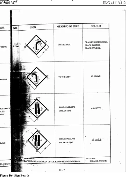
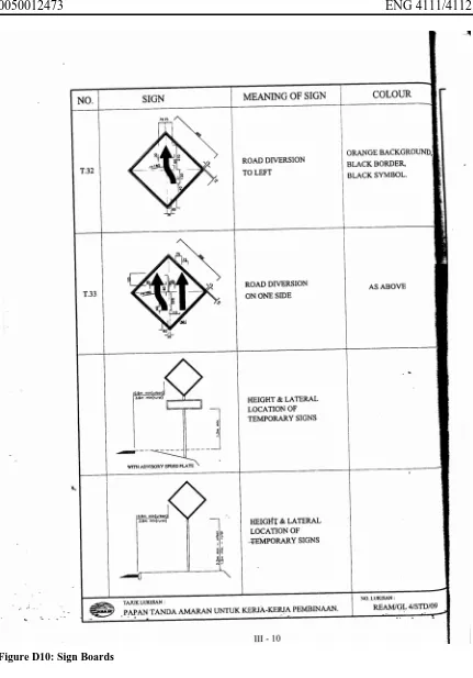
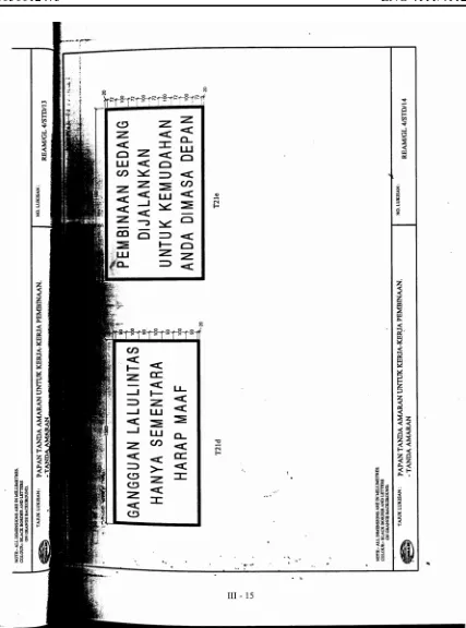
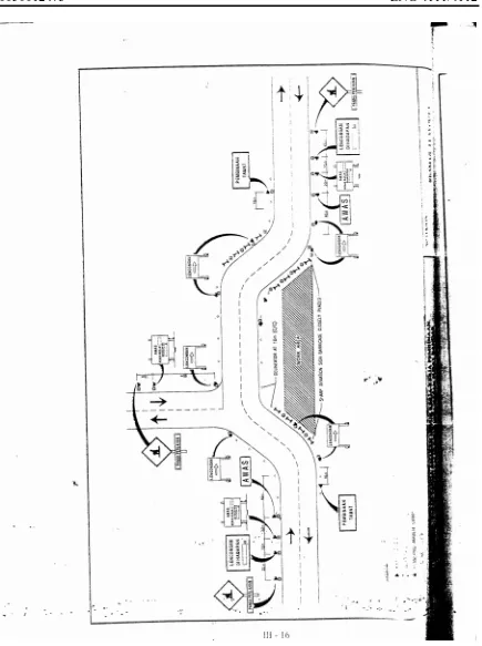
10.The signage for traffic control and management on site shall follow the standard
“Traffic Management and Safety at Road Construction Site” attached in the appendix.
Layout of temporary road diversions, traffic control and location of sign boards
should be in accordance with the traffic management drawings submitted by the
Applicant and approved by the Controlling Authority.
11.Backfilling material for the trench after completion of installation of utility service
shall be granular material of approved grading. Original excavated material from the
trench shall not be used. The backfill material shall be compacted in layers not
exceeding 250 mm with appropriate compactor. The degree of compaction of each
layer below the pavement course shall not be less than 95% of the dry density
obtained using the British Standard heavy Compaction Test. The Controlling
Authority shall have the right to demand re-compaction or removal of backfilled
material if tests reveal that the compaction is below specification. The Applicant shall
bear the costs of re-compaction or removal of backfilled material if tests reveal that
the compaction is below specification. The Applicant shall bear the costs of
re-compaction or removal of backfill material.
12.The controlling Authority reserves the right to carry out tests on the quality of the
material and workmanship any time during the work. The Applicant shall facilitate
the testing and bear all costs thereof.
13.Unless the reinstatement of road pavement is done immediately after backfilling, the
trench shall be temporarily covered with steel plates of suitable thickness securely
spiked to facilitate temporary opening to traffic. Such steel plates shall be maintained
until permanent pavement reinstatement is done.
14.The road pavement shall be reinstated to the same structure as that of the existing
pavement at the least. The Applicant shall submit his proposal (drawings and
specifications) to the Controlling Authority for approval. When in doubt, the
Controlling Authority shall decide on the pavement structure and material
specifications for reinstatement and his decision on this matter shall be final.
15.Pavement reinstatement shall be completed within 3 days after backfilling for
trenches along the road, within 24 hours for cross trenches and immediately for pilot
pits.
16.The reinstated pavement shall be finished flush with the surface of the adjoining
existing pavement.
17.The Applicant shall be liable to carry out repairs to defects in the works at his own
costs for a period of six (6) months from the date of acceptance by the Controlling
Authority.
Try to put in some pictures here. It was very boring because this was like some contract
and the words were very technical. Maybe putting some pictures will help explain some
of the steps.
5. CASE STUDIES
In order to give a clearer picture of a site, the information gathered is separated into three
different categories, which are :-
i) General Information
ii) Materials Used
iii) Methods Employed
5.1 Case Study No. 1 – 33 kV Underground Cable (Bangi)
After interviewing an engineer with the Public Works Department (JKR) of Kajang, Mr.
Lu Kim Hee, on 7th May, the author was informed of an ongoing trenching work in
Section 10, Bandar Baru Bangi. The project involved the installation of 33 kV
underground cables for Tenaga National Berhad (TNB). This project was awarded to
Pembinaan Tajri Sdn. Bhd. A site visit was then arranged with the project manager, Mr.
Hairuddin.
5.1.1 General Information
The case study for this site was conducted on 8th May 2004 at 10.00 p.m. The working
expected to stop by 5.00 a.m. and the contractors were expected to clear up the site and
removed all rubbish and unused material.
According to the contract, the project was entitled ‘Installation and Commissioning of
33kV XLPE Underground Cable for TNB Distribution Network in Selangor – Mainhead
“A”’. The length of the cables was estimated to be 5000 m or 5 km long and would be
from University Kebangsaan Malaysia (UKM) to Section 10 – Bandar Puteri, Bandar
Baru Bangi. Pembinaan Tajri Pte. Ltd. was awarded the right to conduct the project but
had also subcontracted the project to Zafas Pte. Ltd. According to Mr Peter, the project
co-ordinator of ZAFAS Pte. Ltd., the project was tendered in 2002 and work was only
allowed to commence early May 2004.
There were a total of 20 general workers, a project manager, project co-ordinator and
project supervisor, making it a total of 23 employees working for the contractor. On the
day of the site visit, one supervisor as well as one executive officer working for TNB
were also present to check and monitor on the work quality of the contractor.
5.1.2 Materials Used
The materials used at this site were :-
i) fine sand
ii) XLPE power cable
iii) pilot cable
iv) double wall corrugated pipe
v) protective slab
vi) tack coat
vii) asphalt
As for the plant and equipment, there were only five such as:-
i) loader with backhoe attachment
ii) diamond cuter
iii) hand compactor
iv) jumping rammer
v) highway trucks
The length of cables needed to be installed were 5000 m, whereas a drum of cable has
approximately a length of 500 m. This would mean that a minimum total of 10 drums of
cables would be required for each cable. As there were a total of six power cables and
two pilot cables, the amount of drums required were 60 drums of power cables and 20
drums of pilot cables.
One corrugated pipe came in a length of 6 m. By dividing 5000 with 6, we get a total of
833.33. This would mean that a minimum total of 834 corrugated pipes would be
required per cable. A total of 5004 – 150 mm diameter HDPE double wall corrugated
pipe and 1668 number – 100 mm diameter HDPE double wall corrugated pipe was
needed.
Pilot cables consist of optical fibres and copper wires. It is used to detect electronic
signals. Whenever one of the three cables malfunctions, an electronic signal is sent by the
pilot cable. Thus, appropriate actions can be taken to repair or replace the faulty cable.
Maintenance personnel are able to repair the cables underground by getting into the joint
bay which is at a distance of 500 m from one another.
There are 3 different types of XLPE cables which are differentiated by colour – blue,
yellow and red. They are placed at 120º apart. The cables are placed in such a way that
the yellow cables seat on top of the blue and red. The three cables are similar to any
electronic plug where yellow represents earth, red represents life and blue represents
neutral.
5.1.3 Methods Employed
a) General Cable Route
Before the actual trenching work was carried out, the route of the cable was determined.
The excavation of trenching was carried out in accordance with the route indicated in the
route drawing. Corrugated pipes to be laid were ensured to be available before the
excavation started so that laying of pipe could be started as soon as the trench was
completed. The work done had to be organised to ensure minimum time between the
opening of the ground surfaces and final restoration.
b) Supervision of Works
The project manager was responsible for the supervision of work and had a responsibility
to ensure maximum personal safety to personnel directly engaged under the contract as
well as the general public. Similar to any other construction site, a site supervisor was
appointed and supervision work was delegated to them. A project co-ordinator had also
been appointed to ensure sufficient amount of material, plants, machinery and general
workers were available at the site.
c) Breaking of Surface
A diamond cutter was used to cut the sides of the trench sharply in straight lines on
asphaltic road surface. A nozzle located on the diamond cutter sprayed water onto the
road. Water was sprayed to reduce dust particles as the cutter cut the asphalt road and to
ensure the blade of the cutter was always cool. As the blade of the cutter started heating
up, the shape of the cutter tended to change and this would reduce its efficiency. The
width of the trench, cut at the shoulder of the asphalt road was 1300 mm or 1.3 m.
Excavated machine was then used to excavate asphalt road surface as well as soil
underneath the pavement to the desired depth. The excavated machine used at this site
was a loader with a backhoe attachment. A loader with a backhoe attachment was used
instead of a backhoe because the front end bucket enables better support and thus
reducing the need to manoeuvre the plant around. The depth of the trench excavated was
1.2 m deep.
d) Construction of Trenches
Corrugated pipes were ensured to be available before excavation on any section of the
site begun. This ensured that the pipes were ready to be laid when the trench was
completed. The change of level was necessary when there was a variation of depth in the
trenches. The rise and fall of the depth was gradual.
Trenches were kept as straight as possible and the bottom of the trenches were level and
smooth without stones or hard lumps. According to the drawings submitted by
Pembinaan Tajri Pte. Ltd. for approval, the bottom of the trench should be filled with
sand to a thickness of 100 mm to form a bed before cables are laid. However, cables were
actually laid on the bottom of the trench without a layer of sand. After the pipes were
laid, fine sand of approximately 300 mm depth, measured from the top of the corrugated
pipe, were filled into the trench. A protective cover made out of reinforced concrete was
placed atop of the sand. The protective cover functioned as a precaution as well as a
notice indicating an electric cable located 300 mm beneath the cover.
Figure 5.1: Protective cover
Power and pilot cables were laid in the same trench. As specified by TNB, who was the
client, the cables were all laid in corrugated pipes. For power cables, corrugated pipes of
150 mm in diameter were used where as for pilot cables, corrugated pipes of 100 mm in
diameter were used.
e) Excavated Material
Excavated material was deposited neatly beside the open trench. It was placed neatly so
that it caused minimum disturbance to traffic and accessibility to the property. After
backfilling of trench, the surplus material was removed by using a loader with backhoe
attachment to haul the material onto highway trucks. The trucks then off loaded the
surplus material at a suitable place.
Figure 5.2: Excavated Material Deposited Beside Open Trench
f) Obstruction
Whenever the cables or corrugated pipes crossed with any other utility cables, the usage
of mechanical excavating machines, in this case a loader with backhoe attachment was
stopped within one metre on either side of these cables. Instead, hoes were used to
excavate the trench to the required depth. This was one reason why the trenching site