i
University of Southern Queensland
Faculty of Engineering and Surveying
FREQUENCY SYNTHESIZER REQUIREMENTS
FOR FUTURE CELLULAR RADIO SYSTEMS
(06-026)
A dissertation submitted by
Woo Mun Kit
0050014226
in fulfillment of the requirements of
Course ENG4111 and 4112 Research Project
towards the degree of
Bachelor of Engineering (Electrical and Electronics)
ii
ABSTRACT
This dissertation describes the research and experimentation on the future Third Generation (3G) requirements. This project makes used of an integrated Phase Locked Loop (PLL) frequency synthesizer evaluation board from Analog Devices Pte Ltd with an operating frequency range from 2.2 GHz to 2.45 GHz.
The objective of this project is to evaluate the synthesizer requirements of future 3G mobile systems. By extrapolating from existing 3G systems and conducting some researches, it is able to make an educated guess on the frequency synthesizer requirements for the future 3G mobile systems. These requirements and performance are then compared to the hardware evaluation and software simulated findings retrieved from the evaluation board and its simulation software as well as from all other designs. Finally, from the outcome of these comparisons, it is able to conclude which designs are likely to be more suitable for future 3G mobile systems.
Moreover, with this project, apart from giving the student a chance to predict the requirements for future 3G system and verified them in the near future, it also helps to create a good learning experience to any students who are very new to frequency synthesizer system but very much interested in getting to know its performance and how it actually functions.
For the first stage of the project, researches on both the current and future 3G requirements are carried out. At the same time, research on suitable frequency synthesizer techniques and evaluation boards are also conducted. With all the important parameters collected from the researches done for both the current and future 3G requirements, it can then be used as an input criteria in selecting a suitable PLL frequency synthesizer evaluation board from the available market for future 3G applications.
Following the first stage, the second stage will includes hardware evaluation and software simulation on the suitable PLL frequency synthesizer evaluation board bought from Analog Devices Pte Ltd. However, due to some unforeseen circumstances, the hardware evaluation on the evaluation board is unable to carried out smoothly with all the important parameters required for future 3G applications measured as planned, thus another method to retrieve the values of these important parameters has been suggested. The suggested method is to replace the hardware evaluation portion by a software simulation using the simulation software provided by Analog Devices Pte Ltd.
iii
University of Southern Queensland
Faculty of Engineering and Surveying
ENG4111 Research Project Part 1 &
ENG4112 Research Project Part 2
Limitations of Use
The Council of the University of Southern Queensland, its Faculty of Engineering and Surveying, and the staff of the University of Southern Queensland, do not accept any responsibility for the truth, accuracy or completeness of material contained within or associated with this dissertation.
Persons using all or any part of this material do so at their own risk, and not at the risk of the Council of the University of Southern Queensland, its Faculty of Engineering and Surveying or the staff of the University of Southern Queensland.
This dissertation reports an educational exercise and has no purpose or validity beyond this exercise. The sole purpose of the course pair entitled “Research Project” is to contribute to the overall education within the student’s chosen degree program. This document, the associated hardware, software, drawings, and other material set out in the associated appendices should not be used for any other purpose: if they are so used, it is entirely at the risk of the user.
Professor R Smith
Dean
iv
CERTIFICATION
I certify that the ideas, designs and experimental work, results, analyses and conclusions set out in this dissertation are entirely my own effort, except where otherwise indicated and acknowledged.
I further certify that the work is original and has not been previously submitted for assessment in any other course or institution, except where specifically stated.
Woo Mun Kit
Student Number: 0050014226
Signature
v
ACKNOWLEDGEMENTS
First of all, I would like to express my appreciation and gratitude to my supervisor, Associate Professor Jim Ball, for his ideas and guidance he had given to me throughout the duration of this project.
At the same time, I would like to take this opportunity to thank Mr Ian Collins, the Applications Engineer from Analog Devices for taking up the time to answer all my questions on the ADF4360-1 evaluation board and giving me invaluable support. I would also like to thank Ms Ng Kim Ching and Mr Tee Keng Hoe, both colleagues from my workplace for providing me with the access to some of the measuring equipment and allowing me to use their work bench to conduct measurements.
vi
TABLE OF CONTENTS
1. INTRODUCTION ... 1
1.1 Background on Evolution of Cellular Radio ... 1
1.2 Background on Frequency Synthesis... 2
1.3 Project Objectives... 3
1.3.1 Specific Objectives ... 4
1.4 Project Methodology ... 4
1.5 Project Constraints... 6
1.6 Dissertation Overview ... 6
2. BACKGROUND... 8
2.1 Generations of Cellular Radio Systems... 8
2.1.1 First Generation (1G) System ... 8
2.1.2 Second Generation (2G) System... 8
2.1.3 Migration to Third Generation (3G) System... 9
2.2 Present and Future 3G Cellular Radio Systems Standards... 10
2.2.1 Wideband Code Division Multiple Access (WCDMA) ... 14
2.3 Review of Frequency Synthesizer Literature ... 17
2.3.1 Direct Digital Synthesis (DDS)... 17
2.3.2 Phase Locked Loop (PLL) ... 18
2.4 Comparative Analysis on Frequency Synthesizer Evaluation Boards ... 21
3. EVALUATION BOARD... 24
3.1 Description on Evaluation Board... 24
3.2 Capabilities of the Evaluation Board... 27
3.3 ADF4360 Evaluation Board Programmable Software ... 27
3.4 Measurements and Difficulties Encountered... 32
4. SIMULATION SOFTWARE ... 39
4.1 Description on Simulation Software... 39
4.2 Functions of ADIsimPLL ... 39
4.3 Usage of ADIsimPLL ... 46
5. RESULTS... 49
5.1 Results on Hardware Evaluation ... 50
5.2 Results on Software Simulation ... 54
6. DISCUSSION AND CONCLUSIONS... 63
6.1 Results Discussion ... 63
6.2 Conclusion ... 67
6.3 Suggestions for Future Work... 69
vii
8. BIBLIOGRAPHY... 72
9. APPENDICES... 74
9.1 Appendix A – Project Specifications... 74
9.2 Appendix B – Timelines Planning and Work Breakdown Structure (WBS)... 76
9.3 Appendix C – Risk Assessment and Management ... 78
9.3.1 Project Risks ... 78
9.3.2 Safety Issues... 78
9.4 Appendix D – Resource Requirements and Planning... 81
9.5 Appendix E – Articles requesting for higher frequency band below 3 GHz ... 83
9.6 Appendix F – Generated Output Results from ADIsimPLL v.3.0 Software ... 85
9.7 Appendix G – Port Setup Tab from Code Loader v.2.2.0 Software ... 90
9.8 Appendix H – PLL Tab from Code Loader v.2.2.0 Software... 91
9.9 Appendix I – Weekly Progress Report for Wk 637 ... 92
9.10 Appendix J – 1st Measurements on all Test Points in ADF4360-1EB1... 93
viii
LIST OF FIGURES
Figure 1: Methodology Flowchart ... 4
Figure 2: Roadmap from 2G to 3G Systems ... 10
Figure 3: The Five 3G Standards under IMT-2000... 11
Figure 4: WARC-92 IMT-2000 Spectrum Allocation in Europe, USA and Japan. 14 Figure 5: Difference between 2G services using TDMA/CDMA and 3G services using WCDMA ... 15
Figure 6: Basic Block Diagram of a Direct Digital Synthesis (DDS)... 17
Figure 7: Basic Block Diagram of a Phase Locked Loop (PLL)... 18
Figure 8: Picture of the ADF4360-1 Evaluation Board ... 24
Figure 9: Functional Block Diagram of ADF4360-1 Synthesizer IC Chip inside the Evaluation Board ... 25
Figure 10: Main Interface Page of the ADF4360 Evaluation Board Programmable Software ... 28
Figure 11: Screenshot on the Muxout Options menu ... 30
Figure 12: Screenshot on the RF Output Frequency menu ... 31
Figure 13: Screenshot on the Registers menu ... 32
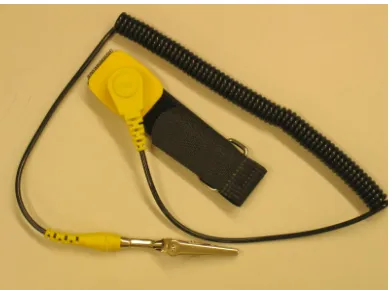
Figure 14: Picture on the ESD Wrist Strap... 33
Figure 15: Picture on the SMA Male Plug to BNC Female Jack Connector ... 34
Figure 16: Picture on the Tektronix TDS3014B High Speed Oscilloscope... 34
Figure 17: Picture on the LeCroy Wave Surfer 424 High Speed Oscilloscope ... 35
Figure 18: Picture on the USB to 25-Pin Female (Parallel) Adaptor Cable... 37
Figure 19: Picture on the Trans PC Card - Universal Parallel Port PCMCIA card ... 37
Figure 20: Screenshot on the Menu for specifying the Frequency Requirements .. 40
Figure 21: Screenshot on the Menu for selecting a PLL IC chip ... 41
ix
Figure 23: Screenshot on the Menu for selecting a VCO ... 43
Figure 24: Screenshot on the Menu for selecting the Reference Frequency ... 44
Figure 25: Screenshot showing the Data Panel and the Results Panel ... 45
Figure 26: Example showing the Usage of the Marker Feature ... 47
Figure 27: Example showing the Usage of the Save Trace Feature ... 47
Figure 28: Test Point T1 Output Waveform using Tektronix TDS3014B ... 50
Figure 29: Test Point T2 Output Waveform using Tektronix TDS3014B ... 50
Figure 30: Test Point T1 Output Waveform using LeCroy Wave Surfer 424 ... 51
Figure 31: Test Point T2 Output Waveform using LeCroy Wave Surfer 424 ... 52
Figure 32: Test Point T3 Output Waveform using LeCroy Wave Surfer 424 ... 53
Figure 33: ADIsimPLL Starting Options for this Project... 54
Figure 34: Absolute Frequency Error Graph ... 56
Figure 35: Output Phase Error Graph ... 56
Figure 36: Total Phase Noise Graph at 2.35 GHz with Loop Bandwidth of 80 KHz ... 60
Figure 37: Frequency Graph with Loop Bandwidth of 80 KHz... 60
x
LIST OF TABLES
Table 1: Advantages and Disadvantages of the 3 Synthesis Techniques ... 3
Table 2: UMTS Frequencies Allocated and Usage for 3G Mobile Systems ... 14
Table 3: 3G Spectrum Usage in Singapore... 16
Table 4: Different Frequency Synthesizer Evaluation Board Comparison Table.. 21
Table 5: Features of ADF4360-1 Evaluation Board ... 27
Table 6: Truth Table for Control Bits C2 and C1 ... 28
Table 7: Phase Noise with Loop Bandwidth of 10 KHz ... 55
Table 8: Phase Noise with Loop Bandwidth of 10 KHz ... 57
Table 9: Frequency and Phase Locking Time with Loop Bandwidth of 10 KHz ... 57
Table 10: Phase Noise with Loop Bandwidth of 790 KHz ... 58
Table 11: Frequency and Phase Locking Time with Loop Bandwidth of 790 KHz58 Table 12: Phase Noise with Loop Bandwidth of 80 KHz ... 59
Table 13: Frequency and Phase Locking Time with Loop Bandwidth of 80 KHz . 59 Table 14: Comparison Table 1 on Requirements between the Synthesizer Design created by ADIsimPLL and the other manufacturer's Frequency Synthesizer Design ... 64
Table 15: Comparison Table 2 on Requirements between the Synthesizer Design created by ADIsimPLL and the other manufacturer's Frequency Synthesizer Design ... 65
Table 16: Comparison Table on Requirements between Synthesizer Design created by ADIsimPLL and the Future 3G predicted Synthesizer Design ... 66
xi
GLOSSARY OF TERMS
3G
Term used to describe mobile systems evolved from the first and second generation of mobile communications networks. 3G systems feature higher data transmission speeds, advanced services and typically make use of new allocations of radio spectrum not available to operators of 2G networks.
3GPP
3GPP basically stands for Third Generation Partnership Project. It is a collaboration agreement that was established in December 1998 whereby this collaboration agreement brings together a number of telecommunications standards bodies that are known as Organizational Partners. The current Organizational Partners are ARIB, CCSA, ETSI, ATIS, TTA, and TTC.
Bell Lab
Known as Bell Laboratories and formerly known as AT&T Bell Laboratories and Bell Telephone Laboratories was the main research and development arm of the United States Bell System.
CDMA
Code Division Multiple Access or CDMA is a form of multiplexing (not a modulation scheme) and a method of multiple access that does not divide up the channel by time (as in TDMA), or frequency (as in FDMA), but instead encodes data with a special code associated with each channel and uses the constructive interference properties of the special codes to perform the multiplexing.
CDMA2000
Code Division Multiple Access 2000 is a family of Third Generation (3G) mobile telecommunications standards that use CDMA, a multiple access scheme for digital radio, to send voice, data, and signalling data (such as a dialed telephone number) between mobile phone and cell sites.
FDD
Frequency division duplex (FDD) is the application of frequency division multiple access to separate outward and return signals. The uplink and downlink sub-bands are said to be separated by the "frequency offset". Frequency division duplex is much more efficient in the case of symmetric traffic. It makes radio planning easier and more efficient since base stations do not "hear" each other (as they transmit and receive in different sub-bands) and therefore will normally not interfere each other.
FDMA
xii
GSA
The Global mobile Suppliers Association, is the forum for, and represents, the leading GSM/3G suppliers world-wide. It is an organization created to meet suppliers’ needs and already represents over 80% of GSM/3G market share globally.
GSM
Second Generation (2G) mobile system originally developed in Europe, using a TDMA access radio interface combined with Frequency Division Multiple Access (FDMA). Oriented to voice and circuit mode data.
HSDPA
Currently being specified by 3GPP as an enhancement to the UMTS Terrestrial Radio Access Network (UTRAN) with the goal of enabling packet data transmission in the downlink at theoretical speeds of up to 10 Mbps.
ITU
International organisation within the United Nations System where governments and the private sector coordinate global telecom networks and services.
PSB Corporation
It is a one-stop integrated solution provider to help you achieve business excellence through people, products and processes. Their Safety Mark Scheme tests and certifies all electrical products for conformity to the Consumer Protection Safety Requirements.
SMA
SMA stand for Sub-Miniature Type-A. SMA connectors provide an economic solution for RF and microwave inter-connection up to 18GHz. It is a dielectrically loaded, sexed connectors for applications where connections are made only a few times, i.e., less than 500 times. The SMA connectors are compatible with 3.5mm and 2.92mm connectors.
Spectrum Analyser
A radio receiver with a swept local oscillator that displays frequency against amplitude on a Cartesian display.
TDMA
Time division multiple access or TDMA is a technology for shared medium, usually radio networks. It allows several users to share the same frequency by dividing it into different timeslots. The users transmit in rapid succession, one after the other, each using his own timeslot. This allows multiple users to share the same transmission medium (e.g. radio frequency) while using only the part of its bandwidth they require.
TD-SCDMA
xiii
and Siemens AG, in an attempt to develop home-grown technology and not be "dependent on Western technology”.
UMTS
3G system standardised by ETSI under 3GPP along with other regional standards organisations.
WARC’92
ITU conference that provided a framework at global level for spectrum to support growth in mobile services towards 3G. Support for non-voice services and international roaming were essential requirements in the brief to identify new spectrum for 3G.
WCDMA
Wideband Code Division Multiple Access is a 3G technology that increases data transmission rates in GSM systems by using the CDMA air interface instead of TDMA. In the ITU's IMT-2000 3G specification, WCDMA has become known as the Direct Sequence (DS) mode.
WiMAX
xiv
Acronyms and Abbreviations
Acronyms Abbreviations
3G Third Generation
3GPP Third Generation Partnership Project
AMPS Advanced Mobile Phone System
ARIB Association of Radio Industries and Businesses ATIS Alliance for Telecommunications Industry Solutions
BNC Bayonet Neill Concellman
CDMA Code Division Multiple Access CDMA2000 Code Division Multiple Access 2000
CE Chip Enabled
CLK Serial Clock Input
CMOS Complementary Metal Oxide Semiconductor
CP Charge Pump
DA Direct Analog
DAC Digital-to-Analog Converter DDS Direct Digital Synthesis
DECT Digital Enhanced Cordless Telecommunications
DS Direct Sequence
DSL Digital Subscriber Line
DSP Digital Signal Processing
EDGE Enhanced Data Rates for Global Evolution ESD Electro Static Discharge
ETSI European Telecommunications Standards Institute FDMA Frequency Division Multiple Access
FDD Frequency Division Duplex
FS Frequency Synthesizer
GUI Graphic User Interface
GPRS General Packet Radio Service
GPS Global Positioning System
GSA Global mobile Suppliers Association GSM Global System for Mobile communications HSDPA High Speed Downlink Packet Access
HSPA High Speed Packet Access
IC Integrated Circuit
iDEN Integrated Digital Enhanced Network IMT International Mobile Telecommunications
I/O Input/Output
IP Internet Protocol
IPv4 Internet Protocol version 4 IPv6 Internet Protocol version 6
ITU International Telecommunications Union
IS-95 Interim Standard 95
IS-136 Interim Standard 136
LE Load Enable
LO Local Oscillator
xv
Acronyms Abbreviations
MC Multi-Carrier
MSB Most Significant Bit
NMT Nordic Mobile Telephone
PC Personal Computer
PCMCIA Personal Computer Memory Card International Association
PDF Phase Detector Frequency
PFD Phase Frequency Detector
PSB Productivity and Standards Board PSTN Public Switched Telephone Network RAMP Risk Assessment and Management Plan
RF Radio Frequency
RTMI Radio Telefono Mobile Integrato
SMA Sub-Miniature Type-A
SMS Short Message Service
TACS Total Access Communication System
TDD Time Division Duplex
TDMA Time Division Multiple Access
TD-SCDMA Time Division-Synchronous Code Division Multiple Access TTC Telecommunication Technology Committee
UMTS Universal Mobile Telecommunications System
USA United States of America
USB Universal Serial Bus
UTRA Universal Terrestrial Radio Access UWC-136 Universal Wireless Communication 136 VCO Voltage Controlled Oscillator
WARC’92 World Administrative Radio Conference 1992
WBS Work Breakdown Structure
WCDMA Wideband Code Division Multiple Access WiMAX World Interoperability for Microwave Access WLAN Wireless Local Area Network
1
1.
INTRODUCTION
This is a project dissertation on the project topic of Frequency Synthesizer Requirements for Future Cellular Radio Systems (06-026). Basically, this dissertation provides some background information on the current Third Generation (3G) mobile radio systems as well as the frequency synthesizer techniques. It also includes a detailed documentation on what are tasks that had been planned to be accomplished as well as how these tasks are being executed in order fulfill the completion of the project. Last but not least, the results collected will be discussed and a conclusion will be made in the last 2 chapters of this project dissertation.
1.1
Background on Evolution of Cellular Radio
Recently the Third Generation (3G) systems had become a very popular topic among all people due to the fact that 3G services had already been adopted in most of the developed countries. The demand for 3G mobile data services is real. Nowadays, not only youngsters but also working adults had been carrying a 3G mobile phone around them. Consumers and business users have consistently demonstrated strong interest in trying new services that combine mobility with content and personalization such as 3G services.
According to UMTS frequencies allocated and usage for 3G mobile systems in Europe and some Asia countries (including Singapore), the operating frequency range for 3G mobile services based on the Frequency Division Duplex (FDD, WCDMA) are 1920 MHz - 1980 MHz for uplink and 2110 MHz - 2170 MHz for downlink. With a channel spacing of 5 MHz, the total bandwidth allocated for 3G mobile WCDMA services is 120 MHz, which will result in having a total number of 24 channels. The frequency range of 1900 MHz – 1920 MHz and 2010 MHz - 2025 MHz are allocated for Time Division Duplex, Time Division/Code Division Multiple Access (TDD, TD/CDMA) uplink and downlink usage while the frequency range of 1980 MHz – 2010 MHz and 2170 MHz - 2200 MHz are for Satellite uplink and downlink used (UMTS Forum, ‘WARC-92 frequencies of IMT-2000’ resolution, 2000).
As of current situation, 3G Wideband Code Division Multiple Access (WCDMA) is the leading mobile 3G system globally with 112 commercial networks in 49 countries. The number of WCDMA subscriptions is estimated to be rapidly approaching 80 million worldwide. Over 50% of WCDMA license holders globally have brought their 3G services to the market. On 8 of August 2006, Global mobile Suppliers Association (GSA) confirms that 44 suppliers have launched 407 3G/WCDMA devices. It means ‘221 new products worldwide came to market in the past 12 months, representing almost 120% growth. The number of WCDMA device suppliers increased from 26 to 44 in the same period’ (GSA, 2006). All of these evidences clearly showed that users have already accepted such new technology and services, which implies 3G evolutions, had finally come.
2
anything till International Telecommunications Union (ITU) finally announces news on future 3G systems. However, with this project, it is able to let the audience to have a feel first on what would future 3G system going to be like and the requirements differences between the current 3G system and the future 3G system.
At the same, this project will provide students a chance to gain forward expertise in one of the most rapidly developing fields within engineering as well as to have the opportunity to gauge what the future 3G systems will be like. With this project in place, it will also helps to create good learning ground to students who have interest in this topic but very new to frequency synthesizer and 3G systems.
All these can be done by the means of investigating the current frequency synthesizers available in the market, evaluate their synthesizer requirements with respect to the requirements for the future 3G mobile systems and finally conclude which frequency synthesizer’s designs are likely to be more suitable for future 3G mobile systems.
1.2
Background on Frequency Synthesis
A frequency synthesizer can be defined as a system that generates one or many frequencies derived from a single time base (reference frequency), in such a way that the ratio of the output to the reference frequency is a rational fraction. There are 3 main conventional techniques being used currently for sine-wave synthesizers and they are all common throughout the industry. One of the most common and popular techniques used in the current Third Generation (3G) mobile system industry is the Phase Locked Loop synthesis or what we normally called as PLL synthesis. Basically, the Phase Locked Loop (PLL) is a feedback mechanism locking its output frequency to a reference.
PLL synthesizers can be found almost everywhere in the communication industry. It can be found in the most sophisticated radar systems or the most demanding satellite communication terminals as well as in our daily household electronic devices such as the car radios and home entertainment stereo systems. The reason why PLL synthesizers are so popular is due to its attractive characteristics of simplicity and economics.
The second technique for sine-wave synthesizer is known as Direct Analog (DA) frequency synthesis. In this technique, a group of reference frequencies is derived from the main reference; and these frequencies are mixed and filtered, added, subtracted or divided according to the required output. However, there will be no feedback mechanisms in the basic technique. Although this technique offers excellent spectral purity and excellent switching speed, however it is usually much more complicated than PLL to execute and hence, when comes to implementation, it tends to be more expensive.
3
like a DDS within the PLL architecture. Nowadays, it is actually quite common to see combinations of PLL and DDS or DA and DDS. From time to time all these 3 techniques are used in one design by designers so as to optimize the design since we all know nowadays an increase in the applications and demands means an increase in the system complexity.
[image:18.612.127.534.239.540.2]In this project, we will focus more on PLL synthesis technique since it is still widely used in the 3G mobile systems and it is much simpler to be implemented for future 3G mobile systems. In addition, the PLL synthesis technique has a very wideband operating frequency, which is more suitable for future 3G applications as compared to DDS since the DDS technique have a limited bandwidth of about 400 to 500 MHz for its operating frequency (Egan, 1990). The tabulated table below highlights the different advantages and disadvantages of these 3 synthesis techniques.
Table 1: Advantages and Disadvantages of the 3 Synthesis Techniques
1.3
Project Objectives
The objective of this project is to evaluate the synthesizer requirements of future 3G mobile systems, which involve a mixture of hardware evaluation and software simulation. By extrapolating from existing 3G systems it will allow the student to make an educated guess at the synthesizer requirements for the future 3G mobile radio systems and compared these requirements and the performance to the actual measured and simulated findings from the frequency synthesizer evaluation board as well as other designs and the simulation software. Finally, conclude which designs are likely to be
Synthesis Techniques
Advantages Disadvantages
Phase Locked Loop (PLL) synthesis
• Simple in design
• Moderate to good switching speeds
• Very wideband operating frequency
• Easy to implement • Low Cost
• Resolution is complicated to achieved
• Good quality oscillators are quite bulky
• Digital modulation is complicated to apply with sufficient accuracy
Direct Analog (DA) synthesis
• Very high switching speeds • Very wideband operating
frequency
• Spectral purity is excellent
• Quite bulky in size since it requires much hardware • Expensive in Cost
• Digital or analog modulation is complicated to apply
Direct Digital Synthesis (DDS)
• Simple and compact • Very high switching speeds • Good resolution very easy to
achieved
• Digital producibility
• Limited bandwidth of about 400 to 500 MHz for operating frequency
4
suitable for 3G and future 3G mobile systems. Specific objectives and the constraints for the project are illustrated in the later sections of this dissertation.
Basically, this project can be broken down into 3 different parts. The first part of the project involves research and investigation on the current 3G and future 3G requirements as well as on the frequency synthesizer evaluation board that are suitable for future 3G applications. The second part will include the evaluation of this suitable frequency synthesizer evaluation board via hardware and simulation software. The last part of this project will consist of comparison of the results or the parameters values collected from the evaluation process with respect to the future 3G requirements and other frequency synthesizer evaluation boards from other manufacturers.
1.3.1 Specific Objectives
The specific objectives or tasks for this project are reflected in the Project Specifications under Appendix A. A Work Breakdown Structure (WBS) and a resource tracking plan based on the Project Specifications, which denotes the planned timelines for major milestones or activities that need to be completed in terms of number of weeks are also attached as Appendix B inside this project dissertation.
1.4
Project Methodology
[image:19.612.133.533.401.681.2]The methodology adopted in this project is based on the timeline with respect to various milestones or objectives defined in order for the completion of the project. This is illustrated in the flowchart shown in Figure 1 below.
Figure 1: Methodology Flowchart
Methodology
Research and Review on required information
Sourcing for available human and non-human resources Planning stage
Measuring and Simulating
Evaluating and Comparing
Recommendation and Conclusion
5
Planning stage is the first and the most important milestone to be accomplished. Without proper planning, the project will not be able to run smoothly and many things such as risks and resources may not be defined or identified beforehand. Planning includes identification of the tasks require to be completed as well as the overall general planning needed to run the project. The completion of the Project Specifications is also considered as part of the planning stage because it defines the way of working together with the specific tasks in the project that need to be completed within the given timelines.
With the basic understanding of the requirements and tasks identified in the Project Specifications, research work started off first by concentrating on information gathering activities, such as researching of current 3G systems as well as reviewing of the frequency synthesizer technologies and carrying out a survey on the current available frequency synthesizer evaluation boards in the market. The main aim for the Research and Review on the required information milestone is to get to know the background knowledge that is essential in order to complete this project successfully. With all the research done and information gathered during the research, it can helps to select a more suitable frequency synthesizer evaluation board that is available in the current market for this project. Furthermore, by doing research on the relevant topics for the project will also helps to provides more information and details in writing the project dissertation.
When all the research is almost completed, a suitable frequency synthesizer evaluation board will be able to be selected for this project use. Before started off to measure the performance of this evaluation board, non-human resources such as the spectrum analyser, oscilloscope and etc needs to be defined and planned. This forms the third milestone on the Sourcing for available human and non-human resources under the methodology flowchart.
After the sourcing of the resources, measuring and simulating of the performance such as the switching time requires for changing channels will be carried out. With all the hardware evaluation measurement findings completed on this evaluation board as well as the simulated findings done using the simulation software, this evaluation board synthesizer design will be evaluated against future requirements for 3G and future 3G systems to see if such design is it suitable for future 3G systems. At the same time, other synthesizer designs will also be evaluated and compared to this evaluation board synthesizer design. The main aim for the Measuring and Simulating as well as the Evaluating and Comparing milestones is to find out the best suitable synthesizer designs for future 3G systems through the experiment and comparison with the requirements collected from all different sources.
6
1.5
Project Constraints
From the start of the project till now, there are a few constraints encountered. They are as follows:
• Not all of the important parameters on the current 3G radio systems are found, only some of these parameters such as the operating frequency range, are being found to use for comparison to the specifications of the evaluation boards available in the market. This is due to the fact that a lot of information on these parameters are not available or clearly specified in places like the library books or the Internet and a lot of this related information such as Third Generation Partnership Project (3GPP) specifications are not easy accessible. Most of the 3G websites (e.g. 3GPP) which has information that are sensitive, requires to be a subscribed member or needs to request for access rights in order to view these information within the site. Another factor is that these parameters are not always standard in values as it will also need to depend on the type of frequency synthesizer the system adopt and other related factors. With this constraint, we can only depend on the few parameters found to look for a suitable frequency synthesizer evaluation board.
• The evaluation board needs to be within the budget allocated of AUD$200, hence with this constraint, it narrow the scope of finding a suitable frequency synthesizer evaluation board available in the market.
1.6
Dissertation Overview
In order to gain a better understanding of the theory of the frequency synthesizer as well as the present and future 3G cellular radio standards that are discussed in this dissertation, some review of the background for these 2 points needs to be made.
Thus, in Chapter 2 of this dissertation, it will first present a summary of the different generations of the Cellular Radio Systems. Then, it will follow up by discussing the present and future 3G Cellular Radio Systems Standards and some background information on the current 3G technology. It will then go on to elaborates on some theory and background knowledge on the WCDMA techniques, which are currently used in 3G mobile services.
The second portion of Chapter 2 will includes a summary of the relevant theory of frequency synthesizer in particular the Phase Locked Loop frequency synthesizer. It will also describe each and every important parameter in a frequency synthesizer that is required for selecting a suitable frequency synthesizer evaluation board for future 3G systems applications. A comparison table between different manufacturers’ frequency synthesizer evaluation board are also illustrated in this chapter. Finally, the project constraints are also illustrated at the end of Chapter 2.
7
includes a short description on the Analog Devices program register software that comes together with the evaluation board. Lastly, it will also discuss on the limitations and difficulties faced during the measuring and evaluating process on the evaluation board.
In Chapter 4, software simulation techniques are discussed here. This will includes some descriptions on the ADIsimPLL simulation software from Analog Devices Pte Ltd, how this simulation software actually works as well as the usage of this simulation software.
In Chapter 5, principally, it presents the results of the measurements conducted on the ADF4360-1 evaluation board itself as well as the results collected from using the ADIsimPLL simulation software. It does not really goes into much discussion on the results collected from both the hardware evaluation and software simulation. The results discussion will be done in Chapter 6 instead.
8
2.
BACKGROUND
To first start with the project, there is need to find out more about the different generation of cellular radio systems, the current 3G mobile radio standards and techniques used, and the plans for future 3G. It is also an essential to understand Phase Locked Loop synthesizers in detail, as there is a need to look for a suitable frequency synthesizer evaluation board for future 3G systems evaluation purposes in this project. Below sections will illustrate more on these few literature review points.
2.1
Generations of Cellular Radio Systems
2.1.1 First Generation (1G) System
In mid 1980’s, the very first hand held mobile phone was commercially launched by one of the mobile phone company named Motorola. This first truly portable hand held phone makes use of the First Generation (1G) mobile communications systems, offering simple wireless voice services based on analog technology. Some of these 1G systems include Nordic Mobile Telephone (NMT), Advanced Mobile Phone System (AMPS), Total Access Communication System (TACS), and Radio Telefono Mobile Integrato (RTMI).
One of the more popular First Generation mobile systems is the AMPS, which is developed by Bell Labs, and officially introduced in United States of America (USA) in 1983 (Wikipedia, Oct 2006). The radio signals used in this AMPS 1G networks are purely analog and the call is not encoded but only modulated to higher frequency (typically 150 MHz and above). In general, 1G systems provide only low quality voice services and were very limited in capacity. Therefore, eventually, 1G systems services did not extend across geographic areas.
2.1.2 Second Generation (2G) System
In the 1990s, the Second Generation (2G) mobile phone systems such as Global System for Mobile communications (GSM), Interim Standard 136 or what we call as IS-136, Integrated Digital Enhanced Network (iDEN) and Interim Standard 95 (IS-95) had been introduced into the market. The digital Second Generation (2G) systems developed in Europe were mainly GSM, based on Time Division Multiple Access (TDMA) technology and in USA mainly IS-95, which is based on Code Division Multiple Access (CDMA) technology.
CDMA technology permits several radios to share the same frequencies. Unlike TDMA, with CDMA, all radios can be active at all the time, because network capacity does not directly limit the number of active radios. Since larger numbers of phones can be served by smaller numbers of cell-sites, CDMA-based standards have a significant economic advantage over TDMA-based standards.
9
new improvements on technologies such as more advanced batteries and more energy-efficient electronics, but also it was largely related to the higher density of cellular sites caused by increasing usage levels based on the higher demands from the subscribers. In 2G networks, they are using digital radio signals rather than analog radio signals. When comparing to 1G systems, the call is encoded to digital signals in 2G systems unlike in 1G systems, the call is only modulated to a higher frequency. Generally, 2G systems provide better voice quality, higher capacity, global roaming capability as well as lower power consumption as compare to 1G systems. 2G systems also offer support for simple non-voice services such as the Short Message Service (SMS) that 1G systems can never provides.
However, there are a few drawbacks of 2G systems. One of it is that, different 2G technologies do not interoperate. There are also difficulties with roaming between GSM and IS-95 countries. In addition to these two drawbacks, the low data rate of 9.6 Kbps provided by the 2G systems (GSM) is not sufficient to meet subscriber demands for new and faster non-voice services on the move. Thus, Third Generation (3G) systems had been created to aim to resolve these problems encountered with 2G systems, by promising global roaming across 3G standards, as well as support for higher data rates and multimedia applications (Holma & Toskala, 2000).
2.1.3 Migration to Third Generation (3G) System
In the evolution from 2G to 3G systems, different migration paths have been identified for GSM-centric and IS-95 or CDMA-centric systems. The objective is to enhance spectral efficiency and network capacity. Mobile operators around the world had migrated their networks either towards 2.5G for General Packet Radio Service (GPRS) or 3G systems directly. Unlike 2G systems, 2.5G and 3G systems will feature packet-switched technology. Packet-switching means that dedicated circuits do not need to be established between communicating devices, and network resources are used only when actual data is transmitted. This means that it is in “always active” connectivity mode for subscribers. The billing for 2.5G and 3G services, are mainly based on either packet-based, time-based or a mixture of the two.
GSM-centric operators have the option to implement General Packet Radio Service (GPRS) and/or Enhanced Data Rates for Global Evolution (EDGE) prior to 3G rollout. GPRS provides a relatively easy upgrade of existing 2G networks to support higher data rates. Commonly considered a 2.5G technology, GPRS offers a theoretical maximum 171.2 Kbps data rate, when all 8 time slots are fully utilised at once. However, it is more likely that subscribers would only be allocated 2 to 4 time slots at one time, thus this will significantly lowered the actual data rate. In addition, initial GPRS deployments would only provide point-to-point support, meaning that subscribers can only communicate with one party at any one time. ‘At present, most of the European operators have already announced commercial GPRS rollouts. GPRS roaming trials had also been conducted in Asia in the last few years’ (GSA, 2006). This means that mobile data services had already been taken off with the advent of higher data rates offered by GPRS.
10
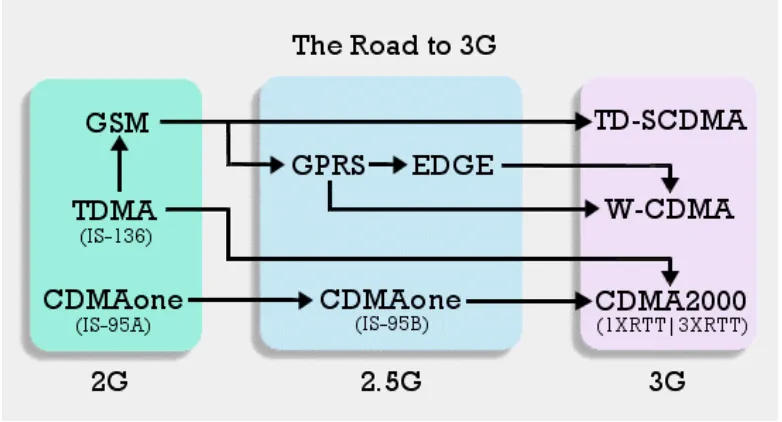
[image:25.612.138.529.328.539.2]offers data rates of up to 384 Kbps through the use of a more efficient modulation technique. Another advantage of EDGE over GPRS is its ability to support for point-to-multipoint communication. Operators without 3G licenses may be able to offer GPRS or EDGE instead. However, some operators may prefer a direct 3G implementation over additional infrastructure costs in association with EDGE. Also, a significant challenge facing GSM migration is handset compatibility. New handsets will be required for every migration step, no matter if it is for GPRS, EDGE, or WCDMA. With the advent of 3G systems, and its accompanying mobile applications and services, mobile devices will become more than just a mobile phone or a basic electronic organiser. Hybrid devices will appear in the near future, supporting not only the traditional voice, but also video streaming and downloads, as well as Internet and intranet access. 3G's high data rate capabilities will allow the convergence of value-added data and voice services on the same mobile device. This will dramatically change the way people communicate, work and carry out their daily lives. Coupled with emerging technologies like Bluetooth, Global Positioning System (GPS) and biometrics authentication, there is enormous possibility for innovative applications to emerge. The diagram below shows a clear roadmap from the Second Generation (2G) mobile systems to 2.5G mobile systems and finally to the Third Generation (3G) mobile systems.
Figure 2: Roadmap from 2G to 3G Systems
2.2
Present and Future 3G Cellular Radio Systems Standards
11
not really standardize on a technology, but rather on a set of requirements (for example, 2 Mbps maximum data rate at indoors, 384 Kbps at outdoors).
IMT-2000 is basically defined from a set of interdependent International Telecommunication Union (ITU) Recommendations. ITU main activities on IMT-2000 consist of international standardisation, which includes the frequency spectrum and technical specifications for radio and network components and etc.
‘The main aim of IMT-2000 is to harmonize worldwide 3G systems to provide global roaming’ (3G Phones, 2006). However, harmonizing so many different standards proved to be extremely difficult. As a result, there are a total of five different standards grouped together under the IMT-2000 label. These five different standards are as follows:
• WCDMA
• CDMA2000
• TD-CDMA/TD-SCDMA • DECT
• UWC-136
[image:26.612.176.491.344.550.2]The diagram shown below illustrates these five 3G standards under IMT-2000 label.
Figure 3: The Five 3G Standards under IMT-2000
12
network"), but it does not allow full network coverage so it is not considered further here. And Universal Wireless Communication 136 (UWC-136), which is another name for EDGE, is generally considered to be a 2.5G solution and it was already considered in the previous section (Kasera & Narang, 2004).
So that leaves WCDMA, CDMA2000, and TD-SCDMA. Out of these three 3G standards, the Wideband CDMA (WCDMA, supported by current GSM-centric countries) and CDMA2000 (supported by current CDMA-centric countries) have emerged as the most prominent contenders. Although both technologies are CDMA-based, major differences exist between them. WCDMA systems work on a RF bandwidth of 5 MHz, much wider than the CDMAone (which is a complete 2G wireless system based on the TIA/EIA IS-95 CDMA standard, including IS-95A and IS-95B revisions) carrier size of 1.25 MHz. The wider bandwidth serves to enhance performance under multipath environments (which means the receiver can better separate the different incoming signals) and increase diversity. Its carriers may be spaced 4.2 MHz to 5.4 MHz apart in an increment of 200 MHz (Kasera & Narang, 2004). The larger spacing is more likely to be applied between operators than within one operator spectrum. This will help to reduce inter-operator interference. WCDMA also offers seamless inter-frequency handover, a useful feature in high-subscriber-density areas.
One major difference between WCDMA and CDMA2000 is that CDMA2000 base stations are network synchronous. In CDMA2000, base stations receive a common reference timing to align their clocks with one another. In CDMA2000, there are two main alternatives for the downlink: Multi-Carrier (MC) or Direct Sequence (DS). The MC approach involves setting up three carrier frequencies, each with a spreading bandwidth of 1.25 MHz. This approach allows co-existence with existing IS95-B systems. In the DS option, only a single carrier is being set up, with a spreading bandwidth of 4.75 MHz. The advantage of DS over MC is better multipath mitigation (Holma & Toskala, 2000).
Another difference between WCDMA and CDMA2000 is the origin. WCDMA is an evolution of GSM, while CDMA2000 is an evolution of CDMA. WCDMA uses a broader spectrum and the signaling is based on GSM. CDMA2000's signaling is somewhat related to TDMA signaling. However on the other hand, both of them use Code Division Multiple Access to get the packets in sequence and both offer similar data speed and voice capabilities.
Whichever the standard that is chosen by an operator, IMT-2000 aims to ensure that in the evolution/migration towards 3G, operators can continue to leverage on existing infrastructure. In addition, all 3G systems will support the following data rates: up to 144 Kbps in macro-cellular environments (e.g. in moving vehicle), up to 384 Kbps in micro-cellular environments (e.g. walking pedestrian) and up to 2 Mbps in indoor/Pico-cellular environments (e.g. in office buildings) (IS224 Project 1, 1999). IMT-2000 has also been designed from the outset to link both terrestrial and satellite components, so that subscribers roaming between terrestrial and satellite networks can expect smooth communication.
13
multimedia services including telephony, paging, messaging, Internet and broadband data transmission. With 3G systems, we are now able to transmit high quality video, images, voices as well as data at a much higher data rate of maximum 2 Mbps to any of our family members, friends or relatives via just a 3G mobile phone. This data transfer rate is definitely much higher as compared to the normal data transfer rate of 9.6 Kbps in the 2G systems (e.g. GSM systems).
One of the Third Generation (3G) mobile systems that were being developed within the IMT-2000 framework is called the Universal Mobile Telecommunications System (UMTS). UMTS is the 3G standard mobile systems that had been agreed for countries such as Europe and Japan. In reality, both Europe and Japan serve as very important markets for 3G systems. At present, UMTS is also being adopted as the 3G standard in Singapore. Basically, UMTS is an upgrade from GSM via GPRS or EDGE. It is the European vision of 3G, and has been sold as the successor to the ultra-successful GSM. The standardisation work for UMTS is being carried-out under the supervision of the Third Generation Partnership Project (3GPP). 3GPP is basically a collaboration agreement that was established in December 1998 whereby this collaboration agreement brings together a number of telecommunications standards bodies that are known as Organizational Partners. The current Organizational Partners are the Association of Radio Industries and Businesses (ARIB), European Telecommunications Standards Institute (ETSI), Alliance for Telecommunications Industry Solutions (ATIS), and Telecommunication Technology Committee (TTC) (Holma & Toskala, 2000).
‘The establishment of 3GPP was formalized in December 1998 by the signing of the Third Generation Partnership Project Agreement’ (Kasera & Narang, 2004). The original scope of 3GPP was to produce globally applicable Technical Specifications and Technical Reports for a Third Generation Mobile System based on evolved GSM core networks and the radio access technologies that they support (i.e., Universal Terrestrial Radio Access (UTRA) both Frequency Division Duplex (FDD) and Time Division Duplex (TDD) modes). Subsequently, this scope was amended to include the maintenance and development of the Global System for Mobile communications (GSM) Technical Specifications and Technical Reports including evolved radio access technologies (e.g. General Packet Radio Service (GPRS) and Enhanced Data rates for GSM Evolution (EDGE)).
The discussions that led to the signing of the 3GPP Agreement were recorded in a series of slides called the Partnership Project Description that describes the basic principles and ideas on which the project is based. The Partnership Project Description has not been maintained since its first creation but the principles of operation of the project still remain valid.
‘The bands 1885-2025 MHz and 2110-2200 MHz are intended for use, on a worldwide basis, by administrations wishing to implement International Mobile Telecommunications-2000 (IMT-2000)’ (UMTS Forum, ‘WARC-92 frequencies of IMT-2000’ resolution, 2000). Such use does not preclude the use of these bands by other services to which they are allocated.
14
Frequency Range Usage
1900-1920 and 2010-2025 MHz
Time Division Duplex (TDD, TD/CDMA) Unpaired. Channel spacing is 5 MHz and raster is 200 KHz. Transmit and receive are not separated in frequency. 1920-1980 and 2110-2170
MHz
Frequency Division Duplex (FDD, WCDMA) Paired uplink and downlink. Channel spacing is 5 MHz and raster is 200 KHz. An Operator needs 3 – 4 channels (2 x 15 MHz or 2 x 20 MHz) to be able to build a high-speed, high-capacity network.
1980-2010 and 2170-2200 MHz
Satellite uplink and downlink usage
Table 2: UMTS Frequencies Allocated and Usage for 3G Mobile Systems
Figure 4 shown below illustrates the WARC-92 IMT-2000 spectrum allocation in countries like Europe, USA and Japan.
Figure 4: WARC-92 IMT-2000 Spectrum Allocation in Europe, USA and Japan
2.2.1 Wideband Code Division Multiple Access (WCDMA)
15
capabilities, increased network capacity and reduced cost for voice and data services. Basically, WCDMA can reach speeds from 384 Kbps to 2 Mbps, which represents from 6 to 35 times more than what regular landline modems can do. At that speed, wideband services such as streaming video and video-conference is achievable.
The implementation of WCDMA will be a technical challenge because of its complexity and versatility. The complexity of WCDMA systems can be viewed from different angles: the complexity of each single algorithm, the complexity of the overall system and the computational complexity of a receiver. WCDMA link-level simulations are over 10 times more compute-intensive than current Second Generation (2G) simulations. In WCDMA interface, different users can simultaneously transmit at different data rates and data rates can even vary in time. UMTS networks need to support all current Second Generation (2G) services and numerous new applications and services (Kasera & Narang, 2004).
[image:30.612.226.424.298.416.2]The diagram shown below illustrates the difference between 2G services using TDMA or CDMA technologies and the 3G services using WCDMA technology.
Figure 5: Difference between 2G services using TDMA/CDMA and 3G services using WCDMA
At present, all the 3 service operators (SingTel, Mobile One (M1) and StarHub) in Singapore are having operational 3G coverage all over the island for almost 1 year already.
16
Paired 3G
Spectrum Operator Lower Band Upper Band Unpaired
Type of Services Used
A StarHub 1920 - 1935.1 MHz
2110.3 - 2125.1 MHz
1914.9 - 1920
MHZ WCDMA
B SingTel 1935.1 - 1950.1 MHZ
2125.1 - 2140.1 MHz
1909.9 - 1914.9
MHz WCDMA
C M1 1950.1 - 1964.9 MHz
2140.1 - 2154.9 MHz
1904.9 - 1909.9
MHz WCDMA
D - 1964.9 - 1979.7
MHz
2154.9 - 2169.7 MHz
1899.9 - 1904.9
MHz -
Note: The frequency list is a range.
Table 3: 3G Spectrum Usage in Singapore
At this point of time, SingTel and other mobile service operators are only looking into World Interoperability for Microwave Access (WiMax) and High Speed Downlink Packet Access (HSDPA) that can be consider as the 3.5G portion. There is still no indication of going into the Fourth Generation (4G) system yet. HSDPA can be consider, as the upgrade version of the current 3G WCDMA, and it is a global standard technology enabling video conferencing with high data speed as well as capacity abilities for the users. Apart from providing high-speed downlink data capabilities to WCDMA (UMTS) networks, HSDPA also allows wireless users to stream high-quality video and audio, quickly browse graphics-heavy websites, and run other advanced applications on mobile handsets. HSDPA is an evolution of existing WCDMA networks that provides a powerful boost in data rates and an increase in overall network capacity. Theoretically, HSDPA technology can provides up to a maximum download speed of 14.4 Mbps (GSM World, 2006).
Now, the question is, “What will be fate of 3G systems in 2 to 3 years down the road?” “What will be the future 3G systems going to be like?” “Will there be 4G systems coming up soon to replace the current 3G systems?” Nobody really knows. However, from the current direction that 3G systems are going through, it is possible to predict what will the future 3G systems going to be like.
From reading of some articles in the UMTS forum and Third Generation Partnership Project (3GPP) websites, there is a demand for a higher frequency band for future 3G systems. The range indicated for this higher frequency band normally falls within the range from 2.3 GHz to 3 GHz (UMTS Forum, 2003). Appendix E shows some other articles in requesting a need for a higher frequency band from 2.5 GHz to 2.69 GHz and below 3 GHz.
17
what will 4G be like since currently there are no much information on that. Therefore, as per now, the operating frequency band for future 3G Services can be predicted to be within the range from 2.3 GHz onwards to 3 GHz. For this project, in a more conventional way, the operating frequency range had been chosen to be around 2.3 to 2.5 GHz. It is not necessary to go as high as 2.5 GHz operating frequency since the current maximum operating frequency for 3G systems is only 2.2 GHz.
2.3
Review of Frequency Synthesizer Literature
Basically, frequency synthesizers form the basis of most radio system designs and their performance is often the key to the overall operation. A frequency synthesizer mainly generates many frequencies derived from a reference frequency. The output frequency divided by the reference frequency will give a rational fraction. This output frequency can be either directly or indirectly related to the reference frequency and with this, it leads to 2 main types of frequency synthesizer. They are the direct and the indirect frequency synthesizer.
As mentioned in Chapter 1, there are mainly 3 frequency synthesizer techniques being used commonly in the industry. They are the Phase Locked Loop (PLL) synthesis, the Direct Analog (DA) frequency synthesis and the Direct Digital Synthesis (DDS). As DA frequency synthesis is becoming less popular among engineers in the industry due to its complicated and expensive analog techniques used, hence only DDS and PLL will be discussed further in details in the following sections.
2.3.1 Direct Digital Synthesis (DDS)
Direct Digital Synthesis (DDS) is actually used in a direct frequency synthesizer. For a direct frequency synthesizer, it will produce an output, which is directly proportional to the input. DDS uses Digital Signal Processing (DSP) circuitry and techniques to create, manipulate, and modulate a signal digitally and finally convert this digital signal into its analog form by using a Digital-to-Analog Converter (DAC) (Egan, 1990).
Below reflects the basic block diagram of a Direct Digital Synthesis (DDS).
18
Since, the DDS is limited by the bandwidth of 400 MHz to 500 MHz for operating frequency and for 3G and future 3G applications, it needs a wide bandwidth operating frequency up to about 3 GHz, hence PLL is more suitable for such applications as compare to DDS. Therefore, PLL is eventually chosen to be the synthesizer technique for this project.
2.3.2 Phase Locked Loop (PLL)
Phase Locked Loop (PLL) is used in an indirect frequency synthesizer. It is a feedback mechanism locking its output frequency to a reference.
In real life, PLL synthesizers can be found almost everywhere in the communication industry. As mentioned in the earlier section, the Phase Locked loop (PLL) is by far the most popular frequency synthesis technique all because of its simple, economic and a very wideband operating frequency characteristics. It is basically a non-linear (the phase detector is a non-linear device) feedback loop, as shown in the Figure 7 in the following page.
Note: The shaded area is usually integrated into a synthesizer IC chip.
Figure 7: Basic Block Diagram of a Phase Locked Loop (PLL)
Normally, the PLL will consist of a voltage controlled oscillator (VCO), a phase detector, a variety of dividers, and a loop filter. The VCO is a device whose output frequency depends on the input control voltage. The relation is non-linear but monotonic. However, when locked, the VCO can be assumed to be linear; it is both practical and convenient for analytical purposes. Variation in the VCO control characteristics (e.g. this nonlinearity) affects the loop parameters, and loop linearization or compensation is used extensively (Curtin & O'Brien, 1999).
With respect to the basic block diagram of the Phase Locked Loop (PLL) shown above, the VCO output frequency, Fout is ‘Locked’ to the reference frequency, Fref when this
reference frequency, Fref is being divided by some integer R, the VCO output frequency,
Fout is divided by some integer N, and then compare the phase of these 2 signals to
generate an error signal. This error signal is then amplified and filtered to remove phase comparison frequency components as well as to provide closed loop stability. It is
Z(s)
÷ N
VCO
F
outPhase Detector
F
ref÷ R
Kphi
Loop Filter
19
almost always the case that the reference frequency, Fref is a higher quality frequency
source than the VCO output frequency, Fout.
Like any other engineering product, a frequency synthesizer (FS) needs to meet a set of specifications or parameters. A list of major synthesizer parameters that are important to this project are illustrated as below (Egan, 1990).
Frequency Range
This specifies the output frequency range, including the lower and higher frequencies that can be obtained from the frequency synthesizer. The units of frequency are hertz (Hz), or cycles per second.
Frequency Resolution
This parameter is also referred to as the step size, and it specifies the minimum step size of the frequency increments. For example, if a frequency synthesizer covers a frequency range from 1.5 GHz to 3 GHz and has a step size of 100 Hz; it is capable of generating any frequency between 1.5 GHz to 3 GHz in 100 Hz steps. In many applications, the step size is not fixed. This happens when a part of the synthesizer is generated by dividing a fixed frequency with a range of numbers.
Channel Spacing
This specifies the amount of bandwidth allocated to each channel in a communications system that transmits multiple frequencies such as the frequency synthesizer. It is measured as the spacing between center frequencies (or wavelengths) of adjacent channels.
Phase Noise at a Specific Offset from the Output
For a carrier frequency at a given power level, the phase noise of a synthesizer is the ratio of the carrier power to the power found in a 1-Hz bandwidth at a defined frequency offset (usually 1 KHz for a synthesizer). Expressed in dBc/Hz, the in-band (or close-in) phase noise is dominated by the synthesizer; the VCO noise contribution is high-pass filtered in the closed loop.
Acquisition/Lock Time after Switching to a New Frequency (to get within one cycle slip of new frequency)
This refers to the period of time required to attain synchronism in the frequency synthesizer especially after switching from one specified frequency to another new frequency in order to get within one cycle slip of new frequency.
Settling/Lock Time (for phase error to decrease from near 360 degrees to near zero)
20
required for a signal to reach certain accuracy and stay within that range of accuracy. Settling time can be a major source of error for multichannel acquisition systems because the switching between channels can cause large voltage steps that the instrumentation amplifier may not be able to track quickly.
Switching Time
This parameter specifies the speed whereby the frequency synthesizer can hop from one specified frequency to another specified frequency within a given frequency tolerance. There are many definitions for this parameter. In some applications, the requirement is to settle to within a specific frequency from the desired new frequency (e.g. 10 Hz or 1 KHz from the desired frequency). Another more common but more demanding specification that defines the switching speed is by the time it takes the output phase to settle to 0.1 radian of the final phase.
Spurious Signal Level
Overmodulation on the signal will results in spurious signal created and the level of such unwanted spurious signal is called the spurious signal level. Active RF and microwave systems frequently generate non-harmonically related signals that need to be identified and measured. Tracking down and then reducing the level of unwanted spurious signals can be done by using a spectrum analyser.
Power Consumption/Dissipation
This refers to the electrical energy over time that must be supplied to the frequency synthesizer so as to maintain its operation. The power consumption is usually a result of power used to perform the intended function of the device plus additional "wasted" power that is dissipated as heat and/or light. On the other hand, power dissipation is the transference of heat generated by the device during normal operation. Both the power consumption and power dissipation is usually measured in units of watts.
First of all, in order to look for a suitable frequency synthesizer evaluation board for measurement and comparison to current 3G and predicted future 3G synthesizer design, there is a need to search for all those important parameters of the current 3G radio system that are mentioned above. Unfortunately, not all of these important parameters on the current 3G radio systems are found. Only some of the typical values of these parameters that are being used currently in 3G systems are found to compare to the specifications of the evaluation boards available in the market. A survey on the available frequency synthesizer evaluation boards from different manufacturers such as Analog Devices, National Semiconductor, Texas Instruments and etc is also being conducted in the starting phase of this project. Having the constraints of the budget allocated as well as the suitable 3G specifications required, there are only a total of 6 potential frequency synthesizer evaluation boards that are available and suitable for this project.
21
2.4
Comparative Analysis on Frequency Synthesizer Evaluation Boards
For comparative analysis on these 6 different frequency synthesizer evaluation boards available in the market, a comparison table had been drawn up as shown below.
Table 4: Different Frequency Synthesizer Evaluation Board Comparison Table
Manufacturer Analog Devices National Semiconductor Texas Instrument
Singapore Technologies Model No ADF4360-1 ADF4360-0 LMX2310U LMX2347 TRF3761 STW81100 Price US$120 US$120 US$147 US$147 Not Indicated Not Indicated
Integrated VCO Yes Yes No No Yes Yes
Operating Frequency Range
2.05 GHz to 2.45 GHz
2.4 GHz to
2.725 GHz 2.5 GHz 2.5 GHz
375 MHz to 2.4 GHz
825 MHz to 4.4 GHz
Data to Clock Set
Up Time 10 ns (Min) 10 ns (Min) 50 ns (Min) 50 ns (Min) 10 ns (Min) 2 ns (Min) Data to Clock
Hold Time 10 ns (Min) 10 ns (Min) 20 ns (Min) 10 ns (Min) 10 ns (Min) 2 ns (Min) Clock Pulse
Width High 25 ns (Min) 25 ns (Min) 50 ns (Min) 50 ns (Min) 50 ns (Min) 10 ns (Min) Clock Pulse
Width Low 25 ns (Min) 25 ns (Min) 50 ns (Min) 50 ns (Min) 50 ns (Min) 5 ns (Min) Lock Time/
Switching Time 400 µs (Typ) 250 µs (Typ) 500 µs (Typ) 450 µs (Typ) 300 µs (Typ) 150 µs (Typ)
VCO Phase-Noise Performance
-148 dBc/Hz (Typ) at 10 MHz
offset from carrier
-145 dBc/Hz (Typ) at 10 MHz
offset from carrier
N.A. N.A.
-160 dBc/Hz (Typ) at 10 MHz
offset from carrier
-148 dBc/Hz (Typ) at 10 MHz
offset from carrier
In-Band Phase Noise
-81 dBc/Hz (Typ) at 1 KHz
offset from carrier
-80 dBc/Hz (Typ) at 1 KHz
offset from carrier
-76 dBc/Hz (Typ) at 1 KHz
offset from carrier
-83 dBc/H