Faculty of Engineering and Surveying
Selection of an Engine and Design of the Fuelling System for a Formula SAE car
A dissertation submitted by
Travis William Mauger
In fulfilment of the requirements of
Courses ENG411 and 4112 Research Project
Towards the degree of
Bachelor of Engineering (Mechanical)
This dissertation documents the selection of the engine for Formula SAE car. This dissertation also documents the design and testing of the intake manifold, exhaust system, carburettor and the intake restrictor for the USQ Motorsport Formula SAE engine.
Before selecting the engine thorough research into all types of engines and designs was carried out. Once the type of engine that was suitable for the Formula SAE competition was determined, all of the parameters that impacted on the selection of the engine were analysed. To accurately predict which engine was the ‘optimum engine’ a model of the Formula SAE car’s acceleration performance was created and the calculations were undertaken using Matlab.
The engine that was purchased for the Formula SAE car was sourced from a 600cc water-cooled motorcycle. Once the engine had been purchased it was possible to design the fuelling system for the Formula SAE car. In this project the fuelling system incorporated the method of aspiration, fuel mixture preparation system, the intake manifold, the intake restrictor and the exhaust system.
A feasibility study that encompassed forced air induction systems for the Formula SAE car was carried out and the utilisation of multi-point fuel injection was also examined. However due to budgetary restraints neither of these systems were feasible. Therefore it was decided that the engine would be naturally aspirated and carburetted.
The merits of fixed venturi carburettors and constant velocity carburettors were explored in order to select the most suitable type of carburettor for the Formula SAE engine.
In order to design the restrictor various standards that are used to design flow measurement devices were incorporated. Several prototype restrictors were constructed and tested using an airflow bench.
The design of the exhaust system was also investigated. It was found that the best solution in regards to the exhaust system was to retain the original exhaust manifold and purchase an aftermarket muffler.
As the project developed it became clear that cooling requirements of the engine were a concern. For this reason experimental procedures were devised to determine if the original motorcycle radiator would be sufficient.
Faculty of Engineering and Surveying
ENG4111 & ENG4112
Research Project
Limitations of Use
The Council of the University of Southern Queensland, its Faculty of Engineering and Surveying, and the staff of the University of Southern Queensland, do not accept any responsibility for the truth, accuracy or completeness of material contained within or associated with this dissertation.
Persons using all or any part of this material do so at their own risk, and not at the risk of the Council of the University of Southern Queensland, its Faculty of Engineering and Surveying or the staff of the University of Southern Queensland.
This dissertation reports an educational exercise and has no purpose or validity beyond this exercise. The sole purpose of the course pair entitled "Research Project" is to contribute to the overall education within the student’s chosen degree program. This document, the associated hardware, software, drawings, and other material set out in the associated appendices should not be used for any other purpose: if they are so used, it is entirely at the risk of the user.
Prof G Baker
Dean
Certification
I certify that the ideas, designs, experimental work, results, analyses and conclusions set out in this dissertation are entirely my own effort, except where otherwise indicated and acknowledged.
I further certify that the work is original and has not been previously submitted for assessment in any other course or institution, except where specifically stated.
TRAVIS WILLIAM MAUGER
STUDENT NUMBER: Q98238963
SIGNATURE
I would like to thank my supervisor, Selvan Pather, for all of his help throughout the course of this project.
I would like to thank Peter Penfold for his technical guidance.
I would like to thank Chris and Brian from the mechanical workshop for their construction expertise and patience.
I would like to thank Terry Seng from Paramount Performance for volunteering the use of his dynamometer and time.
I would like to thank Trevor Wolfenden from Air Direction Heads for his time and the use of his airflow bench.
I would like to thank my family and friends for their support throughout my degree and this project.
1 PROJECT INTRODUCTION...1
1.1 INTRODUCTION...1
1.2 BACKGROUND...1
1.3 PROJECT AIM...3
1.4 PROJECT OBJECTIVES...4
1.5 DISSERTATION OVERVIEW...5
1.6 CONCLUSION...6
2 BACKGROUND AND DESIGN REQUIREMENTS ...7
2.1 INTRODUCTION ...7
2.2 VEHICLE DESIGN OBJECTIVES ...7
2.3 JUDGING ...8
2.4 ENGINE DESIGN OBJECTIVES ...9
2.5 ENGINE DESIGN CONSTRAINTS ...9
2.6 THE BACKGROUND OF FORMULA SAE ENGINE DESIGN...9
2.6.1 Four Cylinder Engines in Formula SAE...9
2.6.2 Single Cylinder Engines in Formula SAE...12
2.6.3 ‘One-off’ Engines in Formula SAE...13
2.7 SUPERCHARGERS AND TURBOCHARGERS IN FORMULA SAE ...15
2.8 INTAKE RESTRICTOR DESIGN OBJECTIVES & BACKGROUND...15
2.9 FUEL MIXTURE PREPARATION SYSTEM ...16
2.9.1 Design Requirements ...16
2.9.2 Background...16
2.10 INTAKE MANIFOLD DESIGN REQUIREMENTS AND BACKGROUND ...18 2.10.1 Design Requirements ...18 2.10.2 Background...18 2.11 EXHAUST SYSTEM DESIGN REQUIREMENTS AND BACKGROUND ...20
2.11.1 Design Requirements ...20
2.11.2 Background...20
2.12 COOLING SYSTEM DESIGN REQUIREMENTS AND BACKGROUND...20
2.12.1 Design Requirements ...20
2.15 CONCLUSION...22
3 METHODOLOGY ...23
3.1 INTRODUCTION ...23
3.2 ENGINE SELECTION METHODOLOGY...23
3.3 FUELLING SYSTEM DESIGN METHODOLOGY...24
3.4 FUEL MIXTURE PREPARATION SPECIFICATION ...24
3.5 INTAKE MANIFOLD DESIGN METHODOLOGY ...25
3.6 RESTRICTOR DESIGN AND TESTING METHODOLOGY ...25
3.6.1 Restrictor Design Methodology ...26
3.6.2 Restrictor Testing...26
3.7 EXHAUST SYSTEM DESIGN METHODOLOGY ...26
3.8 COOLING SYSTEM METHODOLOGY...28
3.9 SYSTEM TESTING ...31
3.10 DYNAMOMETER TESTING ...29
3.11 CONCLUSION...30
4 ENGINE SELECTION ...31 4.1 INTRODUCTION ...31 4.2 INTRODUCTION TO ENGINES ...31 4.3 CLASSIFICATION OF INTERNAL COMBUSTION ENGINES ...33
4.4 METHOD OF IGNITION ...33
4.4.1 Compression Ignition Engines...34
4.4.2 Spark Ignition Engines...34
4.5 ENGINE OPERATING CYCLES ...35
4.5.1 Four-Stroke Engine Theory ...35
4.5.2 Two-Stroke Engine Theory ...36
4.6 LIMITATIONS OF TWO-STROKE ENGINES ...37
4.7 SUMMARY OF ENGINE CYCLES FOR FORMULA SAE ...39
4.11.2 Equation of Motion ...41
4.11.3 Aerodynamic Drag...43
4.11.4 Rolling Resistance Forces...44
4.11.5 Tractive Force...44
4.11.6 Time to Velocity and Distance to Velocity...46
4.12 PROGRAM CONSTRUCTION...47
4.13 ANALYSIS OF ACCELERATION PERFORMANCE OF THE F-SAE CAR...50 4.14 ANALYSIS OF THE ACCELERATION EVENT ...52 4.15 COST ANALYSIS...53
4.16 FUEL ECONOMY EVENT ...53
4.17 OTHER FACTORS THAT AFFECT ENGINE SELECTION ...54
4.17.1 Engine Reliability...54
4.17.2 Aftermarket Parts and Backup Service ...55
4.18 UNIVERSITY PURCHASE COSTS...55
4.18.1 New Engines...55
4.18.2 Second-hand Engines...56
4.19 CONCLUSION...57
5 CONSEQUENTIAL EFFECTS ...58
5.1 INTRODUCTION ...58
5.2 SAFETY ...58
5.2.1 Safety Analysis ...59
5.3 ETHICS...60 5.4 SUSTAINABILITY ...60 5.5 CONCLUSION...62 6 FUELLING SYSTEM ... 63
6.1 INTRODUCTION ...63
6.2 THE EFFECT OF FUELLING SYSTEM DESIGN ON PERFORMANCE...63
6.3 FORCED AIR INDUCTION ...64
6.3.1 Superchargers ...65
6.3.5 Forced Air Induction for the Formula SAE Engine...72
6.4 FUEL MIXTURE PREPARATION SYSTEM DESIGN ...73
6.4.1 Carburation...73
6.4.2 Electronic Fuel Injection ...76
6.4.3 Electronic Fuel Injection Operating Principle ...76
6.4.4 Cost of Electronic Fuel Injection...77
6.4.5 Fuel Mixture Preparation System Selection ...77
6.5 CARBURETTOR SELECTION ...77
6.5.1 Performance Associations ...78
6.5.2 Carburettor Airflow Capacity...78
6.5.3 Carburettor Options for the Formula SAE car...79
6.5.4 Weber Fixed Venturi Carburettors ...80 6.5.5 Variable Choke Carburettors ...82 6.6 CONSTANT VELOCITY CARBURETTOR OPERATING PRINCIPLE...84
6.7 CONSTANT VELOCITY CARBURETTOR TUNING...86
6.7.1 Main Jet Modification and Tuning ...86
6.7.2 Jet Needle...86
6.7.3 Idle Circuit Adjustment...87
6.8 FORMULA SAE CARBURETTOR TUNING AND TESTING...88
6.9 INTAKE MANIFOLD DESIGN ...89
6.9.1 Volumetric Efficiency...90
6.10 INTAKE MANIFOLD DESIGN CRITERIA ...91 6.10.1 Intake Manifold Tuning...92 6.10.2 Inter-cylinder Robbery of Charge...94
6.10.3 Manufacturability ...94
6.10.4 Material Selection...95
6.11 INTAKE MANIFOLD CONFIGURATION SELECTION ...95
6.11.1 Streamlined Manifolds ...96
6.11.2 Log Manifold....98
6.12 LOG MANIFOLD DESIGN ...101
6.12.1 Internal shape and surface finish...101
6.12.5 Prototype Intake Manifold for the Formula SAE Engine ...108
6.13 INTAKE RESTRICTOR DESIGN...111
6.13.1 Intake Restrictor Design Criteria ...111
6.13.2 Intake Restrictor Entrance Region Design ...112
6.13.3 Intake Restrictor Exit Region Design ...113
6.13.4 Intake Restrictor Throat Design ...115
6.14 INTAKE RESTRICTOR TESTING ...115
6.14.1 Experimental Results ...117
6.14.2 Limitations of the Flow Test Results...122
6.14.3 Intake Restrictor Specification...122
6.15 EXHAUST SYSTEM SPECIFICATION FOR THE FORMULA SAE CAR...123 6.16 EXHAUST MANIFOLD SPECIFICATION ...125
6.16.1 Extractor Exhaust System Design...125
6.17 MUFFLER SPECIFICATION...127 6.18 THE USQ MOTORSPORT EXHAUST SYSTEM ...129
6.18.1 Exhaust System Testing...129
6.19 CONCLUSION...130 7 COOLING SYSTEM...131
7.1 INTRODUCTION ...131
7.1.1 Radiator Positioning...131
7.1.2 Position 1 - Mounted at the Front of the Car ...132
7.1.3 Position 2 – Mounted in a side pod ...133
7.1.4 Summary of Radiator Positions ...133
7.2 HEAT EXCHANGER DESIGN...134
7.2.1 Heat Exchanger Specification...135
7.3 HEAT EXCHANGER TESTING ...137 7.4 CONCLUSION...138 8 DESIGN EVALUATION ...140
8.5 INTAKE MANIFOLD DESIGN EVALUATION...133
8.6 EXHAUST SYSTEM EVALUATION...133
8.7 CONCLUSION...134
9 CONCLUSION ...131
9.1 ACHIEVEMENT OF OBJECTIVES...131
9.2 SYSTEM PERFORMANCE...137
9.3 FURTHER WORK...137
9.4 RECOMMENDATIONS TO FUTURE USQ MOTORSPORT MEMBERS...137
9.4.1 Engine Selection Recommendations ...137
9.4.2 Fuel Mixture Preparation System Recommendations...137
9.4.3 Intake Manifold...138
9.4.4 Exhaust System Recommendations ...138
9.4.5 Radiator Recommendations ...138
9.4.6 Programming Recommendations...139
Figure 1.1 University of Queensland's Formula SAE car...2
Figure 2.1 The Yamaha YZF-R6 and its engine...3
Figure 2.2 The Yamaha WR450F...5
Figure 2.3 The WATTARD engine. ...7
Figure 2.4 A typical Formula SAE restrictor...9
Figure 2.5 Throttle location - carburettor ...10
Figure 2.6 Throttle location - multi point fuel injection. ...10
Figure 2.7 Typical Formula SAE intake manifold...11
Figure 2.8 An exhaust system for a four-cylinder motorcycle engine...12
Figure 2.9 Engine cooling systems - liquid and air. ...14
Figure 3.1 The airflow bench used to test the restrictor. ...27
Figure 3.2 Airflow bench controls...27
Figure 4.1 Crank slider model. ...32
Figure 4.2 Four-stroke operating principle. ...35
Figure 4.3 Cross scavenge two-stroke engine operating cycle. ...36
Figure 4.4 Comparison of two-stroke and four-stroke power curves. ...38
Figure 4.5 Arbitrary forces acting on a motor vehicle...42
Figure 4.6 Speed and standard coefficients versus tyre inflation pressure. ...45
Figure 4.7 Rolling resistance and drag forces versus velocity...45
Figure 4.8 Acceleration versus car velocity for the F-SAE car fitted with a Yamaha WR450 engine. ...48
Figure 4.9 Time verus velocity for a Formula SAE with a Suzuki GSXR 600 engine. ...49
Figure 4.10 Velocity versus distance for the Formula SAE car with a Suzuki GSXR engine...49
Figure 4.11 Comparison of the acceleration of the Formula SAE car with a Yamaha WR450 and Honda CRF450 engine. ...50
Figure 4.12 Comparison of acceleration performance of the Formula SAE car with a Suzuki GSXR 600 and a Honda CBR 600 engine...51
Figure 4.13 Comparison of acceleration for the Formula SAE car with a Yamaha WR450 and Suzuki GSXR600 engine...52
Figure 4.14 The Yamaha FZR 600 engine sourced from the wreck...56
Figure 6.1 A supercharged Honda VTR1000 motorcycle ...65
Figure 6.2 Comparison of cylinder pressure vs. volume - supercharged and naturally aspirated engines...66
Figure 6.3 Comparative torque and power curves for a VTR1000 fitted with a supercharger...66
Figure 6.4 Gas flow in a turbocharged engine...68
Figure 6.5 Cutaway photograph of a turbocharger. ...68
Figure 6.6 Estimated increase in maximum power output when a turbocharger is implemented...69
Figure 6.7 Kawasaki ZXR750 fitted with aftermarket turbocharger and intercooler..70
Figure 6.8 A typical air-to-air intercooler...72
Figure 6.9 The original Yamaha FZR600 carburettor assembly. ...73
Figure 6.10 Basic principle of carburation. ...74
Figure 6.11 Air/fuel ratio under different operating conditions. ...74
Figure 6.12 Cutaway diagram of a typical multipoint fuel injector...75
Figure 6.16 SU carburettor sizing chart...83
Figure 6.17 Mikuni 32 mm carburettor...83
Figure 6.18 Cross section of a side-draft constant velocity carburettor. ...84
Figure 6.19 Needle jet and jet needle...85
Figure 6.20 CV carburettor float chamber...85
Figure 6.21 CV carburettor pilot circuit. ...86
Figure 6.22 CV carburettor circuit versus throttle location. ...86
Figure 6.23 Jet needle features...87
Figure 6.24 A typical four-cylinder intake manifold. ...89
Figure 6.25 The effect of intake manifold design on volumetric efficiency. ...90
Figure 6.26 1962 Dodge ram manifold...92
Figure 6.27 In-line 4 cylinder engine induction period timing diagram...94
Figure 6.28 Streamlined manifold (A) and log manifold (B). ...96
Figure 6.29 Cross-section of a streamlined manifold with a divided plenum chamber. ...97
Figure 6.30 Log intake manifold layout. ...98
Figure 6.31 Risers designs for a log intake manifold. ...100
Figure 6.32 Prototype log type intake manifold. ...101
Figure 6.33 Prototype intake manifold buffer end adjuster. ...102
Figure 6.34 Position of the intake restrictor...103
Figure 6.35 Direction of flow through the intake restrictor...104
Figure 6.36 Restrictor entrance region profiles. ...105
Figure 6.37 Restrictor – overall geometry. ...108
Figure 6.38 Flow bench. ...109
Figure 6.39 Tested restrictor profiles...109
Figure 6.40 Volume flow rates for the restrictors with different entrance region geometry. ...110
Figure 6.41 The CNC coordinates that were used to form the elliptical entrance...111
Figure 6.42 Flow rates for a straight edge and a restrictor with a diffuser and a conical entrance region...113
Figure 6.43 Carburettor flow rates...114
Figure 6.44 Flow bench and restrictor cross-section. ...115
Figure 6.45 The Formula SAE induction system,...116
Figure 6.46 The components of a 4 into 1motorcycle engine exhaust system. ...117
Figure 6.47 The original FZR extractor system...119
Figure 6.48 Comparative engine performance curves for a Honda CBR600, fitted with an aftermarket muffler (red) and fitted with a standard muffler (blue). ...121
Figure 6.49 THe USQ Motorsport exhaust system...122
Figure 7.1 Radiator positions...125
Figure 7.2 Energy balance of an internal combustion engine...128
Table 2.1 Event point allocations...1
Table 2.2 Supersport engine specifications for the 2003 model year. ...4
Table 2.3 Supersport performance data for the 2003 model year...4
Table 4.1 Events that the engine selection impacts on. ...40
Table 4.2 World Supersport Series winners. ...55
Table 6-1 Approximate discharge coefficients for different entrance region types. .106 Table 6-2 Restrictors - measured and calculated flow rates. ...112
1 Project Introduction
1.1 Introduction
This chapter will introduce the project. A brief description of the background of this project will be given and the team that is involved in the project will be introduced. The basic aims of the project will be outlined and the reasoning for the decisions to pursue these aims will also be covered. Once the basic aims have been given the specific objectives of this project will be outlined. This chapter will then conclude with an overview of this dissertation.
1.2 Background
(Source: University of Queensland Formula SAE, 2004)
Figure 1.1 University of Queensland's Formula SAE car.
In March 2004 a racing team was formed to enable the development of the car. The team was aptly named USQ Motorsport. The team primarily consists of fourth year mechanical engineering project students with their respective supervisors acting in an advisory capacity. Each student’s project relates directly to a facet of the design and manufacture of the racing car. The topic allocations are as follows:
1.
Rex Parameter – Suspension design;2.
Leslie Rayner – Steering design;3.
Jeremy Little – Power transmission;4.
John Armstrong – Project management;5.
Brad Moody – Human factors and control systems design;6.
Chris Baker – Space-frame chassis design;7.
Bruce Grassick – Monocoque chassis design;8.
Ken Nelder – Body design; andThe goal of this year’s USQ Motorsport team was to design and construct a vehicle that is ready for competition by the end of August 2004. The ultimate goal of the team is to compete in the 2004 Formula SAE-A competition at Melbourne in December. However, due to financial and time constraints the former goal was not achieved. Nevertheless, it is anticipated that the car will compete in the competition in December.
1.3 Project
Aim
The aim of this project is to select a suitable engine and design a fuelling system for USQ Motorsport’s Formula SAE-A racing car. In this project the term ‘fuelling system’ will refer to the engine’s induction system, extraction system and method of aspiration. An informed engine selection is obviously the most important part of racing car power development. Hence, engine selection was given first priority in this project. The remaining elements that were designed in this project represent the highest priority components in respect to developing an engine that conforms to Formula SAE competition rules.
An intake restrictor is incorporated into the Formula SAE rules. The restrictor is a
single 20mm orifice that must be placed between the throttle and the engine. All of the air (or air and fuel) must pass through this restrictor (Formula SAE Rules, 2004). The diameter of the restrictor is approximately half the diameter of the orifice that the air (or air and fuel) usually passes through on standard engines of the same capacity as that used in the competition.
Essentially the restrictor limits the volumetric efficiency of the engine. The loss of volumetric efficiency induced by the restrictor causes the engine to loose a substantial amount of power and torque. Fortunately, the rules only state that the restrictor must be circular. For this reason the optimisation of the restrictor’s shape is an important design task in Formula SAE engine development.
it was found that the fuel mixture and induction system would require modification or redesign. These issues were addressed in this project.
The exhaust system and method of aspiration was included in this project as the design of the exhaust system and method of aspiration impacts heavily on the performance of the engine.
1.4 Project
Objectives
The objectives of this project were as follows:
1.
Review engine types and designs;2.
Specify an engine for the Formula SAE car;3.
Conduct feasibility study encompassing the types of fuel delivery systems (i.e. naturally aspirated, turbocharged or supercharged);4.
Design a restrictor and manifold;5.
Design the exhaust system;6.
Select a mixture preparation system;And if time permitted:
7.
Construct an intake manifold and restrictor;8.
Test the restrictor, mixture preparation system and intake manifold;9.
Construct exhaust and test;However as the project progressed, it was found that the cooling system is another significant aspect of designing an engine for the Formula SAE competition. In a Formula SAE car, the location of the engine’s cooling system varies from the manufacturer’s original design. The effect of this is that the cooling system experiences different airflow conditions and therefore the original system may not be sufficient. For this reason it was important that an analysis of the cooling system was carried out.
10.
Select a location for the radiator;11.
Outline some design and testing methods in regards to the engine cooling system;1.5 Dissertation
Overview
The following is a summary of how this dissertation will be presented:
Chapter 2 will provide a background of the Formula SAE-A competition. In this chapter the design requirements of this project will also be outlined. The most significant competition rules will also be discussed.
Chapter 3 will outline the methodology that was used to undertake this project.
Chapter 4 will deal with the selection of the engine. Initially a general discussion of internal combustion engines will be presented. Comparisons will be drawn between different types of IC engines and related back to the restrictions enforced by the competition rules. This chapter will also analyse the effects of engine selection on vehicle performance and specify the optimum engine for the Formula SAE car.
Chapter 5 is devoted to the consequential effects of this project. It will include a safety analysis and a discussion of ethical and sustainability issues.
Chapter 7 is dedicated to the design of the cooling system for the car engine.
Chapter 8 will evaluate the designs and selections that evolved against the guidelines that were set out in chapter 2.
Chapter 9 will give a summary of the achievements of the work conducted in this project and set out the areas of this project that require further work. This section will also recommend some areas that future USQ Motorsport members may wish to pursue.
1.6 Conclusion
2 Background and Design Requirements
2.1 Introduction
This chapter will outline the objectives of the Formula SAE competition. As engine systems are the focus of this project, the design requirements and objectives that must be met by the engine will be discussed. Accordingly, the most relevant rules will also be summarised. Due to the significant volume of rules, a copy of the relevant rules can be found in Appendix B. The methods and designs that other teams have used to meet the criteria set out by the competition, in regards to the engine systems, will also be discussed.
2.2 Vehicle Design Objectives
The design objectives of the Formula SAE-A competition are best stated using the guidelines set out by the Formula SAE-A rules (2004, p7), which state:
prototype car that best meets these goals and intents. Each design will be compared and judged with other competing designs to determine the best overall car.
2.3 Judging
The competition is held on the first weekend in December every year. Before competing, the car is scrutinised by an international panel of judges. The team is not only judged on the cars performance in the racing events but also on the cost, manufacturability and design of the car. The team is also required to perform a presentation to a board. The concept of the presentation event is to evaluate the team’s ability to make a presentation to the executives of a manufacturing firm. The presentation should convince the executives of the superiority of the team’s design. In order for the car to compete it must satisfy stringent safety regulations and conform to the design rules. If the car satisfies the competition requirements the team then competes in a range of events including the endurance and fuel economy, autocross, acceleration and skid pad events. The allocation of points for each event is presented in table 2.1:
Static Events
Presentation 75 Engineering Design 150
Cost Analysis 100
Dynamic Events
Acceleration 75
Skid Pad 50
Autocross 150 Fuel Economy 50
Endurance Event 350 Total 1000
(Source: Formula SAE Rules, 2004, p23)
2.4 Engine Design Objectives
From table 2.1, section 2.2 and section 2.3 the design criteria of the engine can be outlined. The engine design objectives are summarised in the following list:
1.
Acceleration performance – The engine must display performance characteristics that allow the car to accelerate from a wide range of engine speeds to be competitive in the acceleration, endurance, skid pad and autocross events;2.
Reliability – Clearly the car must be capable of competing in all of the events without engine failure;3.
Reproducible – In order to be competitive in the manufacturing category the engine must be able to be reproduced easily;4.
Fuel-efficient - The car must maintain reasonable fuel efficiency to compete in and finish the endurance event;5.
Cost effective – The engine must also conform to the budget requirements of the university and the competition.2.5 Engine Design Constraints
To obtain a better understanding of the design constraints some of the most important Formula SAE-A rules need to be discussed. The most important rules in regards to engine design include the capacity limit, operating cycle and the type of fuel that is allowed. The engine must not exceed a capacity of 610cc and must utilise a four-stroke operating cycle. The engine must also run on unleaded gasoline, which means that the engine must utilise spark ignition. The introduction of performance boosting agents into the fuel, such as Nitrous Oxide, is also prohibited as no additives are allowed in the fuel (Formula SAE Rules, 2004 pp34-35). Although the rules are strict, they still allow a great degree of freedom in terms of engine design.
2.6 The Background of Formula SAE Engine Design
2.6.1 Four Cylinder Engines in Formula SAE
motorcycle engine. The University of Melbourne chose to design their own engine and RMIT used a single cylinder engine in their car (Formula SAE-A, 2004). The engines that were used by all of the other teams were manufactured by Japanese motorcycle companies. These companies are considered the ‘big four’ of the motorcycle industry and include Kawasaki, Honda, Suzuki and Yamaha (Walker M. 2001, et. al.). The engines that were used in the 2003 competition were predominantly sourced from the supersport motorcycle class (Formula SAE, 2004). The supersport class consists of the Honda CBR600, Suzuki GSX-R600, Kawasaki ZX-6R and the Yamaha YZF-R6, which is depicted in figure 2.1. The motorcycles that makeup the supersport class are considered the highest performing street registered 600cc motorcycles in the world (Walker M. 2001, p35). Therefore, these engines are an obvious first choice for any Formula SAE team.
(Source: Yamaha Motor Company, 2003)
Figure 2.1 The Yamaha YZF-R6 and its engine.
Manufacturer Suzuki Honda Yamaha Kawasaki
Model GSXR600 CBR600RR YZF600-R6 ZX-6-R
Operating Cycle 4 -stroke 4 -stroke 4 -stroke 4 -stroke
Capacity (cc) 599 599 600 626
Bore x Stroke (mm) 67 x 42.5 67 x 42.5 65.5x 44.5 68 x 43.8
Compression Ratio 12.2: 1 12.0: 1 12.0: 1 12.8: 1
Cooling System Liquid Liquid Liquid Liquid
No. of Cylinders In-line 4 In-line 4 In-line 4 In-line 4
Camshafts DOHC DOHC DOHC DOHC
Number of Valves 16 16 16 16
(Source: BikePoint, 2003)
Table 2.2 Supersport engine specifications for the 2003 model year.
Model Horsepower
(corrrected)
Torque (ft-lb)
Top Speed (mph)
Quarter Mile
Roll-ons, 60-80mph
Yamaha
R6 105.5 @ 12,750rpm 44.7 @11,750rpm 158.0 10.80sec @ 127.8mph 4.46 sec Honda
CBR600 107.2 @ 13,500rpm 45.4 @11,000rpm 162.2 10.73sec @ 129.7mph 4.23 sec Kawasaki
ZX-6R 107.5 @ 13,000rpm 46.4 @11,000rpm 158.5 10.67sec @ 131.0mph 4.34 sec Suzuki
GSXR600 103.4 @ 13,250rpm 46.5 @10,750rpm 158.8 10.87sec @ 26.0mph 5.36 sec
(Source: BikePoint, 2003)
Table 2.3 Supersport performance data for the 2003 model year.
them well within the budget constraints of a typical Formula SAE team (Independent Wreckers, 2003, pers. comm. 12 Oct.). Therefore, the engines used by most of the teams are generally second-hand and sourced from smashed motorcycles (Formula SAE-A, 2004 et. al.). Due to the size of the air intake duct all of these engines require a restrictor. Numerous teams claim that the restricted four-cylinder engines are capable of producing around 45kW with natural aspiration (University of Queensland Formula SAE, 2004 et. al.).
2.6.2 Single Cylinder Engines in Formula SAE
In the 2003 competition only one of the teams used a single cylinder engine. However, the concept of using a single cylinder engine in a Formula SAE car was not new. Many American and European universities have implemented single cylinder engines in their designs in the past (RMIT, 2003). The engine that was used by the Royal Melbourne Institute of Technology was sourced from an enduro motorcycle, which is a class of dirt bike. The engine that the team used was sourced from a Yamaha WR450-F (RMIT, 2003), which is depicted in figure 2.2. The main competitors in the enduro class are the Honda CRF450 and the KTM 525EXC. The engines used in enduro motorcycles also display very similar performance characteristics and design (Motorcycle News, 2004).
(Source: Yamaha, 2003)
The main advantage that the RMIT team cited for their engine selection was a 30kg weight saving over the four-cylinder supersport engines. RMIT (2003) also explained that the small physical size of the engine would free up a large amount of room at the back of the car. RMIT (2003) also indicated that the smaller engine would allow improved weight distribution and better component packaging.
Additionally the team considered the torque characteristics of the engine more suitable for the tight tracks characterised by the Formula SAE competition (RMIT, 2003). The torque curve of the Yamaha WR450 is much ‘flatter’ than the supersport engines’ torque curve. This ‘flatness’ of the torque curve corresponds to a more consistent amount of available acceleration across the engine’s speed range. However the absolute value of the torque produced by the enduro engine is considerably less than the torque produced by the supersport engine. This may explain why the team placed 8th overall in the 2003 Formula SAE-A competition (Formula SAE-A, 2004). The RMIT team noted that the engine weighed 30kg less than the four cylinder engines that the other teams were using. Therefore it would be reasonable to assume that the team assumed that the lighter weight of the single cylinder would make up for its apparent lack of torque. This assumption will be analysed in depth in chapter 4.
2.6.3 ‘One-off’ Engines in Formula SAE
With an understanding of the engine design requirements and restraints it is possible to design an engine from the ‘ground up’. This is exactly what the Melbourne University Racing did for the 2003 competition. The engine is known as the WATTARD engine after its designer William Attard. The advantage of this approach is that the engine can be designed to exhibit the exact desired performance characteristics. This view is summarised by Melbourne University Racing (2003):
‘It is a smaller two cylinder low friction design, optimised for the needs of a Formula SAE car rather than a motorcycle.’
a modified four-cylinder 600cc motorcycle engine. The designer also claims that the engine consumes significantly less fuel. The WATTARD engine is also claimed to be lighter than the four-cylinder engines. The engine is constructed from 7075 Aluminium and high tensile steel and is shown in figure 2.3.
(Source: Melbourne University Racing, 2004)
Figure 2.3 The WATTARD engine.
WATTARD engine is generally poor and would explain why MUR has consistently experienced engine failure in competition and testing (MUR Motorsport News, 2004).
2.7 Superchargers and Turbochargers in Formula SAE
Turbochargers and superchargers are used to boost the output power of engines. Turbochargers and superchargers are allowed in the Formula SAE competition as long as the engine was not originally equipped with one. The rules indicate that the team must design the turbocharging or supercharging system. In this context, ‘design’ means designing the accessories and modifying the engine in order to accommodate the system. It does not mean designing the actual supercharger or turbocharger unit (Formula SAE-A Rules, 2004, pp35 –42).
In the past Monash Motorsport (2001) has fitted a turbocharger to their Formula SAE car. In the U.S., many of the entrants fit their cars with turbochargers (Monash Motorsport, 2001). U.S. teams, such as the 2001 University of Central Florida F-SAE team (2004) have also used superchargers to boost the performance of the engine and claim a peak power of 50kW from a supercharged CBR600 engine. The power increase that can be expected by using turbochargers and superchargers will be examined in detail in chapter 6.
2.8 Intake Restrictor Design Objectives & Background
Runners
Restrictor
Throttle
(Source: AutoSpeed, 2004)
Figure 2.4 A typical Formula SAE restrictor.
2.9 Fuel Mixture Preparation System
2.9.1 Design Requirements
The design requirements of the fuel mixture preparation system are as follows:
1.
Cost effective;2.
Provide the correct fuel/air ratio over all operating conditions;3.
Easily tuned;4.
Easily obtainable;5.
Wide range of parts must be available.2.9.2 Background
figure 2.6, it can be seen that employing multi-point fuel injection means that only the air flows through the restrictor. Figure 2.4 shows the typical position of the throttle on a Formula SAE engine. Unfortunately, using a carburettor means that both the air and fuel mixture must pass through the restrictor. The advantages and disadvantages of each fuel mixture preparation will be analysed further in chapter 6.
(Source: Ferguson, C.R. & Kirkpatrick A.T. 2001, p397)
Figure 2.5 Throttle location - carburettor
(Source: Ferguson, C.R. & Kirkpatrick A.T. 2001, p395)
2.10 Intake Manifold Design Requirements and Background
2.10.1 Design Requirements
For the Formula SAE engine, the intake manifold must fulfill the following requirements:
1.
Cost effective;2.
Enhance engine performance as much as possible;2.10.2 Background
The intake manifolds on all of the current Formula SAE-A cars are characterised by long intake runners as shown in figure 2.7 (Formula SAE-A, 2004 et. al.). This type of manifold is termed as ‘tuned’ and if it is well designed provides a significant increase in volumetric efficiency (Lumley, D. 1998 et. al.). Tuned manifolds have been used to enhance engine performance by Dodge as early as 1962 (Garrett T.K., Steeds W. & Newton, K. 2001 et. al.). Therefore the suitability of this type of manifold will considered when designing the intake manifold for the USQ Formula SAE car.
Intake Runner
(Source: Curtin Motorsport, 2004)
2.11 Exhaust System Design Requirements and Background
2.11.1 Design Requirements
The design requirements for the Formula SAE-A exhaust system are as follows:
1.
Enhance engine performance as much as possible;2.
Meet the Formula SAE-A sound level requirement;3.
Cost effective;2.11.2 Background
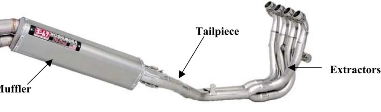
In the Formula SAE-A competition most teams employ the standard motorcycle extractors, designing only the muffler and tailpipe assemblies (Autospeed, 2004). Figure 2.8 shows the components of an exhaust system of a typical four-cylinder motorcycle engine. The fabrication of the tailpiece is required due to the difference in geometry between a motorcycle and the Formula SAE car. It can be assumed that the original extractors are retained, as there is little performance gain obtained by replacing the standard extractors (Limney, C. & J. 2002). The reason for this will be explored in greater detail in chapter 6. The design of the muffler impacts directly on the performance of an engine. Many aftermarket mufflers are available for motorcycle engines. Furthermore, the companies that produce performance mufflers allocate a significant amount of resources to the development of their products (Akrapovic, 2003). All of these manufacturers claim an increase in the output of the engine and many provide dynamometer output to validate their claims. For this reason it can only be assumed that the teams, that choice to design and construct their own mufflers, do so for financial reasons only.
Tailpiece
Extractors Muffler
(Source: Yoshimura, 2004)
2.12 Cooling System Design Requirements and Background
2.12.1 Design Requirements
The general design requirement of the cooling system of the Formula SAE car as follows:
1.
Maintain the engine within its operating temperatures;2.
Cost effective;In order to fulfil these requirements some testing procedures, to test the original motorcycle radiator, will be devised.
2.12.2 Background
In chapter 1 it was stated that the cooling system was a genuine concern when transplanting a motorcycle engine into a Formula SAE car due to the characteristics of the airflow around the cooling system. Figure 2.10 displays two common types of cooling systems. The engine on the right-hand side is air-cooled, employing fins for the method of cooling. Clearly this engine requires a strong flow of air around the fins to enable effective cooling. As the engine is usually mounted behind the driver in a Formula SAE car the fins would receive minimal airflow. Consequently air-cooled engines are rarely used in the Formula SAE competition and there were no air-cooled engines in the Formula SAE-A competition last year (Formula SAE-A, 2004). For the aforementioned reasons the engine that is selected for the USQ Motorsport car will be liquid cooled.
(Sources: Ahlstrand, A. & Haynes, J. 1998, p6.2 & Irving, P.1971 p190)
Figure 2.9 Engine cooling systems - liquid and air.
2.13 System Design Requirements
The induction, exhaust and cooling systems are all components of the engine system and all play an important role in determining the overall performance of the engine. As well as fulfilling their individual design requirements all of the engine systems must operate in unison.
2.14 Engine Development Programs
amount of industry support in terms of component supply and funding. However, this is the first year USQ Motorsport, therefore such industry support and funding has not yet been obtained. Also, given that this project encompasses many facets of engine development it is not possible to utilise the thorough analysis techniques that the more established teams use.
2.15 Conclusion
3 Methodology
3.1 Introduction
This chapter will cover the methodologies that were used in an effort to achieve the objectives that have been previously outlined in chapter 2.
3.2 Engine Selection Methodology
For the purpose of this project engines that are available ‘off the shelf’ were analysed. This approach was taken because an engine that is relatively inexpensive and reliable could be developed within the timeframe that was required. The decisions made in the Formula SAE project, like any other engineering project, are highly dependent upon the resources available. In order to complete the engine selection component of this research project it was assumed that the university had the funding to obtain the ‘optimum’ engine.
In order to select the engine the following approach was be taken:
1.
Different types of engines were researched and classified and the type of engine that best suited the Formula SAE application was selected;3.
A list of all of the suitable transplant candidates was made and the relevant data was gathered. To make this task manageable only engines that were available in the 2003 model year were analysed;4.
Mathematical models of the acceleration performance and the 75 metre times of the Formula SAE car were developed;5.
Programs were written in Matlab to perform the above calculations;6.
The output of these programs was used to compare the vehicle’s performance in each event with each engine and the optimum engine was specified;7.
Quotes from local motorcycle dealers and wreckers for the engine were obtained and a decision was made based on the financial constraints of the team;3.3 Fuelling System Design Methodology
The fuelling system was designed using the following process:
1.
A study was carried out to determine if it was feasible to implement a forced air induction system on the 2004 Formula SAE car;2.
A fuel mixture preparation system was specified. See section 3.5 for details;3.
A prototype manifold was designed and constructed. See section 3.6 for more details;4.
A restrictor was designed and tested. See section 3.7 for more details;5.
The exhaust system was designed and recommendations were given.See section 3.8 for details;
3.4 Fuel Mixture Preparation Specification
The methodology that was used to specify the fuel mixture preparation system was as follows:
1.
Carburation and electronic fuel injection were analysed and compared;2.
Cost estimates for the utilisation of electronic fuel injection wereobtained;
3.
As carburation was the only financially viable alternative, research was carried out to determine the most suitable type of carburettor for the Formula SAE car;4.
Calculations were undertaken to select the correct the size carburettor;5.
Carburettor manufacturers were contacted to obtain costing anddesign data;
6.
A selection was made based on the financial viability of each option.3.5 Intake Manifold Design Methodology
The methodology used to design the intake manifold was as follows:
1.
The USQ mechanical workshop and various workshops in Toowoomba were consulted to ascertain the fabricating methods that were available given the budget of the USQ Motorsport team;2.
Material suppliers were contacted to determine the availability of material;3.
Various configurations for the intake manifold were researched and analysed and the basic layout of the manifold was decided upon;4.
Detailed design of a prototype manifold was undertaken;5.
Sketches of the prototype were drawn and given to the USQ mechanical workshop for construction;3.6 Restrictor Design and Testing Methodology
3.6.1 Restrictor Design Methodology
The methodology that was used to design the restrictor is as follows:
1.
Research was undertaken to determine the optimum shape of the restrictor;2.
Three different shaped restrictors were designed using various standards for flow measurement devices;3.
Detailed drawings of the restrictors were drawn and taken to the USQ mechanical workshop for construction;4.
The restrictors were tested on an airflow bench;5.
The restrictors were tested on the engine;6.
The results were compared and the optimum restrictor was selected.3.6.2 Restrictor Testing
An airflow bench is commonly used in the automotive speed shops to optimise the performance of cylinder heads. An airflow bench mimics the action of an engine. The bench draws a vacuum and measures the amount of air that passes through the orifice. An airflow bench was implemented in order to verify the optimum internal shape of the restrictor. The owner of the airflow bench conducted the testing of the restrictors. The procedure that was employed is as follows:
1.
The restrictor was placed over the passage that the air is drawn through (see figure 3.2);2.
The flow range was set (see figure 3.3);3.
By adjusting the intake flow control knob the downstream pressure in the passage was regulated. The manometer was used to match the desired pressure drop with the actual pressure drop (see figure 3.3);4.
The amount of air that passed through the restrictor as percentage of the flow setting was read from the airflow meter (see figure 3.2);6.
Step 3, 4 and 5 were repeated;7.
Steps 2 to 6 were repeated using manometer readings between 10 inches H2O and 30 inches H2O at increments of 5 inches H2O;Airflow meter Manometer
Restrictor
Controls
Figure 3.1 The airflow bench used to test the restrictor.
3.7 Exhaust System Design Methodology
The methodology that was used to design the exhaust was as follows:
1.
Research was carried to determine the optimum system;2.
The exhaust system was specified;3.
Test procedures were devised.3.8 Cooling System Methodology
It can be inferred from the discussion in the previous chapters that the actual selection or design of the radiator is very dependent on the shape of the car’s bodywork. For this reason a lot of discussion with the bodywork designer was required. Once it had been agreed that the cars bodywork could be designed around the cooling system the process of designing the cooling system entailed:
1.
Finding the optimum position for mounting of the cooling system;2.
Devising test procedures to ensure that the original motorcycle radiatorwas sufficient in the car.
3.9 System Testing
In order to test the cooling and fuelling systems, the following preliminary procedure was used:
1.
The entire system was assembled without the restrictor;2.
The carburettor was tuned ‘by ear’;3.
The restrictor was added and adjustments were made to the carburettor as required;4.
The engine was observed for any signs of missing;5.
Further tests were devised.3.10 Dynamometer Testing
dynamometers was suitable. The dynamometer that is located under S-block was probably the most suitable for the application. Upon investigation it was found that in order to use it would require the design and construction of some electrical circuitry and also the design and construction of various mounts. Regrettably the technician that knew the most about this dynamometer suffered a serious medical incident, which prevented any further pursuit of this avenue. Another dynamometer is located at the USQ agricultural block. This dynamometer is used to measure the torque output of tractors. However the technician in charge of that particular dynamometer expressed concerns about the sensitivity of the measurements that it produces. The technician was also concerned that there was not anyone on campus that had sufficient knowledge of the equipment to use it properly. Further investigation failed to locate anyone that could use the dynamometer. For these reasons it was crucial to find sponsorship from an outside source.
In order to obtain sponsorship for testing purposes required several visits to various businesses. Initially the businesses were visited to obtain advise on various aspects of the engine. Once a ‘friendly’ relationship was established between the business owner and the author, sponsorship was easily obtained. Sponsorship was achieved in this way for the dynamometer testing and the airflow bench testing.
The dynamometer that the sponsor owns is classed as a chassis dynamometer. A chassis dynamometer in conjunction with a lambda meter can perform or help perform the following functions:
1.
Measurement of power and torque;2.
The carburettor can be developed;3.
Fuel efficiency can be measured;4.
Air/fuel ratios of the engine at different loads can be measured;The dynamometer would have also been useful to ascertain:
1.
Relative losses or gains made by modifying the exhaust and intake systems;Given the functions that a chassis dynamometer can perform, the use of this equipment is essential to conduct any meaningful analysis. In order to use a chassis dynamometer the car must be at least ‘rolling’ (i.e. the wheels must be able to be driven by the engine). For this reason the team was informed as soon as sponsorship for the dynamometer had been obtained. At the team meeting, a date for dynamometer testing was agreed upon. The engine systems were ready to be tested by the agreed date. Unfortunately, the team member in charge of the suspension suffered several months of dire health problems in the time leading up to the agreed testing date. Therefore the suspension systems were not designed or constructed and the car was not ready in time to do the dynamometer tests. At the time of writing the suspension was still under construction
It was thought that the engine could be put back in the motorcycle frame and tested on the dynamometer. But from an inspection of the frame it was found that the intake manifold would not fit in the frame. Therefore finding a sponsor to test the engine on an engine dynamometer was pursued. However, the search for a suitable engine dynamometer in Toowoomba was futile. Therefore for the purposes of this dissertation it was not possible to include the experimental data and analyses that would have resulted from testing using a dynamometer and lambda meter.
3.11 Conclusion
4 Engine Selection
4.1 Introduction
Upon reading the Formula SAE-A rules it is evident that the restrictions placed on competitors are very stringent. The first aim of this chapter is to gain an understanding of the fundamental principles of internal combustion engines and their design and then relate this understanding back to the Formula SAE-A competition rules. The short listed engines that fit the criteria outlined in chapter two will then be presented. This chapter will then turn to the discussion of the simulation method that was used to select the optimum engine for the competition and the results that the simulation produced. The other factors that affect engine selection will also be discussed.
4.2 Introduction to Engines
An internal combustion engine is defined as an engine in which the chemical energy of the fuel is released via burning or oxidization inside the engine and used directly for mechanical work. An external combustion engine utilises a separate combustion chamber to burn the fuel. An example of an external combustion engine is the steam engine. This paper will only deal with IC (internal combustion) engines.
been conceived and developed since the introduction of the IC engine. However the IC engine will remain a part of our society for the foreseeable future.
In recent decades society has witnessed the advent of the rotary piston engine1. Nevertheless the reciprocating piston cylinder engine principle is still the most popular among the IC engine designers of today. In the reciprocating cylinder engine a piston oscillates backward and forward inside a cylinder transferring power through the connecting rod to the crankshaft thus transforming linear motion into rotary motion. Figure 4.1 depicts the reciprocating piston cylinder engine. Valves control the flow of gas in and out of the cylinder. This is the same basic principle that Otto incorporated in the very first IC engine. However over time the IC engine has evolved in terms of efficiency with some diesel engines producing thermal efficiencies in the range of 50% as opposed to the original IC engine’s 10% thermal efficiency. This improvement in efficiency has come about due to advances in many fields such as fluid mechanics, heat transfer, materials and electronics.
(Source: Ferguson, C.R. & Kirkpatrick A.T. 2001, p2)
Figure 4.1 Crank slider model.
4.3 Classification of Internal Combustion Engines
Internal combustion engines can be classified in many different ways including:
1.
Application - Automobile, truck, motorcycle, light aircraft, marine, portable power system or power generation.2.
Basic engine design - Reciprocating engines or Rotary engines, which can be subdivided by number of cylinders or rotors and configuration.3.
Working cycle - Four-stroke, two-stroke, supercharged, turbochargedor ram air inducted.
4.
Valve or port design and location - Overhead valves, flathead, desmodromic actuation etc.5.
Fuel - Gasoline, diesel, natural gas, liquid petroleum gas (LPG) hydrogen, alcohol.6.
Method of mixture preparation - Carburettor, fuel injection which can inject fuel into the cylinder, intake port or intake manifold.7.
Method of ignition - Spark ignition or compression ignition.8.
Combustion chamber design. - Open chamber, divided chamber, hemispherical etc.9.
Method of cooling - Air (utilising fins) or Liquid (utilising a radiator).10.
Method of load control - Throttling of fuel and air together, controlof fuel alone or a combination of both.
4.4 Method of Ignition
4.4.1 Compression Ignition Engines
The CI engine is commonly called a diesel engine after its inventor Dr Rudolf Diesel. The CI engine utilises a constant pressure air cycle and employs diesel as fuel. In the compression ignition system initially only air is inducted into the cylinder. Once the air has been compressed (and hence heated) in the cylinder, diesel is injected directly into the cylinder just before combustion is intended to occur. The method of load control is achieved by manipulating the flow rate of the fuel only. Compression ignition engines utilise what is termed direct injection as the method of mixture preparation.
Maximum pressures obtained in the cylinders, in modern large diesel engines approach 7MPa which is approximately three times greater than pressures reached in SI engines (Heywood, 1988). Consequently CI engines are typically more robust in design than SI engines in order to cope with the higher stress levels in the engine that result from the higher cylinder pressures. Therefore CI engines generally have a lower power to weight ratio than SI engines. Typical applications of medium and large CI engines, is in heavy industry although they have been utilised in cars by some manufacturers, such as Mercedes. As a general rule diesel engines are not suitable for racing applications.
4.4.2 Spark Ignition Engines
4.5 Engine Operating Cycles
Internal combustion engines can be categorised in terms of their operating cycles. The two operating cycles are the four-stroke and two-stroke cycles. Both CI and SI engines can utilise either operating cycle but for the purposes of this paper all discussions will now be based around spark ignition engines.
4.5.1 Four-Stroke Engine Theory
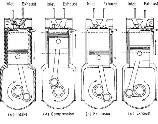
(Source: Heywood, J. B. 1988, p67)
Figure 4.2 Four-stroke operating principle.
a) Intake Stroke – As the piston lowers from Top Dead Centre (TDC) the intake valve opens and the fuel / air mixture is drawn past the throttle and intake valve into the cylinder.
c) Power Stroke – The piston is driven down due to the rapid gas expansion caused by the combustion of the fuel / air mixture. This causes the crankshaft to rotate. This is the only part of the cycle when useful work is done.
d) Exhaust Stroke – Once the piston reaches bottom dead centre the exhaust valve is opened and the spent gases are pushed through the valve due to the upward motion of the piston. The cycle is then ready to start again.
4.5.2 Two-Stroke Engine Theory
Observing the four-stroke engine we see that the four-stroke engine has only one power stroke for every two revolutions of the crankshaft. In the 1880’s the two-stroke was developed to obtain a power stroke for every revolution of the crankshaft. To demonstrate the two-stroke cycle a cross scavenge two-stroke engine. Will be considered.
Spark plug (or fuel injector)
Reed Valve
Fuel – Air
Compression Combustion & Expansion Exhaust Scavenging Ports closed Ports closed Intake port closed Intake ports open
Air inducted into Air compressed in crankcase
Crankcase (Reed valve shut)
(Source: Ferguson, C.R. & Kirkpatrick A.T. 2001, p45)
(a) During compression of the crankcase a pressure below atmospheric pressure is created in the crankcase, which opens the reed valve. The opening of the reed valve allows air to flow into the crankcase.
(b) Once the piston reverses direction during combustion and expansion begins, the air in the crankcase closes the reed valve so that the air is compressed. (c) As the piston travels further down the bore the exhaust ports are uncovered.
This allows the used gases to start to leave. In turn the cylinder pressure drops too atmospheric pressure.
(d) The intake port is opened and the compressed air from the crankcase flow into the cylinder forcing the remaining gases to leave the cylinder. This part of the cycle is termed as scavenging.
4.6 Limitations of Two-Stroke Engines
The Formula SAE-A rules specify that the car’s engine must be a four-stroke SI engine. In order to appreciate why this regulation was put in place the design objectives of the competition must be examined. According to the Formula SAE design objectives the car should be aimed at the novice weekend autocross racer. The rules also indicate that the car must have excellent performance characteristics, be inexpensive, reliable, and easily maintained whilst employing common parts (formula SAE-A Rules, 2004). With these factors in mind, two-stroke engines will be analysed.
With it high lightweight, simple design and high specific power output the two-stroke engine would seem to be the obvious choice for any high performance application. After all, the Grand Prix motorcycles adapted this type of engine up until 2002.The reason GP racers used two-stroke engine was because the two-stroke produces a lot more power than a four-stroke engine of the same cubic capacity. However the two-stroke does not produce double the power of a four-two-stroke as it theoretically should. Instead the two-stroke produces only about 50% more power (Eastwell, J. et. al. 2002, p5.57). Other drawbacks of two-stroke engines include high fuel consumption, unacceptable polluting emissions and a tendency to be noisy.
problem that arises and is characterized by a portion of the fresh air entering the cylinder exiting directly out the exhaust port. Some of the fresh air will also mix with exhaust gases and will also be wasted. Correct port and piston design can minimize these effects. Unfortunately designers have not yet been able to match the efficiency of the four-stroke engine. Due to the large amount of hydrocarbons produced by the two-stoke engine, currently no large two-stroke engine complies with US emission regulations (Ferguson, C.R. & Kirkpatrick A.T. 2001et. al., p45).
Considering the fuel inefficiency and loudness of the two-stroke it still appears a feasible option due to its high performance capabilities. Unfortunately students are employed to race the car and the ultimately the aim is to sell the car to the public. Why is this a problem? The reason lies in the power curve. From figure 4.4 it can be seen that the power curve of a two-stroke engine is quiet irregular. Initially the engine will feel quiet sluggish and then the ‘power-band’ will take effect when the throttle is rolled on. This makes the engine unpredictable and the vehicle hard for the novice to tame. To take full advantage of a two-stroke engine an expert would have to be employed to drive the car, which would defeat the purpose of this project. For this reason as well as the other characteristic problems of the two-stroke engine it can be concluded that a two-stroke engine would not satisfy the design objectives of the Formula SAE Competition.
(Source: Bianuci, S. 2003)
4.7 Summary of Engine Cycles for Formula SAE
From the preceding discussions it is clear that a SI four-stroke engine would be the obvious choice for powering a Formula SAE racing car. The four-stroke engine is the most thermally efficient and ‘cleanest’ engine expelling the least amount of hydrocarbons. Pollution is a significant design consideration as hydrocarbons from combustion form approximately half of the hydrocarbon pollution in our air. Hydrocarbons can cause cellular mutations and contribute to ground level ozone (Ferguson & Kirkpatrick, 2001). Even though the Formula SAE regulations specify that only a four-stroke engine can be employed in the competition, from the previous analysis it can be seen that the four-stroke engine is obviously the most reasonable choice. All further discussions in this paper will now be focussed on the SI four-stroke engine.
4.8 Engine Options
In the course Systems Design the author undertook research in order to find the most suitable engines for the Formula SAE car. In this research project further research was conducted but failed to uncover any other engines that would be suitable for the car. The engines that were found to be suitable for the car fall into two main categories, single cylinder enduro motorcycle engines and four-cylinder supersport motorcycle engines. The four-cylinder engines include the:
1.
Yamaha YZF – R6;2.
Honda CBR 600;3.
Suzuki GSXR 600.The single cylinder engines include the:
4.
Yamaha WR 450F;5.
Honda CRF 450F;6.
KTM EXC 525.The following engine manufacturers were considered but were found to be unsuitable:
Apart from two hundred 599cc homologation specials per year, Kawasaki currently only produces a 636cc supersport engine therefore does not fulfil the capacity criteria (Bikepoint, 2004).
Husqvarna and Rotax produce engines that fulfil all of the performance criteria. However, it was found that it is very difficult to obtain parts for these engines in a timely manner (Independent Wreckers, 2004, pers. comm. 3 Aug). For this reason it was concluded that these engines would be unsuitable for Formula SAE applications.
Harley-Davidson, BMW, Benelli, Bimota, Cagiva, Moto Guzzi, Aprilla, Ducati
and Laverda do not build engines that conform to the displacement specifications of the Formula SAE Competition (Bikepoint, 2004).
Vespa, Triumph and Hyosung do not build engines that fulfil the performance requirements (Bowdler J. 2004).
4.9 Events Related to Engine Selection
In order to select the optimum engine for the Formula SAE car it is necessary to analyse the events that engine selection impact on. Table 4.1 displays the events that the selection of the engine directly relates to.
Events Points %
Cost Analysis 50 / 100 6.9
Acceleration 75 10.3
Skid Pad 50 6.9
Autocross 150 20.6
Fuel Economy 50 6.9 Endurance Event 350 48.4
Total 725 100
Totalling 500 points the autocross and endurance events make up half of the entire competition points and 69% of the points that are directly related to engine selection. These two events are circuit-racing events and require the car to be able to accelerate from a wide range of velocities. Abundant acceleration is required so that the car can overtake and accelerate out of corners. The velocity range to be considered was set between zero and 120km/hr. This range was decided upon as the information provided by the official Formula SAE website (2004) indicates that the top speed obtainable on the track is approximately 120km/hr.
The other events that depend upon acceleration performance include the acceleration event and the skid pad event. The acceleration event is essentially a drag racing event held on a 75 metre long track. Obviously the engine that applies the greatest average acceleration over 75 metres would be optimum in this event. The skid pad event requires the car to perform figure eights around two witches hats, which are 18.25m apart, in the shortest possible time. In this event it was assumed that engines with the greatest acceleration in the lower velocity range are optimal.
The fuel economy event is weighted with 50 points and as its title suggests is scored on the cars fuel efficiency. From the rules it was found that 50 points of the 100 points allocated to the costing event related to engine selection. The remaining 50 points are awarded on the basis of the quality of the costing report and the manufacturing process discussion.
From table 4.1 and the previous discussions in this section it can be concluded that 86.2% of the points that are reliant on the engine selection are dependent on the acceleration performance of the car. In contrast fuel economy and costing total just 13.8% of the points dependent on engine design.
4.10 Vehicle Performance Modelling
torque throughout the rev range than the four-cylinder engines. As both of these parameters directly affect the acceleration performance of the vehicle it is not possible to distinguish which engine is the most suitable by only analysing the engine performance characteristics. In order to determine the engine that would optimise the acceleration performance of the vehicle a mathematical model of the car was developed. To show how the model was created the following section will give a description of the computing equations that were used.
4.11 Development of the Acceleration Performance Model
4.11.1 Assumptions
The assumptions made in the development of the acceleration model included:
1.
All of the engines will loose the same percentage of torque when the restrictor is fitted and therefore it is reasonable to compare the engines in standard form.2.
No wind or side forces are present.3.
Acceleration is limited by engine performance only.4.11.2 Equation of Motion
The arbitrary forces that are acting on a car at any time, if no side forces are present, are shown in figure 4.5.
(Source: Gillespie, T. D. 1992, p23)
The equation of motion states that:
x
x ma
F =
∑ (Eq.4.1)
where Fx is the force in the x direction;
m is the mass of the car; and
ax is the acceleration of the car in the x direction. Summing the forces in the x direction in figure 4.5 yields:
(
Fxf +Fxr)
−Rxf −Rx − Da−Wsin(θ)−Rhx = max (Eq. 4.2)
where Fxr is the total tractiv