DEVELOP A PROTOTYPE OF AUTONOMOUS UNDERWATER VEHICLE
MUHAMMAD AWIS JAMALUDDIN B. JOHARI
This Report Is Submitted In Partial Fulfillment Of The Requirements For The Bachelor Degree of Electronic Engineering (Computer Engineering)
Faculty of Electronic and Computer Engineering Universiti Teknikal Malaysia Melaka
iii
For my lovely mum, Jamaliah Binti Amad Saian and dad, Johari B. Padiman thanks for sacrifice towards my success.For my supervisor, Mr. Ridza Azri Ramlee, thanks for all
iv
ACKNOWLEDGEMENT
First and foremost, I would like to give Thanks to ALLAH SWT, for helping me. I would like to express my appreciation to my supervisor, Mr. Ridza Azri Bin Ramlee for his support and guidance throughout this whole project.
To my beloved parents who always give me support and never tired of confincing me in order to achieve my determination and finishing my study without any delay. They always support me and understand me while giving me opportunity in completing all my projects.
Besides that, I am also thankful to all the lecturers that also giving me some ideas and knowledge that can be used to accomplish the PSM project. Not forgotten to my friends who had also helped me in giving their thought, pro and contra of each of the research and result that had obtained.
v
ABSTRAK
Projek ini adalah untuk membangunkan prototaip kenderaan air berautonomi. Robot ini yang akan membantu manusia dalam melaksanakan satu set tugas yang sukar dan berbahaya yang melibatkan paras air dalam. Salah satu contoh tugas kenderaan air ini adalah mengambil sampel air di lautan dalam. Menjalankan tugas ini secara manual adalah sangat berbahaya dan boleh membawa kepada kematian. Oleh itu, teknologi kenderaan air berautonomi ini akan di bangunkan
vi
ABSTRACT
This project is to develop a prototype of Autonomous Underwater Vehicle. These type of robot that will assist human beings in performing a set of difficult and dangerous tasks that involve deep water level. One of an example tasks is take sample of water in deep sea. Performing this task manually is very dangerous and can make death. Therefore, the Autonomous Underwater is developing.
vii
CONTENTS
CHAPTER DESCRIPTION PAGE
PROJECT TITLE i
DECLARATION ii-iii
DEDICATION iv
ACKNOWLEDGEMENT v
ABSTRAK vi
ABSTRACT vii
CONTENTS viii
TABLE LISTS xii
FIGURE LISTS xiii
I INTRODUCTION
1.0 Overview
1.1 Objectives
1.2 Problem Statement 1.3 Scope of Works
1.4 Brief Explanation of Methodology 1.5 Report Structure
II LITERATURE REVIEW
2.0 Introduction
2.1 Autonomous Underwater Vehicle 2.1.1 Low Cost Technology 2.1.2 High Cost System 2.1.3 Complex System 2.1.4 Connection Variant 2.2 Servo Motor
2.2.1 Servo Motor Operation 2.2.2 Servo Wiring
2.2.3 Servo Voltage 2.2.4 Servo Current 2.2.5 Servo Velocity 2.2.6 Servo Selection 2.2.7 Servo Motor Tuning 2.3 Thruster Motor
2.4 RF Transmitter Module 2.4.1 Product Specification 2.4.2 Antenna
2.4.3 Product Layout
2.5 RF Receiver Module
2.5.1 Product Specification 2.5.2 Antenna
2.5.3 Product Layout 2.6 H-Bridge
2.6.1 The Mosfet Configuration 2.6.2 Forward Motion
2.6.3 Reverse Motion 2.6.4 No motion
2.6.5 Not Allowed Mode
2.6.6 Filtering Noise And Voltage Spikes 2.6.7 Under-Voltage Protection
2.7 Submerse Fundamental
III METHODOLOGY
3.0 Introduction
3.1 Planning Flow Chart
3.1.1 Identify Project Title
3.1.2 Collecting Project Information
3.1.3 Create and Understand Project Circuit 3.1.4 Selecting Projects Component
3.1.5 Circuit Testing 3.1.6 Design Process
3.2 Block Diagram
3.2.1 Transmitter 3.2.2 Receiver
3.2.3 Assembling The Remote Control
3.3 Power Supply
3.3.1 Circuit Description
3.4 Remote Control Encoder PT2262
3.5 Remote Control Decoder Pt2272
3.6 Thruster Motor
3.7 The Microcontroller 3.8 Vehicles Construction
iv RESULT AND DISCUSSION
4.0 Result
4.0.1 Design Process 4.0.2 Construction Process
4.2 Discussion
vii Conclusion and Suggestion
5.0 Introduction
5.1 Conclusion
5.2 Suggestion
xi
LIST OF TABLES
NO DESCRIPTION PAGES
Table 1 Type of bilge pump 17
Table 2 Type TX 315 or 433 MHz 18
Table 3 RF_ TX _ 315 and RF _ TX_433 specifications 19
Table 4 RF_TX_315MHz specifications 20
Table 5 RF_TX_433 MHz specifications 20
Table 6 Type TX 315 or 433 MHz 21
Table 7 RF_ TX _ 315 and RF _ TX_433 specifications 21
xii
LIST OF FIGURES
NO DESCRIPTION PAGES
Figure 1: Basic block diagram of project 3
Figure 2: Design of project 4
Figure 3: Actual image of the project Hexapod robot 7
Figure 4: Servo motor from Cytron 11
Figure 5: Diagram of pulse widths sent to control servo motor position 12
Figure 6: Closed-loop velocity servo 15
Figure 7: Measuring open-loop characteristic 15
Figure 8: Bilge Pump 16
Figure 9: RF_TX_315MHz 19
Figure 10: RF_TX_433 MHz specifications 20
Figure 11: RF_TX_315MHz 22
Figure 12: H-Bridge Circuit 23
Figure 13: Project methodology flowchart 30
Figure 14: Block diagram of the Autonomous Underwater Vehicles 33
xiii
Figure 16: Transmitter PCB track design 35
Figure 17: Receiver circuit 36
Figure 18: Receiver PCB track design 37
Figure 19: Power Supply circuit 39
Figure 20: PT2262 configuration 40
Figure 21: Block diagram PT2262 41
Figure 22: PT2272 configuration 42
Figure 23: Block diagram PT2272 42
Figure 24: Bilge pump that had been modified 43
Figure 25: Dimension of bilge pump 43
Figure 26: The Microcontroller PIC18F4550 pin assignments 45
Figure 27: Full schematic for PIC18F4550 45
Figure 28: Develop a prototype of AUV block diagram 46
Figure 29: The structure of the tailplane 46
Figure 30: Transmitter Circuit 49
Figure 31: Receiver circuit 50
Figure 32: H-bridge motor driver 50
Figure 33: Microcontroller circuit 51
Figure 34: The design of fin 51
Figure 35: The body of the vehicle 52
Figure 36: Actual design of the project 52
Figure 37: Design tailplane 54
xiv
LIST OF APPENDIX
NO DESCRIPTION PAGES
APPENDIX A DATASHEET REMOTE CONTROL ENCODER 60
APPENDIX B DATASHEET REMOTE CONTROL DECODER 63
APPENDIX C DATASHEET L293D 66
APPENDIX D DATASHEET SERVO MOTOR C36R 68
1
CHAPTER 1
INTRODUCTION
1.0 Overview
This project is about development of an Autonomous Underwater Vehicle (AUV). This project will be focusing on designing, modeling, system identification and control of these vehicles are still major active in these research and development. This prototype is similarity with submarine but for this prototype, it develop in the small scale and does not have operator to control.
2
1.1 Objectives
The objectives of this project are develop a prototype that able to control from surface of the sea by using wireless communication and able to submerse into the sea and will go up to the surface after a few minute.
1.2 Problem Statement
In scientific research, the precisely result must be achieve in each of the experiment that are looking for. It is impossible to diving in deep sea to take some of the sample creatures or water to doing research on that. For military, intelligent unit is the backbone for this organization and this unit must have high technologies to bring out criminal. To overcome all the problem above, this project is the best solution. Otherwise, this project also can be part of commercialization
1.3 Scope of Works
In this project, the scope of this project is to design the vehicle which has the capability to submerse and emerge with using the remote control. This project can be divided into two parts. There are mechanical and electronic. Mechanical part consists of finding material that were using in this project that is PVC as the hull and balsa wood as the fin. This is important to make the vehicle float or submerse in the water.
3
1.4 Brief Explanation of Methodology
The methodology of this project is made to determine and achieve the project objective and also to ensure it will not further from project’s scope. Before starts up on the project, literature review and background study is made. This is to ensure what, why and how the project is different from other project in previous.
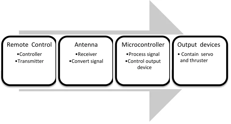
After that, the architecture, concept, requirement and the process of submarine is study and familiarize. Study on block diagram of the process operation which holds the input and output, transmitter and receiver module are made and documented. Basically the controller for this project is PIC18F4550. The inputs that will be using are the switches that places in remote control, where its control the movement of the vehicle, while the output will be connected to the servos motor at fin of the vehicle and thruster motor at the back of the vehicle.
Remote Control Antenna Microcontroller
•Controller •Receiver •Process signal
[image:19.612.152.530.378.581.2]•Transmitter •Convert signal •Control output device
Figure 1: Basic block diagram of project
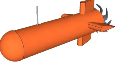
Next step for project methodology is the most crucial for underwater vehicle development. The designing the hull and fin of the vehicles is carefully design and constructed to make the movements of the underwater vehicles smoothly in water and look likely a remote control submarine. This part is most crucial because of using
Output devices
4
[image:20.612.228.423.171.286.2]mechanical knowledge to achieve this methodology. Stability, buoyancy and synchronization of all servos motor and thruster motor are still in this major. This is to ensure the fluidity of the underwater movement to move at all terrain and all direction.
Figure 2:Design of project
After designing the project, the next part is all about the electronic session with include programming, designing circuit and control the output devices. The output devices that have in this project is included servo motor and thruster motor. The servomechanisms that make the underwater vehicle turn left and turn right are actually generated by PWM signal and this make the underwater vehicle is ideally in movement. It also supported by thruster motor to make the underwater vehicle forward and reverse.
5
1.5 Report Structure
This report consists of three chapters which are Introduction, Literature Review, and Methodology.
In Chapter 1 is Introduction, it had discussed about project background, project objectives, problem statement, scope of work, short brief of project methodology and overview the remaining chapters.
In Chapter 2 is Literature Review, it had reviews some references from previous project, journals, articles, books and datasheet. All the materials was useful to success this project.
In Chapter 3 is Methodology, it discusses the way to process this project. This project was divided into two parts which are software development and hardware design. The details process for the both part will totally present in this chapter.
In Chapter 4 is Result and Discussion, is show the result and discuss the analysis that already done. This section is important to know whether this project is successful or otherwise.
6
CHAPTER 2
LITERATURE REVIEW
2.0 Introduction
In this chapter, it will discuss about the research literature, Some concept of a project is described. This because an understanding of the work will assist in preparing the project end of this year. The background study or literature review come from various resources such as:
1. Senior’s past project thesis 2. Books
3. Journals
7
knowledge and ideas about topics that have been issued and knows the strength and weaknesses of a study of the literature
2.1 Autonomous Underwater Vehicle.
Remote Operated Vehicles (ROV) have been used in the offshore industry since the late 1960s and are well established and specialized vehicles for deep water missions[1]. However, their constraints such as the need for a communications harness and a control platform have limited their use and capabilities., AUVs have stepped to the forefront of deep water exploration. AUVs are unharness, fully automated submersible platforms capable of performing underwater tasks and missions with their onboard sensor navigation and payload equipment. Despite an AUV’s increased complexity, particularly with respect to its programming, its advantages over an ROV far outweigh the added complexity of designing and building one.
[image:23.612.209.446.511.690.2]Today, the AUV industry is growing dramatically with the increase in the reliability and technical abilities of these vehicles. The goal in underwater robotics at present is to develop a prototype of AUVs . In order to accomplish this goal, much research is being carried out worldwide with particular emphasis on the designing prototype, designing electronic part and the choses of material.
8
2.1.1 Low Cost Systems
The journal that produce by references [2] which build the prototype vehicle measure approximately 24 inches long (61cm) by 3.5 inches in diameter (8.9 cm), displacing approximately 7 lbs. (3.3kg) and contained with this main propulsion system, consisting of the main propulsion motor, motor controller and propeller; power system, consisting of main battery and DC-DC converters; vehicle control system, consisting of control fins and fin servos; autopilot system, consisting of the autopilot computer, A/D converter, sensor conditioning circuits, and orientation sensors; and the structural system, consisting of the watertight hull and supporting structural components. This prototype is cost less than RM1000.
Another study done by reference [3] the structure is mainly made of PVC pipe with 17 cm diameter and 95 cm in length. The advantage of this research is it have the ballast tubes to guarantee and slightly positive buoyancy of the whole structure. The other characteristic is it have navigation that can responsible for obstacle and the self- diagnostic. The cost to build this prototype is $2400 including with the microcontroller- based architecture [3]. The cost is suitable with material and the system that were build up.