i
SMART GARDEN SYSTEM
NURSHAHNEEM BINTI MOHD SAID
This Report Is Submitted In Partial Fulfillment of Requirements For The Bachelor Degree of Electronic Engineering (Industrial Electronic)
Faculty of Electronic and Computer Engineering Universiti Teknikal Malaysia Melaka
ii
UNIVERSTI TEKNIKAL MALAYSIA MELAKA
FAKULTI KEJURUTERAAN ELEKTRONIK DAN KEJURUTERAAN KOMPUTER
BORANG PENGESAHAN STATUS LAPORAN PROJEK SARJANA MUDA II
Tajuk Projek : SMART GARDEN SYSTEM
Sesi
Pengajian : 1 0 / 1 1
Saya NURSHAHNEEM BINTI MOHD SAID
mengaku membenarkan Laporan Projek Sarjana Muda ini disimpan di Perpustakaan dengan syarat-syarat kegunaan seperti berikut:
1. Laporan adalah hakmilik Universiti Teknikal Malaysia Melaka.
2. Perpustakaan dibenarkan membuat salinan untuk tujuan pengajian sahaja.
3. Perpustakaan dibenarkan membuat salinan laporan ini sebagai bahan pertukaran antara institusi pengajian tinggi.
4. Sila tandakan ( √ ) :
SULIT* *(Mengandungi maklumat yang berdarjah keselamatan atau kepentingan Malaysia seperti yang termaktub di dalam AKTA RAHSIA RASMI 1972)
TERHAD** **(Mengandungi maklumat terhad yang telah ditentukan oleh organisasi/badan di mana penyelidikan dijalankan)
TIDAK TERHAD
Disahkan oleh:
__________________________ ___________________________________
(TANDATANGAN PENULIS) (COP DAN TANDATANGAN PENYELIA)
iii
“ I hereby declared that this report entitled Smart Garden System is a result of my own work except for quoted that have been cited clearly in the references”
Signature : ……….
Student : NURSHAHNEEM BINTI MOHD SAID
iv
“I hereby declared that I have read this report and in my opinion this report is sufficient in term of the scope and quality for the award the Bachelor of Electronic Engineering
(Industrial Electronic) With Honours”
Signature : ……….
Supervisor Name : CIK SITI AISAH BINTI MAT JUMOS@YUNUS
v
Specially dedicate to my beloved parent, En. Mohd Said b. Ali and Pn. Sa‟ae Bt Kawi and also to my siblings who give the encouragement and support for me to completed this thesis. Not forgotten to my supervisor Miss Siti Aisah Bt Mat Junos@ Yunus who gave me lot of guidance and advice throughout this project until successful. Thanks you
vi
ACKNOWLEDGEMENTS
Praise to Allah S.W.T for giving me the strength to overcome all the difficulties and letting me to finish my PSM I and PSM II. In order to undergo this final year project, there are number of people that really help me a lot, starting from beginning of the project till the end of it.
First of all, I would like to thanks to my project supervisor, Cik Siti Aisah Bt Mat Junos@ Yunus because of his guidance and advice on my project in many ways kept me going. I appreciate all his suggestions and encouragement through out the process of completing this thesis.
Special acknowledgment is payable to my Parents, En. Mohd Said b. Ali and Pn. Sa‟ae Bt Kawi who have helped me a lot throughout of the process do my project. Always support me and give me encouragement until the end of this project. To my brother and also to my sister that always stay besides me, support me when I‟m down and never give up with me.
Last but not least, this acknowledgment also goes to all my dearest friends and also to those who are directly or indirectly giving me advice and full support during developing this project till my project and my thesis complete.
vii
ABSTRACT
This project will describe about Smart Garden System. This project has four systems that will combine to each others to create a perfect combination system. This project only involves hardware only. There are three circuits that are automatic functional and one is functional in manually. The first circuit is an Automatic Water Sprinkle that functional to sprinkle the plants or flowers at the garden. This Automatic Water Sprinkler circuit is operating in automatically. Then second is LDR Sensor that will automatically switch ON the light when it detects the dark condition. The last circuit is motor canopy circuit. This circuit has two functions. First is manually
functional is the Motor Canopy Circuit prepared at the „wakaf‟ or at the chair that
functional to protect garden user from rain and sunlight. Second function is as automatic system that will operate when temperature sensor (LM35) is used. When the sensor detects heat or no heat, the canopy will open or close automatically. An automatic
function also prepared at the „wakaf‟ or at the chair. This Garden will facilitate and
viii
ABSTRAK
ix
TABLE OF CONTENT
CHAPTER CONTENT PAGE
PROJECT TITLE i
DECLARERATION ii
DEDICATION v
ACKNOWLEDGEMENT vi
ABSTRACT vii
ABSTRAK viii
TABLE OF CONTENT ix
LIST OF TABLES xiii
LIST OF FIGURES xiv
LIST OF APPENDICES xvii
CHAPTER 1 INTRODUCTION
1.1 Introduction 1
1.2 Advantages of Project 2
1.3 Problem Statement 2
1.4 Objective 3
1.5 Scope 3
1.6 Methodology 4
x
CHAPTER 2 LITERATURE REVIEW
2.1 Automatic Water Sprinkler Circuit 5
2.1.1 Description 5
2.1.2 Water Sensor (Pad) 6
2.1.3 Sprinkler 6
2.2 LDR Light Sensor Circuit 8
2.2.1 Description 8
2.2.2 LDR Sensor 8
2.2.3 LDR Light Sensor Using a Relay 9
2.2.3.1 Relays are used to and for 11
2.3 Motor Canopy Circuit 11
2.3.1 Motor Canopy Circuit (Manually) 11
2.3.1.1 Description 11
2.3.1.2 Motor Canopy (Manually) using H-Bridge Concept
12
2. 2.3.2 Motor Canopy Circuit (Automatically) 14
2.32.1 Description 14
2.3.2.2 Motor Canopy Circuit (Automatically) using Temperature Sensor (LM35)
15
CHAPTER 3 METHODOLOGY
3.1 Identify Problem Statement 19
3.2 Project Planning Using Gantt chart 20
3.3 Information Searching 20
3.3.1 Books 21
xi
3.3.3 Internet and Web Pages 21
3.3.4 Discussion with lecturer 22
3.4 Project Flow Chart 22
3.5 The Project Process 24
3.6 Etching Process to Printed Circuit Board 26
CHAPTER 4 DEVELOPEMENT PROCESS
4.1 Block Diagram for Overall Project 28
4.2 Automatic Water Sprinkler. 29
4.2.1 Automatic Water Sprinkler System with Water Sensor (Pad)
29
4.2.2 Schematic of Automatic Water Sprinkler Circuit
30
4.3 LDR Light Sensor 31
4.3.1 LDR Light Sensor with LDR Sensor 31
4.3.2 LDR Light Sensor Circuit 32
4.4 Motor Canopy 34
4.4.1 Motor Canopy (Manually) System with Switches
34
4.4.2 Schematic of Motor Canopy (Manually) Circuit
35
4.4.3 Motor Canopy (Automatically) System with LM35
37
4.4.3.1 Description of Motor Canopy (Automatically) Components
38
4.4.4.1 REG 7805 Voltage Regulator 39
4.4.4 Schematic of Motor Canopy (Automatically) Circuit
xii
CHAPTER 5 RESULTS AND DISCUSSION
5.1 Project Analysis 42
5.1.1 Automatic Water Sprinkler 43
5.1.2 LDR Light Sensor 45
5.1.3 Motor Canopy 46
5.1.3.1 Motor Canopy (Manually) 46
5.1.3.2 Motor Canopy (Automatically) 47
5.2 Results 48
5.2.1 Automatic Water Sprinkler 48
5.2.2 LDR Light Sensor 51
5.2.3 Motor Canopy 52
5.2.3.1 Motor Canopy (Manually) 52
5.2.3.2 Motor Canopy (Automatically) 55
CHAPTER 6 CONCLUSION
6.1 Conclusions 58
6.2 Future Work 59
REFFERENCES 60
xiii
LIST OF TABLES
NO TITLE PAGE
2.1 LM 35 Voltage output temperature sensors 17
5.1 Soil Condition 49
5.2 LDR Condition 52
xiv
LIST OF FIGURES
NO TITLE PAGE
1.1 Methodology Overview 4
2.1 Water sensor 7
2.2 Sprinkler 8
2.3 LDR Sensor 10
2.4 Relay 11
2.5 AC coil relay 11
2.6 Switch 1, Switch 2 and Switch 3 13
2.7 H-Bridge Circuit 13
2.8 Typical solid state H-bridge 14
2.9 LM 35 DZ is a 3-pin sensor 17
2.10 (a) Bottom view of LM 35 (b) LM 35 Temperature
Sensor
18
3.1 Flow Chart of the Overall Project 24
3.2 Flow Chart Process 26
3.4 Step for Etching Process 27
4.1 Block Diagram for Overall Project 29
4.2 Automatic Water Sprinkler system with Water Sensor
(pad)
30
4.3 Overall circuit for Automatic Water Sprinkler 31
4.4 PCB Layout of Automatic Water Sprinkler 32
xv
4.6 Overall circuit for LDR Light Sensor 34
4.7 PCB Board of LDR Light Sensor 34
4.8 Motor Canopy (Manually) circuit with Switches 35
4.9 Overall circuit for Motor Canopy (Manually) 36
4.10 PCB Layout of Motor Canopy (Manually) 37
4.11 Motor Canopy (Automatically) circuit with LM35 38
4.12 REG 7805 Voltage Regulator Circuit 40
4.13 REG 7805 40
4.14 Overall circuit for Motor Canopy (Automatically) 42
4.15 PCB Layout of Motor Canopy (Automatically) 42
5.1 Smart Garden System 44
5.2 Automatic Water Sprinkler System 45
5.3 Automatic Water Sprinkler PCB board 45
5.4 LDR Light Sensor System 46
5.5 LDR Light Sensor PCB board 46
5.6 Motor Canopy (Manually) System 47
5.7 Motor Canopy (Manually) PCB board 47
5.8 Motor Canopy (Automatically) System 48
5.7 Motor Canopy (Automatically) PCB board 48
5.8 Water sensor (Pad) 49
5.9 LED is ON 50
5.10 Sprinkler is sprinkle the water to the plant 50
5.11 LED is OFF 51
5.12 Sprinkler stop sprinkle the water to the plant 51
5.13 LED is OFF 52
5.14 LED is ON 53
5.15 Switches in Motor Canopy (Manually) system 54
5.16 LED is ON in Green Color 54
5.17 LED ON in Green Color and CD-ROM is Cover 55
5.18 LED is ON in Red Color 55
xvi
5.20 LED and Buzzer is OFF 57
5.21 CD-ROM is Open 57
xvii
LIST OF APPENDICES
NO TITLE PAGE
A Gant Chart 63
B1 Voltage Regulator (REG 7805) Datasheet 66
B2 IC Timer NE555 Datasheet 69
1
CHAPTER 1
INTRODUCTION
This chapter will briefly discuss on the project overview. The project introduction, problem statement, scope, objective, methodology and report outline will be presented in this chapter
1.1 Introduction
This project is application based on the electronic circuit that applied at the garden which has functional automatically and manually. „Smart Garden System‟ is a model or a prototype for a real project on a large scale. In this prototype, there are four systems that will combine to each others to make a perfect combination system. This System only involved hardware part.
2
The second system is LDR Light Sensor is to detect the light. When the garden is in dark condition, this LDR Sensor circuit will automatically light ON the lamp. Otherwise, when the garden is light or in bright condition, the light will automatically OFF the lamp.
Then the last system is the Motor Canopy Circuit is functional either automatic system or manual system. For automatic action, it functions when the canopy detects heat, then the canopy will automatically open and it will automatically close, when there is no heat detect. For manual action, it depends on the owner or the users of the garden. This circuit is important during the rain season that can provide shelter at
„wakaf‟ for user to rest and hanging out.
1.2 Advantages of Project
For Smart Garden System there are several advantages for the user. First advantages for smart garden it can produce comfortable to the users by endow with
shelter at „wakaf‟. Second advantage is in term of save energy and cost-effective. That
is because the LDR sensor and Water Sensor (Pad) are used.
1.3 Problem Statement
3
1.4 Objective
There are several objectives need to achieve in this project:
1. To create Smart Garden System that easy to manage
2. To develop four systems: 1) Automatic water Sprinkler System 2) LDR Light
Sensor System 3) Motor Canopy System (Manually) 4) Motor Canopy System (Automatically).
1.5 Scope
Smart Garden System will involve for hardware system only. It will have 4 circuits that connected with each other. For Automatic Water Sprinkler, the components that have been used are water sensor (pad), water pump, sprinkler, relay and IC Timer 555. For LDR Light Sensor, the components that have been used are LDR (Light Dependent Resistor) sensor, relay and. For Motor Canopy the component that have been used are temperature sensor (LM35), CD-ROM, LED (Light Emitting Diode), buzzer, operational amplifier IC CA3140, IC CD4001, fuse, and voltage regulator REG 7805.
4
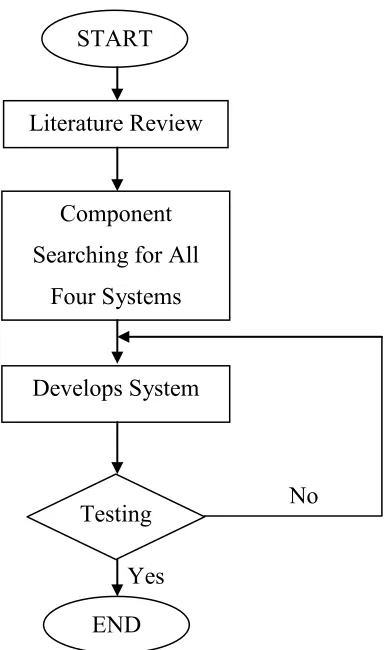
[image:21.612.251.445.110.435.2]1.6 Methodology
Figure 1.1: Methodology Overview
1.7 Report Outline
This report is organized into six chapters and the outline of each chapter is explained briefly as follows.
Chapter 1 is the introduction of the project which discusses the objectives, project advantages, problem statement and scope of the project.
Yes START
Literature Review
Component Searching for All
Four Systems
Develops System
Testing
END
5
Chapter 2 is the literature review of the project. All the theoretical and the basic idea for the project are explained in detail manner.
Chapter 3 is describing the methodology of the project. In this chapter shows the planning of project implementation. This chapter also explains in detail the methods that have being selected.
Chapter 4 will explain the development process for the project. This chapter also will show the equipment involve to accomplish this project.
Chapter 5 is the project result. This chapter consists of discussion and analysis of the project results.
6
CHAPTER 2
LITERATURE REVIEW
In this chapter, it will give information and described all components that involve in Smart Garden System project. The major components consist is water sensor (pad), water pump, LDR sensor, LED, relay, H-bridge circuit, temperature sensor and CD-ROM. This component will help to develop the Smart Garden System.
2.1 Automatic Water Sprinkler Circuit
2.1.1 Description
This circuit is functional as automatic system that depends on the garden soil condition. This circuit is important to the plant, it can keeping moister to the plant.
7
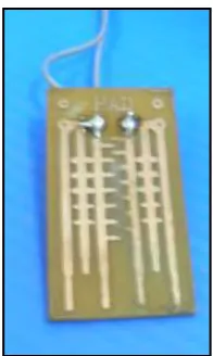
2.1.2 Water Sensor (Pad)
[image:24.612.279.377.276.440.2]Water sensor (pad) is able to monitoring soil water content. Because this pad measures the dielectric constant of the soil using transmission line techniques, it is insensitive to water salinity, and will not corrode over time as does conductivity based probes. This probe is small, rugged, and consume under a milliamp of power. This pad also has a rapid response time. They can be inserted and take an accurate reading in under 1 second. Water sensor (pad) has an output range of 0 to 3V related proportionally to water content.
Figure 2.1: Water sensor (pad)
2.1.3 Sprinkler
Sprinkler is an important part of automatic water sprinkler. It is usually installed inside the building and structures with light fire danger, medium fire danger and heavy fire danger, such as workshop, warehouse, hotel, shop, recreational place, hospital, cinema, office building and garage.