DESIGN AND DEVELOPMENT OF CARBON FIBER SUSPENSION PUSH ROD FOR UTeM FORMULA STYLE RACE CAR
MOHAMAD FIRDAUS BIN ABDUL GHAFFAR
This technical report is submitted in accordance with the requirements of the Bachelor of Mechanical Engineering (Automotive)
Faculty Mechanical Engineering University Technical Malaysia Malacca
ii
DECLARATION
“I hereby, declare this thesis entitled Design and Development of Carbon Fiber Suspension Push Rod for UTeM Formula Style Race Car is the result of my own
research except as cited in the reference”
Signature : ………
iii
DEDICATION
To my beloved family especially my father, Abdul Ghaffar B. Daud
And also to my beloved mother, Jawahair Binti Ahmad
iv
ACKNOWLEDGEMENT
Alhamdulillah and Thank to Allah S.W.T. with all His Gracious and His Merciful forgiving me strength and ability to accomplish this research project successfully. Firstly, I would like to express my deep and sincere gratitude to my supervisor, Mr Muhd Ridzuan Bin Mansor. His wide knowledge and his logical way of thinking have been of great value for me. His understanding, encouraging and personal guidance have provided a good basis for the present project.
I warmly thank to my beloved parents and family who always pray and encourage me while pursuing my study and project. My sincere thanks are due to Faculty of Mechanical Engineering, Universiti Teknikal Malaysia Melaka because give me a chance to gain a lot of knowledge, experience and also helping me with my research and project.
v
ABSTRACT
vi
ABSTRAK
vii
TABLE OF CONTENT
CHAPTER CONTENT
DECLARATION DEDICATION
ACKNOWLEDGEMENT ABSTRACT
ABSTRAK
TABLE OF CONTENT LIST OF FIGURES LIST OF TABLES NOMENCLATURE
CHAPTER I INTRODUCTION
1.1 Introduction of Formula Race Car
1.2 Problem Statement
1.3 Objective
1.4 Scope of Project
1.5 Expected Result
CHAPTER II LITERATURE REVIEW
2.1 History Formula SAE
2.2 Formula Student Car specification
2.3 Suspension
2.4 Push rod suspension system
viii
CHAPTER CONTENT
2.5 Composite Material
CHAPTER III RESEARCH METHODOLOGY
3.1 Introduction
3.2 Process Planning
3.3 Theory of Suspension Load
Calculation
3.4 Composite Calculation
3.5 Design Suspension Push Rod
3.6 Fabricate the Push Rod
Suspension
3.7 Compression Test
CHAPTER IV LOAD ANALYSIS
4.1 Suspension Push Rod Load
Analysis
4.2 Position of Center of Gravity
4.3 Composite Calculation
CHAPTER V FABRICATION PROCESS AND
COMPRESSION TEST OF
COMPOSITE SUSPENSION PUSH ROD
5.1 Introduction
5.2 Fabricating Carbon Fiber and
Glass Fiber Suspension Push Rod
ix
CHAPTER CONTENT
5.3 First Stage of Fabrication Process
5.4 Second Stage of Fabrication
Process
5.5 Compression Test for Composite
Push Rod Suspension
CHAPTER VI RESULTS AND ANALYSIS
6.1 Introduction
6.2 Compression Test Analysis
6.3 Load Analysis
6.4 Fabrication Process Analysis
6.5 Joining Process Analysis
6.6 Testing Error Analysis
6.7 Area of Failures Analysis
6.8 Weight of Composite Suspension
Push Rod Analysis
CHAPTER VII CONCLUSION AND FUTURE
RECOMMENDATION
7.1 Conclusion
7.2 Future Recommendation
x
LIST OF FIGURE
NO. TITLE
1.1 Student Formula Race Car 2.1 Type of Suspension System 2.2 MacPherson Strut Suspension
2.3 Double Wishbone Suspension System
2.4 Camber Angle
2.5 Caster Angle
2.6 Toe Pattern
2.7 De Dion Tube Suspension Systems
2.8 Push Rod Suspension System 2.9 Honda RA106 Push Rod 2.10 Euler Case of Buckling 2.11 Euler Case of Buckling 2.12 Demonstration of Euler Case 2.13 Woven glass fiber
2.14 Carbon fiber woven 2.15 Hand Lay-Up Process 2.16 Spray-up Process
2.17 Basic Vacuum Bag Process 2.18 Resin Transfer Molding
3.1 Flow Chart Overall PSM Process
3.2 Normal Force on Tire at Static Condition 3.3 Forces at Inclination Position
xi
NO. TITLE
3.4 Forces during Braking
3.5 Force on the Suspension System 3.6 Force Acting on Suspension Link
3.7 Flow Chart Designing Push Rod Suspension 3.8 Measured Drag Coefficients
3.9 Concept Design I 3.10 Concept Design II 3.11 Concept Design III 3.12 Concept Design IV 5.1 Carbon Fiber Woven
5.2 Glass fiber woven and CSM 5.3 Mold release wax
5.4 Weighted the weight of polyester resin and hardener 5.5 Add hardener to the resin about 99:1 weight ratio 5.6 Applying the mold release wax on the surface of the
mold
5.7 Applying one ply of woven carbon fiber
5.8 Applying the resin on the surface of woven glass fiber
5.9 Rolled the layer using roller to remove the entrapped air
5.10 Placing the joint
5.11 Mark the cutting area at the specimen
xii
NO TITLE
5.13 INSTRON universal test machine
5.14 Compression test for composite push rod suspension
6.1 Compression test for Fiber Glass (First Specimen) 6.2 Compression test for Fiber Glass (Second
Specimen)
6.3 Compression test for Carbon Fiber (First Specimen) 6.4 Compression test for Carbon Fiber (Second
Specimen)
6.5 Carbon fiber push rod suspension after conduct testing
6.6 Push rod joining 6.7 Fabricating process 6.8 Universal joint after grind
6.9 INSTRON universal test machine
6.10 Ball joint end surface is machined flat and a tape is placed to prevent part from sliding during test. 6.11 Recommended jig for compression test
6.12 Fiber glass specimen 6.13 Carbon fiber specimen
6.14 Specimen for GFRP and CFRP fail at gage area 6.15 Weighting the specimen
6.16 Weighting the universal joint
xiii
LIST OF TABLES
NO. TITLE
2.1 Car Specification 2.2 Kevlar Properties
2.3 Comparative yarn properties for Fiber reinforcement plastic
2.4 The comparison between Polyester and Epoxy resin 3.1 The Rating of Push Rod Design
4.1 Total Load for Push Rod
6.1 Maximum Force subjected between to Glass Fiber Push rod and Carbon Fiber push rod before failure 6.2 Weight between Glass Fiber and Carbon Fiber 6.3 The universal weight
6.4 The net weight of specimen
PAGE
6 20
23 30 44 53
xiv
NOMENCLATURE
SAE = Society of Automotive Engineers UTeM = Universiti Teknikal Malaysia Melaka
GPa = Giga Pascal
kPa = Kilo Pascal
CATIA = Computer Aided Tridimensional Interactive Application
CAD = Computer-aided Design
= Stress, MPa
ASTM = American Society for Testing and Materials
M = Mass, kg
L = Length, m
c = Centre to rear axle, m
b = Centre to front axle, m
W = Weight, N
Ff = Force at the front, N
h = Centre of the gravity
a = Acceleration, ms-2
Ftire = Force at the tire, N Lateral force = Force, N
KTf = Front roll stiffness, Nm2/deg KTr = Rear roll stiffness, Nm2/deg ay = Acceleration in lateral, ms-2 Δ = Weight transfer due to the roll, N
1
CHAPTER I
INTRODUCTION
1.1 Introduction of Formula Race Car
The Formula SAE competition is designed to give engineering students the opportunity to design, fabricate, test and race formula style racing cars. At the FSAE competition, each car is judged against the competitors to decide which team’s car best achieves the goals. The cars are judged in static design, dynamic abilities and track performance. The static events include categories such as production cost analysis, design, and a marketing presentation. The dynamic events include skid-pad and acceleration performance tests. After finish builds a car, it will test the car at the track to see the limit abilities of the car.
Nowadays, the formula student race car has makes a lot of improvement especially in term of weight from the heavyweight body chassis, suspension and others components. This is because the optimum powers to weight ratio could increase the performance especially in ride and handling performances. Before this, the components such as suspension system use steel and metal. Currently, many race car components use composite material such as carbon fiber and fiber glass to reduce the weight of vehicle.
2
[image:16.612.157.501.164.332.2]important reason using composite material at the suspension system is the handling performances. Reducing the weight of the components can give a higher performance to car (Savage, 2008).
Figure 1.0: Student Formula Race Car
(Source: http://www.3trpd.co.uk/images/casestudies/race-car-big3.jpg)
1.2 Problem Statement
3
1.3 Objectives
The objective of this project is to design and develop carbon fiber-polyester composite suspension push rod for UTeM Formula Style race car.
1.4 Scope of Project
The scopes of the projects are:
1. To calculate the load acting on the component during operation 2. To perform composite laminate analysis
3. To produce detail design of the component using 3D CAD software 4. To fabricate the component using carbon fiber and polyester matrix 5. To perform compression test to evaluate the component performance
1.5 Expected Result
4
CHAPTER II
LITERATURE REVIEW
2.1 Formula History
The first SAE Mini-Indy was held at the University of Houston in year 1979. The competition was inspired by a how to article that appeared in Popular Mechanics magazine. The competition used Mini Baja as a guide and it has to design and build small, “Indy-style” vehicles using the same stock engine. For the first time the competition is held, thirteen schools had entered and eleven compete.
Three students from University of Texas at Austin saw the potential and proposed a new mini-Indy with new rules. The new rules kept restriction to a minimum, any four –stroke engine with a 25.4 mm intake restriction. The University of Texas at Austin hosted the competition through 1984. In 1985, the competition was hosted by The University of Texas at Arlington. There, Dr. Robert Woods, with guidance from the SAE student activities committee, changed the concept of the competition from one where students built a pure racing car, to one that mirrored the SAE Mini-Baja competitions, where they were to design and build a vehicle for limited series production.
5
economic pressure, ceased to exist. The event is now funded by SAE through company sponsorships and donations along with the team's enrollment fees. (http://en.wikipedia.org/wiki/Formula_SAE)
2.2 Formula Student Car Specification
6
Table 2.1: Car Specification (Source: http://student.sae.org/, 2008)
2.3 Suspension
7
2.3.1 History of Suspension
In 16th century, a few researchers tried to solve a problem of feeling every bump in the road. For example is wagon, by slinging the carriage body from leather straps attached at four post of chassis that looked like unturned table. The term carriage body suspended from chassis is called suspension. Gottlieb Daimler in Germany and some European car makers had tried to apply coil springs. However, most manufacturers stood fast with leaf springs which less cost, easy to produce and also easy to assemble to the car. After that, in 1804, Obadiah Elliot from London was invented the venerable leaf spring, which today some manufactures still use in rear suspensions. In 1934, General Motors had introduced a coil spring suspension with each tire sprung independently (Zakaria, 2006).
2.3.2 Function of Suspension System
The suspension system works comprise of unsprung mass which is tyre mass, wishbone, spring, damper, wheel knuckle (king pin) and tie-rod for front suspension. Frame or unitized body, wheels, wheel bearings, brake system and steering system. All the components in these system are working together in order to provide a safe and comfortable mean of transportation. The suspension system functions are as follows:
i. Support the weight of the frame, body, engine, transmission, drive train, passengers and cargo.
ii. Provide a smooth, comfortable ride by allowing the wheels and tires absorb vibration due to uneven road surface while maintain the body.
iii. Work with the steering system to help keep the wheels in correct alignment.
8
v. Allow rapid cornering without extreme body rolls (vehicle leans to one side).
vi. Allow the front wheels to turn from side to side for steering.
The suspension system must consider the dynamics of moving vehicle from two perspectives:
i. Ride – ability of vehicle to smooth out bumpy road
ii. Handling – ability of vehicle to perform safely during acceleration, braking and also cornering.
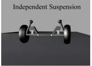
[image:22.612.151.306.375.486.2]2.3.3 Type of Suspension System
Figure 2.1: Type of Suspension System (Source: http://www.autospeednet.com/sites, 2008)
9
with one wheel can affect the wheel on the opposite side. Also in addition, if one wheel gets stuck, a lot of traction will lose because the opposite wheel does not adjust to the terrain and sit flat on the surface. The example for non-independent is De Dion tube.
[image:23.612.205.440.251.427.2]2.3.3.1 MacPherson Strut System
Figure 2.2: MacPherson Strut Suspension
(Source: http://www.carbibles.com/suspension_bible.html)
10
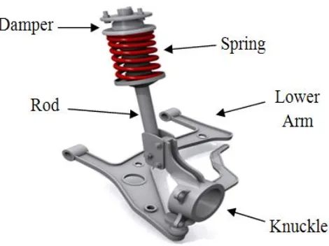
[image:24.612.183.465.145.304.2]2.3.3.2 Double Wishbone System
Figure 2.3: Double Wishbone Suspension System
(Source: http://www.carbibles.com/suspension_bible.html)
In double wishbone suspension, it is using two parallel wishbone-shaped arms to
locate the wheel. Each wishbone (or arm) has two mounting positions to the chassis and
one joint at the knuckle. The shock absorber and coil spring mount to the wishbones to
control vertical movement. Double-wishbone designs allow the engineer to carefully
control the motion of the wheel throughout suspension travel, controlling such
parameters as camber angle, caster angle, toe pattern, roll center height, scrub radius,
scuff and many more (Wikipedia, 2006).
Camber angle is the angle made by the wheel of an automobile between the
vertical axis of the wheel and the vertical axis of the vehicle as it viewed from the front
or rear. This is for designing the steering and suspension system. If the top of the wheel
is further out than the bottom, it is called positive camber and if the bottom of the wheel
is further out than the top, it is called negative camber (www.madabout-kitcars.com,