Current Source Back to Back Converter for Wind Energy Conversion Systems
I. Abdelsalam, G.P. Adam, and B.W. Williams
Abstract ─ This paper proposes a new back-to-back current source converter (BTB-CSC) suitable for
medium-voltage high power wind energy conversion systems (WECS). It employs a dual three-phase permanent magnet
synchronous generator and two current source inverters with a phase-shift transformer at the grid side. The
proposed BTB-CSC has the following advantages: reduced power circuit and control complexity; low switching
losses (zero switching losses at the inverter side); and independent control of active and reactive power.
PSCAD/EMTDC simulations are used as to assess the steady-state and dynamic behaviour of the proposed
system under different operating conditions. It is shown that the proposed WECS can ride-through ac faults.
Experimental results from scaled prototype of the proposed WECS are used to validate the simulations.
I.
Introduction
Variable speed wind turbine systems are used to increase the kilowatt-hour production of wind turbine
generators and their efficiencies and to reduce mechanical stresses on the drive train[1]. The doubly fed
induction generator (DFIG) with a fractionally rated frequency converter between the grid and its rotor
windings; and permanent magnet synchronous generators (PMSG) with a fully rated BTB converter are
commonly used in variable speed WECSs. The use of permanent magnets (PMSG) is attractive because it
reduces generator weight and increases reliability due to the absence of slip rings and brushes. The drive train
technology for variable-speed synchronous generator based WECS can be classified to: direct drive train,
Medium speed drive-train, and High speed drive-train[2, 3].
The PMSG output voltage and frequency vary with generator speed; therefore, the generator side converter must
be able to operate at variable input ac voltage and frequency. Full scale BTB power converters are used to
produce a constant frequency and voltage to meet load or grid requirements. Early generation multi-megawatt
conventional variable speed WECS used BTB two level voltage source converters (VSC) [4-7]. A cheaper
alternative being suggested for low power ratings employs WECS that consists of a diode rectifier at the
generator side, a boost chopper as an intermediate stage to perform maximum power tracking, and a PWM VSC
at the grid side [8, 9]. In some cases, the BTB VSC is realized by Z-source inverters [10]; where the
generator-side converter is a three-switch buck-type rectifier and the grid-generator-side is a Z-source inverter. The use of high
WECS employ a multilevel neutral-point-clamped converter to reduce the voltage stress on the power switches
and bulky ac filters at the grid side [11, 12].
With the use of multiphase machines, rated power of wind generators could be increased, and additional
advantages can be obtained, such as reduced pulsating torque and current per-phase compared with three-phase
of a similar rated power, lower the dc-link current harmonics, and higher reliability, with the possibility of fault
tolerant operation [13-16]. A comparison between the three-phase PMSG and the dual three-phase based PMSG
in WECSs presented in [13, 14, 16] showed that the proposed WECS reduces the pulsating torque and the dc
current ripple by (30%~40%), efficiency increased by 3%, reduced link inductance, and much higher
dc-voltage can be produced from the dual diode rectifier (which means lower boost converter losses).
Reference [17] proposed a frontend converter for variable speed WECS that uses a dual three-phase PMSG with
a dual parallel voltage source rectifier (VSR), where the rotor speed is estimated from the generator output
voltage. The main limitation of this approach is that it does alleviate the problem of high-voltage stresses being
exerted on the machine winding due switching of the VSR. Instead of parallel connection of VSR, [18]
connected the two VSRs of the frontend converter in series to halve the voltage stresses on the winding of the
six-phase generator. Although this approach is suitable for multi-MW application, it requires a complex control
strategy to cope with variable frequency operation, and a number of self-commutated switches. The authors in
[19] presented a reduced switch count WECS by using two half-controlled ac-dc converters to interface with the
dual three-phase PMSG. This solution is attractive as it reduces the converter cost and losses by replacing six
composite switches (IGBT plus anti-parallel diode) with six diodes. Despite the modification introduced to the
power circuit, the authors show that this proposed dual half control converter can control both active and
reactive power, with no torque ripple provided the sum of the generator currents of each phase is sinusoidal. An
alternative solution based on full scaled BTB dual CSC WECS is proposed in [20], which operates at a low
switching frequency (350Hz). The heavy components such as a grid-side transformer and dc-link inductance can
be placed at the bottom of the wind turbine tower for ease of installation and access. However, the use of a dual
three-phase CSR increases the cost and control complexity of the generator side converter. Therefore, the
alternative three-phase BTB CSC presented in [21, 22] is attractive as it reduces power circuit and control
complexity. But it is not suitable for multi-MW variable speed WECSs due to using a three-phase uncontrolled
diode rectifier, which cause high 5th and the 7th current harmonics in the generator side (high pulsating torque),
This paper introduces an improved version of the dual three-phase BTB CSC based converter presented in [21]
and explorers its application in WECS. The proposed WECS in Fig.1 (a) retains all the attributes of the WECS
presented in [22], plus elimination of low frequency pulsating torque in the PMSG. Its operation and control is
detailed and is substantiated using PSCAD/EMTDC simulation and experimentation on scaled prototype.
Performance of the proposed WECS during LVRT is examined using simulation.
II.
Proposed WECS
a. Proposal WECS Description and Modes of Operation
Fig. 1(a) shows the proposed WECS that consists of a wind turbine with its medium-speed drive train and dual
three-phase PMSG, with its generator-side C-filters (Cg) connected to the inputs of the proposed BTB current
source converter. The outputs of the proposed BTB converter are grid connected through C-filters (Cf) and a
three-winding phase-shift transformer. The proposal BTB converter has two operating modes, depending on the
state of the active switch Sr. The first mode is when switch Sr is on (the dc-side inductor Ldc energized); the
dc-link inductance current IL rises. In this mode, IL is equal to the switch Sr current Is, which is drawn from the dual
three-phase PMSG through the two cascaded three-phase bridge rectifiers, with no current at the input of the
dual CSI (Ii=0). The second mode starts when switch Sr turns off (dc-link inductance de-energised), with dc-side
inductor current IL falling and equal to input current of the dual CSI (Ii=IL). During the second mode, the input
currents of the generator side converter iabcr1=iabcr2=0, and the generator side C-filters Cg are used for filtering
and short duration temporary energy storage. Similarly, when Ii=0 in the first mode, the grid side C-filters Cf1
are used for filtering to ensure that continuous sinusoidal currents are injected into grid.
With a medium voltage PMSG, the switch Sr experiences high voltage stresses; thus requires series connection
of several semiconductor switches. [23] proposed a solution to this issue, where the dc-side inductor was
replaced by two equal inductors (Ldc1 = Ldc2), then the voltage stress are equally shared by the two switches.
Another solution is to use two independent sets of the three-phase BTB CSC as proposed in [21, 22] and shown
in Fig. 1(b), where the high voltage stress is shared between switches (Sr1and Sr2) and the durability of the
proposes WECS is increased, since in the case of half a generator winding failure or one converter set failure,
the WECS can continue operating at half rating, with minimum interruption.
Switches Sr1 and Sr2 receive the same gating signal, and operation of the modified converters shown in Fig. 1(b)
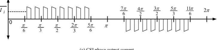
b. Dual CSI Output Current Harmonics Cancellation.
The proposed dual-bridge CSI in Fig. 1(a) injects power generated by the dual PMSG into the grid by
modulating the dc-side inductor average currentIL. This means that although instantaneous current at the input
of the dual CSI Ii is discontinuous, its average 𝐼̅𝑖over one fundamental period is constant. The dual CSI is
switched at the fundamental frequency 50Hz, and the phase-shift transformer, cancels the 5th, 7th, 17th, 19th, 27th,
31st, etc. harmonic currents component, while the inverter side C-filter has two functions: first it makes the dual
CSI output current continuous, and second, removes the 11th and 13th harmonic components from the dual CSI
output current. The phase output current of the dual-bridge CSI is shown in Fig. 1(c). To ensure zero switching
losses at the dual CSI, the switching instants of the dual CSI devices must coincide with zero input dc link
current Ii=0 (first mode), which is determined by the modulation of switch Sr. This requirement imposes the
restriction that the ratio of the switching frequency of switch Sr to the grid frequency must be an integer multiple
of 3 (in other words, integer number of pulses per 120o) as discussed in [21, 22].
(a) Proposal WECS
(b) Modified version of the proposal WECS
Gearbox ii1
ii2
IL
Is Sr ig1
ig2
Cg
Cg C
f
Cf
is
is2 is1
Y Y Δ Ldc
Ii
Dual three-phase PMSG
Sd
Rd
Gearbox
ii1
ii2
IL2 Is2 ig1
ig2
Cg Cg
Cf
Cf
is
is2 Y
Y Δ
Ldc
2
Ii1
Dual three-phase PMSG
Rd1
Ii2
Sr2 Sr1
Ldc1 Is1
IL1
Sd1
Rd2 Sd2
(c) CSI phase output current.
Fig. 1 Proposal WECS, modified versions, and CSI phase output current.
c. Dual Three-Phase PMSG Model
The dual phase PMSG being studied in this paper is comprised of two symmetrical sets of isolated
three-phase windings a1b1c1 and a2b2c2, shifted by 30°[18]. It is assumed that the stator windings are uniformly
distributed and the magneto motive force is sinusoidal distributed in the generator air-gap, so that there are no
higher order spatial harmonics. The generator is assumed to be round rotor or saliency is neglected by setting the
direct and quadrature inductances equal (Ld = Lq) [17]. The stator voltage vg, current ig and flux ѱ are described
by equations.
[ ]v = - R ig [ ][ ]-g d[ ]ψ
dt (1)
sf Li
(2)
where
1 1 1 2 2 2 T
g a b c a b c
v v v v v v v
1 1 1 2 2 2 T
g a b c a b c
i i i i i i i
6 6
R rI
Ψ: flux linkage
Ψsf: permanent magnet rotor flux linkage
r: stator resistance
Representation of a dual three-phase PMSG in the dq0 reference frame was described in [20]. The flux linkage
matrix ,the generator voltage equation in the stationary dq0 frame, the electrical rotor speed ωe, and
electromagnetic torque Teare shown in equations (3), (4), (5), and (6) respectively.
i I
0
6
3
2
2
3
5
6
7 6 42
3
1 2
1 2
1 2
1
1 1 1 2 2
1 0 01 2
2
2 1
2
2 1 2 1 2
0 02 1
3 2
3 2
3
3
d d s s d coup
d
q q q s s q
o s o
d
d d s s d coup
q
q q s s q
o
s o
L i M i F
L i M i
L i M i
L i M i F
L i M i
L i M i
(3)
1
1
1
2
2
2
1 1 1
1 1 1
01 01
2 2 2
2 2 2
02 02 0
gd d d e q
gq q q e d
go
d d e q
gd
q q e d
gq g
v ri p
v ri p
v ri p
ri p
v
ri p
v
ri p
v
(4)
e pn g
(5)
1 1 1 1 2 2 2 2
( )
e n d q q d d q q d
T p i i i i (6)
where
Fcoup: maximum magnetic coupling coefficient between rotor and stator
p: differential operator
Ld: direct-axis inductance
Lq: quadrature-axis inductance
Ms1s1: mutual inductance coefficient
ωg: generator shaft speed, rad/s
pn: number of pole pairs
d. MMF produced by Harmonic Currents of Generator Side Converter
The MMF produced by the generator current in the air gap is [24]:
sin
MMF Ni (7)
where N: number of turns, ig stator current, and θ is the mechanical angle.
The analysis of the MMF produced by the generator side converter harmonic currents is carried out in two steps:
First step: mathematically analyse the unwanted low frequency harmonics (5th and 7th) generated as a
consequence of the switching process of Sr. In [25] the three-phase ac-dc buck-boost rectifier input current
12
_ _
0
1 1
_
( 1) 1
0
2 3
1
2 3 1 4 1
( ) sin sin cos
3
4 1 sin sin( ) sin( )
L L
r c
n m
j n
L
c m n
I I
i t n t m m t
n m
I m n e m n t
nm
(8)
where:δ is the switch duty cycle such that 0 ≤δ≤ 1, 𝐼̅𝐿 is the average dc-link inductance current, m and n are the
orders of the carrier and baseband component harmonics respectively.
The first summation in equation (8) defines the fundamental frequency harmonics which include the
low-order undesired harmonics. The second summation corresponds to the high-frequency carrier wave harmonics.
The third summation refers to the sideband harmonics, which exist as groups around the carrier harmonic
frequencies [25, 26]. Equation (8) provides a theoretical solution for interpreting the ac harmonic distribution of
the generator side converter, including basebands, carrier frequency, and sideband harmonics. The magnitudes
of 5th and 7th harmonic currents of the first set of generator stator winding are expressed by substituting n=5 and
7 in the first term of equation (8), and a 30° phase-shift is added for the second generator stator winding.
Second step: calculate the resultant MMF of the 5th and 7th harmonic components in the air-gap. From equations
(7) and (8) the MMF produced by 5th harmonic current in the first generator stator winding set (MMF(5,1) ) can be
described as:
_ 0 0
(5,1)
0
2 2
sin 5 sin sin 5 sin
3 3
2 3 1
5 2 2
sin 5 sin
3 3
L
t t
I N MMF
t
(9)
_
(5,1) 2 35I NL 32cos( + 5 0t)
MMF
(10)
Similarly MMF(7,1), MMF(5,2) and MMF(7,2):
_
(7,1) 2 37I NL 32cos( - 7 0t)
MMF
(11)
_
(5,2) 2 3 3cos( + 5 0t)
5 2
L
I N
MMF
(12)
_
(7,2) 2 3 3cos( - 7 0t)
7 2
L
I N
MMF
(13)
5 (5,1) (5,2) 0
MMF MMF MMF
(14)
7 (7,1) (7,2) 0
MMF MMF MMF
(15)
This means the first pulsating torque will be produced by the 11th harmonic current, which can be removed by
the generator side C-filter.
III.
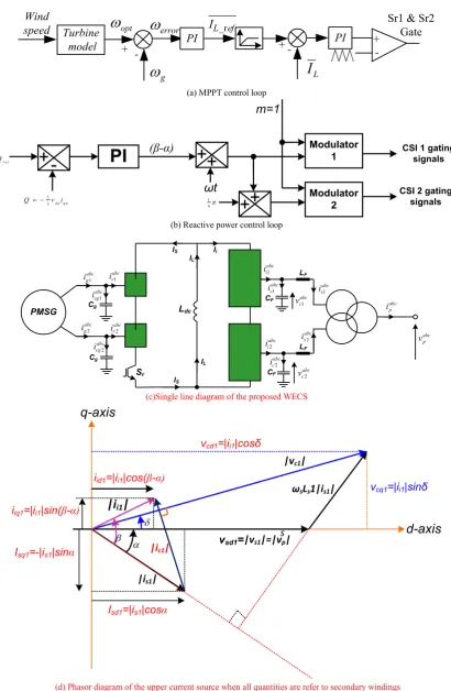
MPPT and grid reactive power controller
Fig. 2(a) shows the MPPT control loop which is incorporated within wind turbine and drive train model,
including the gear box ratio, and it calculates the corresponding optimal generator speed ωopt. A proportional
integral (PI) controller is used to calculate the reference average inductor current (𝐼̅̅̅̅̅̅̅ 𝐿_𝑟𝑒𝑓), from the speed
controller that forces the generator actual speed to follow the optimal speed set by the MPPT controller; see Fig.
2(a). The inner loop is the current controller that regulates average inductor current (𝐼̅𝐿) and generates the duty
cycle for switches Sr1 and Sr2.
The reactive power controller in Fig. 2(b) adjusts the phase angle α between the grid voltage and current dual
CSI output current. Thus, α is added to angle ωt, which is estimated from the phase locked loop (PLL), and the
resultant angle ωt+α is used as the time base for CSI1, and CSI2, however, the time based for CSI2 is modified
to ωt+α+𝜋6 to compensate for the phase shift introduced by the transformer winding, see Fig. 2(b).
To establish the relationship between the grid delivered active/reactive power and the dc-link inductance
average current 𝐼̅𝐿 and the phase angle α. Assuming the line-to-line voltage of all windings are equal: vp=vs1=vs2,
and the turn ratios of the transformer secondary and tertiary windings relative to primary are N1/N2=1 and
N1/N3=1/√3 respectively. Based on single line diagram shown in Fig. 2(c) the relation between the transformer
primary and seconders currents are given in (16).
1 2
abc abc abc
p s s
i i i (16)
The relation between the two transformer secondary current (is1 and is2) and dual CSI output current (ii1 and ii2)
and dual CSI filter capacitor current (ici1 and ici2) are as following:
1 1 1
abc abc abc
s i c
i i i (17)
2 2 2
abc abc abc
s i c
i i i (18)
With transformer primary leakage impedance is being referred to star connected secondary winding and delta connected tertiary winding (
L
s1
L
s
L
F
L
sp andL
s2
L
tL
F
L
tp), the dual CSI C-filter voltages (1
abc c
v
andv
cabc2 ), and currents (i
cabc1 andi
cabc2 ) are expressed as:1
1 1 1
abc
abc s abc
c s di s
v L v
dt
1 1
abc
abc c
c Fdv
i C
dt
(20)
2
2 2 2
abc
abc s abc
c s di s
v L v
dt
(21)
2 2
abc
abc c
c Fdv
i C
dt
(22)
The steady state representation of the first set of dual CSI C-filter and current in the dq frame are:
1 1 1 1
cd sd s s sq
v v L i (23)
1 1 1 1
cq sq s s sd
v v L i (24)
1 1
cd s F cq
i C v (25)
1 1
cq s F cd
i C v (26)
Substituting equations (23) in (25) and (24) in (26) the dual CSI C-filter current can be expressed as following:
1 1 1 1
cd s F sq s s sd
i C v L i (27)
1 1 1 1
cq s F sd s s sq
i C v L i (28)
Substituting equations (27) and (28) in (17) to get the transformer seconders is1 current in dq farm can express as
following:
1
1 2
1
1
d i s F sq sd
s F s
m I C v
i
C L
(29)
1
1 2
1
1
q i s F sd sq
s F s
m I C v
i
C L
(30)
Similarly, the dq currents at transformer tertiary winding are:
2
2 2
2
1
d i s F sq sd
s F s
m I C v
i
C L
(31)
2
2 2
2
1
q i s F sd sq
s F s
m I C v
i
C L
(32)
Where Ii is the average dual CSI input current,mdmcos( ) and mqmsin( ) are d and q components
of the modulating signals. Since the modulation index ‘m’ is fixed at ‘1’ for simplicity, mdcos( ) and
cos( )
q
m . This means both active and reactive powers are being controlled using( ). Recall that the
relationship between the average dc current at the input of the dual CSI and the average dc-link inductance
current IL is:
1
i L
I I (33)
With assumption lossless interfacing transformer, the active and reactive power delivered to ac grid are:
1 1 2 2 1 1 2 2
pd pd sd sd sd sd sq sq sq sq
P v i v i v i v i v i (34)
1 1 1 1 2 2 2 2
pd pq sq sd sd sq sq sd sd sq
Fig. 2 (d) shows a phasor diagram of the upper current source converter in Fig. 2(c), and defines all direct and
quadrature currents and voltages when the voltage vector at the primary side (point of coupling at grid side) is
aligned with the d-axis. Fig. 2(c) and (b) and equations (29) to (35) show the relationships between the active
and reactive powers delivered to the grid, average inductance current, power factor angle ‘α’, and current and
voltage load angles β and δ respectively. In this paper, the maximum power point tracking (MPPT) controller
depicted in Fig. 2(a) regulates the active power to be delivered to the grid as the wind speed varies. While the
reactive power controller depicted in Fig. 2(b) is used to estimate the angle (β-α).
Furthermore, the effect of varying the average dc-link inductance current I̅L and generator current ig is
established, considering fundamental currents and voltages at the generator side. The rectifier input current is
obtained as:
1 1 1
rd gd g gq
i i eC v (36)
1 1 1
rq gq e g gd
i i C v (37)
2 2 2
rd gd g gq
i i eC v (38)
2 2 2
rq gq e g gd
i i C v (39)
The peak line fundamental current (Irp) at rectifier input is:
2 2 2 2
1 1 2 2
rp rd rq r d r q
I i i i i (40)
The relation between the peak value of the rectifier input current and dc-link average inductance current I̅L is [25]
2 3 L
rp I
I
(41)
Substituting (41)in (40)
2 2 2 2
1 1 2 2
2 3 2 3
L r d r q r d r q
I i i i i
(42)
From equation (42), the effect of adjusting the dc-side inductor current can be summarized as follows: when the
wind turbine speed exceeds the optimal speed, the speed controller will increase the average current 𝐼̅,𝐿 which in
turn increases the generator current to increase electromagnetic torque to slow down the turbine speed (ωg),
(a) MPPT control loop
(b) Reactive power control loop
(c)Single line diagram of the proposed WECS
[image:11.595.91.502.66.695.2](d) Phasor diagram of the upper current source when all quantities are refer to secondary windings
Fig. 2 Proposed WECS control loops and WECS single line diagram representation Wind
speed
PI +
-opt
error+ _r
L ef
I
- PI +
-Turbine model L
I
g
Sr1 & Sr2 Gate
3
2 d p q p
Q v i
r e f
Q
+-
PI
++
(β-α)
ωt
Modulator 1 Modulator 2 16
++
m=1
CSI 1 gating signals
CSI 2 gating signals LF LF CF CF 2 abc s i 1 abc s i 1 abc c i 2 abc c i 2 abc c v 1 abc c v 1 abc i i 2 abc i i abc p i abc p v PMSG 1 abc g i 2 abc g i 1 abc r i 2 abc r i 2 abc cg i 1 abc cg i Cg Cg IS IL IL IS Ii
Ldc
Sr
|is1|
|i
i1|
|vs1|=|vsp|
|vc1|
ωsLs1|is1|
Isd1=|is1|cosα
Isq1=-|is1|sinα |ic1|
iiq1=|ii1|sin(β-α)
iid1=|ii1|cos(β-α)
vsd1=
vcd1=|ii1|cosδ
vcq1=|ii1|sinδ
IV.
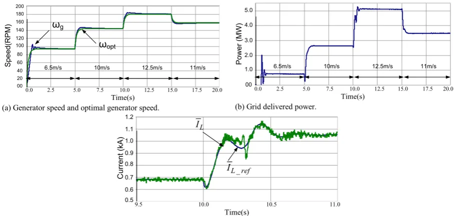
Simulation Results
a. Healthy operation
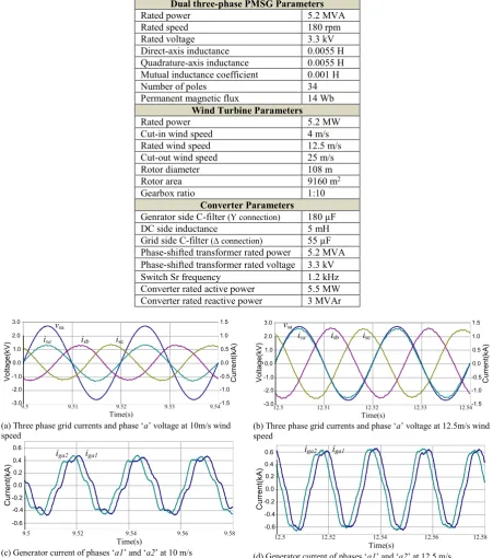
The WECS in Fig. 1(b) is simulated using PSCAD/EMTDC. The simulation system parameters are shown in
Table 1. To assess the steady state and dynamic performance of the proposed WECS, the system is simulated at
several wind speeds, starting from 6.5m/s to rated wind speed, 12.5m/s. Fig. 3 shows waveforms that illustrate
the overall performance of the proposed WECS. Fig. 3 (a) shows that the proposed WECS tracks the optimal
speed with minimum transients as the wind speed varies. Fig. 3(b) displays the changes in active power
delivered into the grid by the dual CSI, as wind speed varies. Fig. 3(c) shows that the average dc-link inductor
current increases with power delivered to the grid when the wind speed is increased from 10m/s to 12.5m/s, with
the current controller able to track (𝐼̅̅̅̅̅̅̅𝐿_𝑟𝑒𝑓) with minimum transient. Fig. 4(a) and (b) show grid currents and
phase ‘a’ voltage at 10m/s and 12.5m/s wind speeds, and observe that the proposal BTB converter delivers to
the grid, sinusoidal current at near unity power factor. Fig. 4 (c) and (d) show the generator current of phases
‘a1’ and ‘a2’ at 10m/s and12.5m/s, which have different magnitude and frequency, as expected. Fig. 5 shows
waveforms that analyse the converter performance. Fig. 5(a) shows the dc-link current, switch Sr1current and
CSI1 input current Ii1, and observe that when the switch Sr1 is on, the dc-link inductance current builds up
(charging mode), and when the switch Sr1 is off, the dc-link inductance current decreases and equals to the CSI1
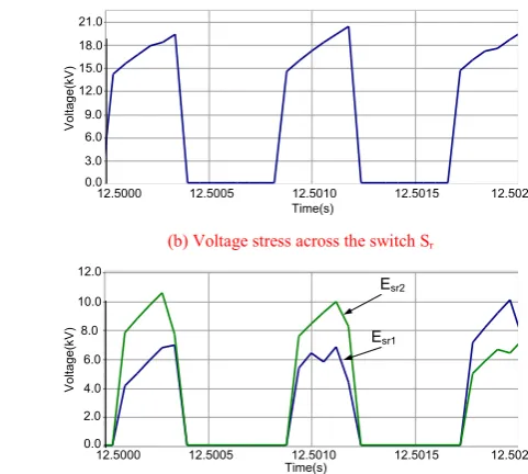
input current Ii1 (discharging mode). Fig. 5(b) and (c) show voltage stresses in the switches of the proposed
WECS shown in Fig. 1(a) and of the modified version shown in Fig. 1(b) respectively/ Observe that the voltage
stress in the switches of the modified version in Fig. 1(b) is half of the WECS in Fig. 1(a).
(a) Generator speed and optimal generator speed. (b) Grid delivered power.
(c) Average dc-link inductor current during transient from Case 3 to Case 4. Fig. 3 PSCAD/EMTD simulation waveforms of the second WECS proposed.
Main : Graphs
0.0 2.5 5.0 7.5 10.0 12.5 15.0 17.5 20.0 ... ... ... 0
20 40 60 80 100 120 140 160 180 200
y
genrator speed optimal speed
Time(s)
0.0 2.5 5.0 7.5 10.0 12.5 15.0 17.5 20.0
00 80 60 40 20 160 140 120 100 180 200
S
pe
ed
(R
P
M
) ωg
ωopt
6.5m/s 10m/s 12.5m/s 11m/s
Main : Graphs
0.0 2.5 5.0 7.5 10.0 12.5 15.0 17.5 20.0 ... ... ... 0.0
1.0 2.0 3.0 4.0 5.0
y
grid pow er
Time(s)
0.0 2.5 5.0 7.5 10.0 12.5 15.0 17.5 20.0
00 3.0
1.0 4.0 5.0
P
ow
er
(
M
W
)
6.5m/s 10m/s 12.5m/s 11m/s 2.0
Main : Graphs
9.50 10.00 10.50 11.00 ...
... ... 0.50
0.60 0.70 0.80 0.90 1.00 1.10 1.20
y
ref coil current coil current
Time(s)
9.5 10.0 10.5 11.0 0.5
0.8
0.7
0.6 1.0
0.9 1.1 1.2
C
ur
re
nt
(
kA
)
L
I
_ L ref
[image:12.595.70.524.531.747.2]Table 1 The WECS PSCAD/EMTDC setup parameters Dual three-phase PMSG Parameters
Rated power 5.2 MVA
Rated speed 180 rpm
Rated voltage 3.3 kV
Direct-axis inductance 0.0055 H
Quadrature-axis inductance 0.0055 H
Mutual inductance coefficient 0.001 H
Number of poles 34
Permanent magnetic flux 14 Wb
Wind Turbine Parameters
Rated power 5.2 MW
Cut-in wind speed 4 m/s
Rated wind speed 12.5 m/s
Cut-out wind speed 25 m/s
Rotor diameter 108 m
Rotor area 9160 m2
Gearbox ratio 1:10
Converter Parameters
Genrator side C-filter (Y connection) 180 µF
DC side inductance 5 mH
Grid side C-filter (∆ connection) 55 µF
Phase-shifted transformer rated power 5.2 MVA
Phase-shifted transformer rated voltage 3.3 kV
Switch Sr frequency 1.2 kHz
Converter rated active power 5.5 MW
Converter rated reactive power 3 MVAr
(a) Three phase grid currents and phase ‘a’ voltage at 10m/s wind
speed (b) Three phase grid currents and phase ‘speed a’ voltage at 12.5m/s wind
(c) Generator current of phases ‘a1’ and ‘a2’ at 10 m/s (d) Generator current of phases ‘a1’ and ‘a2’ at 12.5 m/s
Fig. 4 Simulation waveforms of the grid phase ‘a’ voltage and three-phase grid current at 10m/s and 12.5m/s wind speeds, and generator currents at 10m/s and 12.5m/s wind speeds.
Main : Graphs
9.500 9.510 9.520 9.530 9.540 ...
... ... -3.0 -2.0 -1.0 0.0 1.0 2.0 3.0 y
grid voltage grid current
Time(s)
9.5 9.51 9.52 9.53 9.54
-2.0 -3.0 0.0 -1.0 1.0 V ol ta ge (k V
) 2.0
3.0 -1.0 -1.5 0.0 -0.5 0.5 1.0 1.5 C ur re nt (k A ) vsa
isa isb isc
Main : Graphs
12.500 12.510 12.520 12.530 12.540 ...
... ... -3.0 -2.0 -1.0 0.0 1.0 2.0 3.0 y
grid voltage grid current
Time(s)
12.5 12.51 12.52 12.53 12.54
-2.0 -3.0 0.0 -1.0 1.0 V ol ta ge (k V
) 2.0
3.0 -1.0 -1.5 0.0 -0.5 0.5 1.0 1.5 C ur re nt (k A ) vsa
isa isb isc
Untitled_5 : Graphs
9.500 9.520 9.540 9.560 9.580 ...
... ... -3.0 -2.0 -1.0 0.0 1.0 2.0 3.0 y genrator current Time(s)
9.5 9.52 9.54 9.56 9.58
-0.6 0.0 -0.4 0.2 C ur re nt (k A
) 0.4
0.6
-0.2
iga1 iga2
Main : Graphs
12.500 12.510 12.520 12.530 12.540 ...
... ... -3.0 -2.0 -1.0 0.0 1.0 2.0 3.0 y
grid voltage grid current
Time(s)
12.5 12.52 12.54 12.56 12.58
-0.6 0.0 -0.4 0.2 C ur re nt (k A
) 0.4
0.6 vsa
isa isb isc
Untitled_5 : Graphs
12.500 12.520 12.540 12.560 12.580 ...
(a) Currents in the dc-link inductance IL, switch Sr1 and at the input
of the CSI1 Ii1.
(b) Voltage stress across the switch Sr
(c) Voltage stresses on the Switches Sr1 and Sr2 of the modified
[image:14.595.276.517.68.284.2]version of the WECS
Fig. 5 waveforms show the performance of the proposed convertesr.
b. Low voltage ride-through (LVRT)
This subsection investigates the fault ride-through capability of the proposed WECS. During LVRT, the dual
CSI cannot deliver the active power produced by the wind turbine to the grid. This will create a significant
power imbalance between the dual CSI ac and dc sides; thus, causes 𝐼̅̅̅̅̅̅̅𝐿_𝑟𝑒𝑓 to increase to compensate the drop in
the grid voltage. The current limiter implemented within the proposed control limits the reference current to
1.2kA, to protect the power electronics devices from over current, see Fig. 2(a). During the LVRT, the wind
turbine speed builds up, and the extra kinetic energy is stored in the large inertia of the wind turbine. Under
extended period of voltage dip, the generator speed will keep increasing, and this will expose converter switches
to overvoltage. To overcome this issue, a dc active crowbar (braking chopper Scb1,Scb2 and Rcb1,Rcb2 in Fig. 1(b))
is added to limit the wind turbine speed increase until the pitch angle controller takes action (progressively over
10 to 20s). The dc active crowbar is activated when the generator speed is more than 10% of rated speed. During
simulation the wind speed was set to 12.5m/s, and at t=5s, the grid voltage drops to 10% of its rated value for
140ms, and then recovers. This simulation scenario is selected to show the performance of the proposed WECS
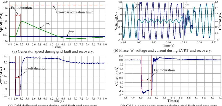
under LVRT. Fig. 6 shows waveforms that summarize the WECS overall performance. Fig. 6 (a) shows the
generator speed, where during LVRT the generator speed increases but insufficient to activate the crowbar. Fig.
6(b) shows the grid phase ‘a’ voltage and current; where the proposed WECS delivers reactive current to the
grid during LVRT. Fig. 6 (c) shows that the grid delivered power reduces to zero during LVRT and smoothly
recovers when the fault is cleared. The energy stored during the grid fault is transferred to the grid when the
IL1 current
Sr1 current
Ii1 current
Sr1→ON Sr1→OFF
12.5000 12.5005 12.5010 12.5015 12.5020
Time(s) 0.0 0.3 0.6 0.9 1.2 0.0 0.3 0.6 0.9 1.2 0.9 1.0 1.1 1.2 1.3 C ur re nt (k A ) C ur re nt (k A ) C ur re nt (k A )
12.5000 12.5005 12.5010 12.5015 12.5020 Time(s) 0.0 V ol ta ge (k V )
Untitled_2 : Graphs
8.0000 8.0005 8.0010 8.0015 8.0020 ...
... ... 0.0 3.0 6.0 9.0 12.0 15.0 18.0 21.0 y <Untitled> 3.0 6.0 9.0 12.0 15.0 18.0 21.0
12.5000 12.5005 12.5010 12.5015 12.5020 Time(s) 0.0 V ol ta ge (k V )
Untitled_2 : Graphs
8.0000 8.0005 8.0010 8.0015 8.0020 ...
... ... 0.0 3.0 6.0 9.0 12.0 15.0 18.0 21.0 y <Untitled> 2.0 4.0 6.0 8.0 10.0 12.0
Untitled_2 : Graphs
8.0000 8.0005 8.0010 8.0015 8.0020 ...
fault is cleared. Fig. 6 (d) show that the q-component of the grid current increases to the rated value during
LVRT, and decreases to zero after the grid fault.
(a) Generator speed during grid fault and recovery. (b) Phase ‘a’ voltage and current during LVRT and recovery.
(c) Grid delivered power during grid fault and recovery. (d) Grid q-component current during grid fault and recovery Fig. 6 Waveforms summarise the overall performance of the proposed WECS during a LVRT condition.
V.
Experimental Results
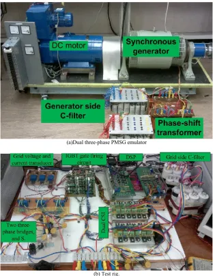
The performance of the proposed WECS shown in Fig. 1(a) is experimentally evaluated, with different cases
used to assess its dynamic performance Fig. 7(a) Shows the dual three-phase PMSG emulator, which consists of a
three-phase synchronous generator connected to a phase-shift transformer. Fig. 7(b) shows the 2kVA
experimental test rig. The experimental parameters are given in Table 2.The experimental test is at three
different wind speeds; each lasting for 40s, with initial wind speeds at 6m/s, which undergoes a step increase to
8m/s and then to 7m/s. This sequence is repeated to enable examination of the dynamic performance and stability
of the proposed system. The corresponding optimal generator speeds at each wind speed are 600 rpm, 800 rpm
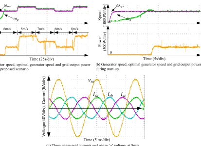
and 700 rpm respectively. Fig. 8 and Fig. 9 show experimental waveforms from the WECS. Fig. 8(a) shows the
generator is able to track the optimal speed and produces the corresponding active power being delivered to the
grid at the different wind speeds. The proposal speed controller forces the generator to run at the optimal speed
with minimal transient and oscillations at different wind speed conditions. Also Fig. 8 (a) shows the active
power delivered to the grid changes smoothly with minimum oscillation. Fig. 8(b) shows that the proposed
speed control loop ensures soft started up. Fig. 8 (c) shows a snapshot of the output current injected into grid
and phase ‘a’ voltage at 8m/s wind speed, where the grid current is sinusoidal, with nearly zero reactive power.
Fig. 9 (a) shows a detailed view of the dc-link inductor current IL, dual CSI input current Ii and switch current Is.
From Fig. 9(a), when the switch Sr is on, the dc-link inductor current rises and equals the switch current Is, and
Main : Graphs
4.80 5.20 5.60 6.00 6.40 6.80 7.20 7.60 8.00 ... ... ... 176.0 180.0 184.0 188.0 192.0 196.0 200.0 y
optimal speed genrator speed
4.8 5.0 5.2 5.4 5.6 5.8 6.0 6.2 6.4 6.6 6.8 7.0 7.2 7.4 7.6 7.8 8.0 Time(s) 176 180 184 188 192 196 200 S pe ed (R P M ) ωopt ωg Fault duration
Crowbar activation limit
Main : Graphs
4.950 5.000 5.050 5.100 5.150 5.200 5.250 ... ... ... -3.0 -2.0 -1.0 0.0 1.0 2.0 3.0 y
grid current grid voltage
4.95 5.00 5.05 5.10 5.15 5.20 5.25
Time(s) -3.0 -2.0 -1.0 0.0 1.0 2.0 3.0 V ol ta ge (k V ) -1.5 -1.0 -0.5 0.0 0.5 1.0 1.5 C ur re nt ( kA )
vsa isa
Main : Graphs
4.80 5.20 5.60 6.00 6.40 6.80 7.20 7.60 8.00 ... ... ... 0.0 1.0 2.0 3.0 4.0 5.0 6.0 y
grid pow er
4.8 5.0 5.2 5.4 5.6 5.8 6.0 6.2 6.4 6.6 6.8 7.0 7.2 7.4 7.6 7.8 8.0
Time(s) 0.0 1.0 2.0 3.0 4.0 5.0 6.0 P ow er (M W
) Fault duration
Main : Graphs
4.80 4.90 5.00 5.10 5.20 5.30 5.40 5.50 5.60 5.70 5.80 5.90 6.00 ... ... ... -1.60 -1.40 -1.20 -1.00 -0.80 -0.60 -0.40 -0.20 0.00 0.20 y Igrid_Q
4.8 4.9 5.0 5.1 5.2 5.3 5.4 5.5 5.6 5.7 5.8 5.9 6.0
[image:15.595.76.520.119.332.2]the dual CSI input current Ii equals zero, while when the switch is off the dc-link inductor current IL falls to the
dual CSI input current Ii, and the switch current Is is zero. Fig. 9(b) show the dual CSI output currents ‘ia1’ and
‘ia2’, where the dual CSI converters the input current Ii to ac current.
(a)Dual three-phase PMSG emulator
[image:16.595.141.457.143.548.2](a) Generator speed, optimal generator speed and grid output power during the proposed scenario.
(b) Generator speed, optimal generator speed and grid output power during start-up.
[image:17.595.106.520.70.371.2](c) Three phase grid currents and phase ‘a’ voltage, at 8m/s. Fig. 8 Waveforms showing the overall performance of the proposed WECS.
(a) dc-side inductor current IL, switch current IS, and CSI input
current Ii at 8m/s wind speed.
(b) Dual CSI phase output current ‘ii1_a’ and ‘ii2_a’at 8m/s.
[image:17.595.128.509.403.536.2]Fig. 9 Waveforms analyse the dc-side inductance current, switch current, CSI input current, and dual CSI output current Table 2 Experimental parameters
Wind Turbine Parameters Power at rated wind speed 4.6 kW Cut-in wind speed 4 m/s Rated wind speed 12.5m/s
Rotor diameter 3.2 m
Rotor area 8.04 m2
Gearbox ratio 1:2.07
DC motor Parameters Rated armature voltgae 460 V
Rated speed 1500 rpm
Rated current 16 A
Field current 1.2 A
Armature resistance 2.5 Ω
Toque constant Km 2.47
Synchronus machine parmeters
Rated speed 1500 rpm
Rated voltgae 400 V
ωg ωopt
0
0
S
pe
ed
(1
00
R
P
M
/d
iv
)
P
ow
er
(5
00
W
/d
iv
)
Time (25s/div)
6m/s 8m/s 7m/s 6m/s 8m/s
ωg ωopt
0
0
S
pe
ed
(1
00
R
P
M
/d
iv
)
P
ow
er
(5
00
W
/d
iv
)
Time (5s/div)
v
sai
sai
sbi
scV
ol
ta
ge
(4
0V
/d
iv
),
C
ur
re
nt
(5
A
/d
iv
)
Time (5 ms/div)
Ii
Is
IL
Time(250 µs/div)
C
ur
re
nt
(1
0A
/d
iv
)
i
i1_ai
i2_aTime (2.5 ms/div)
C
ur
re
nt
(1
0A
/d
iv
[image:17.595.190.407.590.762.2]Rated current 10 A
Rated frequency 50 Hz
Number of poles 4
Field current 0.5 A
Genrator voltgae constant KG 2.5
armature restance 1.2 Ω armature inductance 36 mH
Genrator side phase shift transformer parmeters
Rated power 2 kVA
Primary rated voltge 415V (∆ connection) Two secondary winding rated voltage 400V (Y connection) 415V (∆ connection)
Converter parameters
Genrator side Cfilter 120 µF (Y connection) dc-link inductance 5 mH
Grid side C-filter 55 µF (∆ connection) grid side phase shift transformer parmeters
Rated power 2 kVA
Primary winding rated voltge 415 V (Y connection) Two secondary winding rated voltage 208 V (Y connection) 208 V (∆ connection)
VI.
CONCLUSIONS
This paper proposed new dual three-phase BTB CSC and explored its application in multi-megawatt WECS.
The use of diode rectifiers with a phase-shift transformer or multi-phase machine as suggested in this paper at
the input side, eliminates pulsating torque due to 5th and 7th harmonics. Besides power circuit and control
systems simplicity, the proposed BTB converter offers zero switching losses in the grid side converter.
Additionally, this paper investigated the possibility of extending the proposal WECS in order to effectively
reduce the voltage stress on the switch Sr, by using dual converters. Simulation and experimental results show
that proposed WECS can satisfy ride-through requirements and has good dynamic performance, with stable ac
grid output voltage and current waveforms over a wide wind speed range.
VII.
References
[1] N. Gyawali, Y. Ohsawa, and O. Yamamoto, "Power management of double-fed induction
generator-based wind power system with integrated smart energy storage having superconducting magnetic
energy storage/fuel-cell/electrolyser," Renewable Power Generation, IET, vol. 5, pp. 407-421, 2011.
[2] H. Li and Z. Chen, "Overview of different wind generator systems and their comparisons," Renewable
Power Generation, IET, vol. 2, pp. 123-138, 2008.
[3] E. Lepa, T. Thurnherr, and A. Faulstich, "Design and testing of a 7 MW wind turbine medium voltage
electrical drivetrain with medium speed permanent magnet synchronous generator," EWEA 2013
Europe's Premier Wind Energy Event, pp. 1-8, 2013.
[4] O. Alizadeh and A. Yazdani, "A Strategy for Real Power Control in a Direct-Drive PMSG-Based Wind
Energy Conversion System," Power Delivery, IEEE Transactions on, vol. 28, pp. 1297-1305, 2013.
[5] J. M. Espi and J. Castello, "Wind Turbine Generation System With Optimized DC-Link Design and
Control," Industrial Electronics, IEEE Transactions on, vol. 60, pp. 919-929, 2013.
[6] A. Uehara, A. Pratap, T. Goya, T. Senjyu, A. Yona, N. Urasaki, and T. Funabashi, "A Coordinated
Control Method to Smooth Wind Power Fluctuations of a PMSG-Based WECS," Energy Conversion,
IEEE Transactions on, vol. 26, pp. 550-558, 2011.
[7] G. O. Suvire and P. E. Mercado, "Combined control of a distribution static synchronous
compensator/flywheel energy storage system for wind energy applications," Generation, Transmission
[8] X. Yuanye, K. H. Ahmed, and B. W. Williams, "Wind Turbine Power Coefficient Analysis of a New
Maximum Power Point Tracking Technique," Industrial Electronics, IEEE Transactions on, vol. 60,
pp. 1122-1132, 2013.
[9] M. Singh, V. Khadkikar, and A. Chandra, "Grid synchronisation with harmonics and reactive power
compensation capability of a permanent magnet synchronous generator-based variable speed wind
energy conversion system," Power Electronics, IET, vol. 4, pp. 122-130, 2011.
[10] Z. Shao, T. King-Jet, D. M. Vilathgamuwa, N. Trong Duy, and W. Xiao-Yu, "Design of a Robust Grid
Interface System for PMSG-Based Wind Turbine Generators," Industrial Electronics, IEEE
Transactions on, vol. 58, pp. 316-328, 2011.
[11] L. Jun, S. Bhattacharya, and A. Q. Huang, "A New Nine-Level Active NPC (ANPC) Converter for
Grid Connection of Large Wind Turbines for Distributed Generation," Power Electronics, IEEE
Transactions on, vol. 26, pp. 961-972, 2011.
[12] N. P. W. Strachan and D. Jovcic, "Stability of a Variable-Speed Permanent Magnet Wind Generator
With Weak AC Grids," Power Delivery, IEEE Transactions on, vol. 25, pp. 2779-2788, 2010.
[13] E. Levi, "Multiphase Electric Machines for Variable-Speed Applications," Industrial Electronics, IEEE
Transactions on, vol. 55, pp. 1893-1909, 2008.
[14] L. Parsa, "On advantages of multi-phase machines," in Industrial Electronics Society, 2005. IECON
2005. 31st Annual Conference of IEEE, 2005, p. 6 pp.
[15] A. A. Nahome, R. Zaimeddine, L. Bing, and T. Undeland, "Vector control of direct drive six phase
permanent magnet synchronous generators," in PowerTech, 2011 IEEE Trondheim, 2011, pp. 1-7.
[16] S. Kato, Y. Inui, M. Michihira, and A. Tsuyoshi, "Low-Cost Wind Generator System with a Permanent
Magnet Synchronous Generator and Diode Rectifiers," in ICREPQ’06 International Conference on
Renewable Energy and Power Quality, 2006.
[17] H. Weihao, W. Yue, S. Xianwen, and W. Zhaoan, "A Novel Sensorless Unity Power Factor Control
Method for Six-phase PMSG in Direct Drive Wind Energy Conversion Systems," in Applied Power
Electronics Conference and Exposition, 2009. APEC 2009. Twenty-Fourth Annual IEEE, 2009, pp. 744-749.
[18] M. J. Duran, S. Kouro, W. Bin, E. Levi, F. Barrero, and S. Alepuz, "Six-phase PMSG wind energy
conversion system based on medium-voltage multilevel converter," in Power Electronics and
Applications (EPE 2011), Proceedings of the 2011-14th European Conference on, 2011, pp. 1-10.
[19] L. Jiawen, N. Heng, and S. Yipeng, "Dual stator windings PMSG fed by half-controlled converters for
wind power application," in Electrical Machines and Systems (ICEMS), 2011 International Conference
on, 2011, pp. 1-6.
[20] I. Abdelsalam, G. P. Adam, D. Holliday, and B. W. Williams, "Assessment of a wind energy
conversion system based on a six-phase permanent magnet synchronous generator with a twelve-pulse
PWM current source converter," in ECCE Asia Downunder (ECCE Asia), IEEE, 2013, pp. 849-854.
[21] I. Abdelsalam, G. P. Adam, D. Holliday, and B. W. Williams, "New back-to-back current source
converter with soft start-up and shutdown capabilities," in Power Electronics, Machines and Drives
(PEMD 2014), 7th IET International Conference on, 2014, pp. 1-5.
[22] I. Abdelsalam, G. P. Adam, D. Holliday, and B. W. Williams, "Modified back-to-back current source
converter and its application to wind energy conversion systems," IET Power Electronics, vol. 8, pp.
103-111, 2014.
[23] I. Abdelsalam, G. P. Adam, D. Holliday, and B. W. Williams, "Single-stage ac–dc buck–boost
converter for medium-voltage high-power applications," Renewable Power Generation, IET, vol. 10,
pp. 184-193, 2016.
[24] D. O'Kelley and S. Simmons, Introduction to generalized electrical machine theory: McGraw-Hill,
1968.
[25] I. Abdelsalam, G. P. Adam, D. Holliday, and B. W. Williams, "Three-phase ac–dc buck–boost
converter with a reduced number of switches," Renewable Power Generation, IET, vol. 9, pp. 494-502,
2015.
[26] D. G. Holmes and T. A. Lipo, Pulse Width Modulation for Power Converters: Principles and Practice: